The system module utilizes the following components:
- ESP32 board
- MAX6675 thermocouple module
- Four 5V LEDs is connected with the ESP32. The number of LEDs may vary depending on the number of CAISSE module.
ESP32 board pinout diagram:

MAX6675 thermocouple module pinout:

The MAX6675 thermocouple is connecteded to the ESP32 as follorwing:
- S0 pin to GPIO27
- CS pin to GPIO14
- SCK pin to GPIO12
The four LEDs indicating CAISSE module with be connected with GPIO 19, 18 ,5, 17 of the ESP32

The caisse module utilizes the following components:
- ESP32 board
- SW-420 vibration-sensor-module
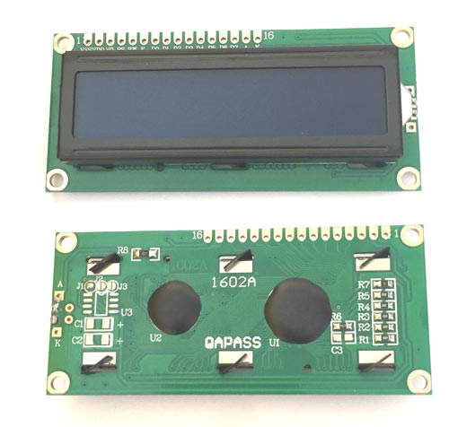
- 2x16 LCD I2C display
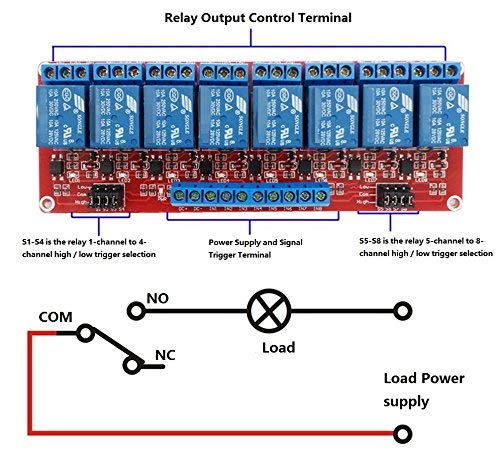
- 8 channel 5V relay module
- A custom made PCB board (See GERBERS file)
SW-420 vibration sensor module pinout diagram:

2x16 LCD I2C display module pinout:

8 channel 5V relay module pinout:

The SW-420 vibration-sensor-module is connecteded to the ESP32 as follorwing:
- D0 pin to GPIO13
The 2x16 LCD I2C display module is connecteded to the ESP32 as follorwing:
- SCL pin to GPIO22
- SDA pin to GPIO21
The 8 channel 5V relay module is connecteded to the ESP32 as follorwing:
- Relay 1 input pin to GPIO19
- Relay 2 input pin to GPIO18
- Relay 3 input pin to GPIO5
- Relay 4 input pin to GPIO17
- Relay 5 input pin to GPIO16
- Relay 6 input pin to GPIO4
- Relay 7 input pin to GPIO0
- Relay 8 input pin to GPIO15


You can find the caisse-module-gerber files here
Download and install the arduino ide by following this link ARDUINO IDE
Install ESP32 board add-on in Arduino IDE by following this link ESP32 ADD-ON
The WiFiManager library for ESP32 provides an easy way to configure and manage WiFi connections in your projects. It offers features such as:
- Captive portal for setting WiFi credentials
- Ability to store WiFi credentials in Non-Volatile Memory (NVM)
- Option to automatically connect to a previously saved network
- Option to have multiple access points with custom settings
- Support for custom parameters in the configuration portal To use the library, you can follow this tutorial to setup and use the wifi-manager library. Then, you can initialize the WiFiManager object and use its functions to set up and control the WiFi connection.
Install following this link HTTPClient
Install MAX6675 library from the arduino library manager
Install telegram bot library in Arduino IDE by following this link UniversalTelegramBot
Input your: ssid, password, channel, hide_SSID=true/false, max_connection
WiFi.softAP("SYSTEM_CAISSE", "123456789", CHANNEL, false, NUMSLAVES);
String GOOGLE_SCRIPT_ID = "input your google-script-id here" ;
String BOTtoken = "input your telegram bot-token here";
Finally you can compile and upload the system-module code to your system module
Install LiquidCrystal_I2C library from the arduino library manager
Finally you can compile and upload the caisse-module code to your system module
- Turn on module SYSTEM by powering it to 5V DC.
- Warning: Providing more than 5V will damage the module
- Use your mobile device in order to connect to the ESP32 WiFi. Select SYSTEM_LAVAGE and connect using the password (123456789 by default).
- Wait for a windows to pop up. It will display the available networks found by the module. Click to the router you wish the module needs to connect to internet. Enter the password and click SAVE.
- Wait until the page disappear. If you go back to your WiFi settings you should now see an available SSID called SYSTEM_CAISSE which confirm the module is properly set (DO NOT CONNECT TO THIS NEW NETWORK).
- Once the SYSTEM is connected, you can initiate the module CAISSE.
- As there can be multiple CAISSE, use the micro switch in order to address the module from 1 to 7 using the binary switches (we only used p to 4 CAISSEs here).
- Then power it up and wait for the LED to turn on. If the module did not manage to connect to SYSTEM, the LED will blink 3 time before it restarts.
- An isolate mode is available if all switches are put to zero. The module CAISSE will start without connecting to the SYSTEM and can be used for test purpose.
- Once the module is connected and you can see the message BONJOUR on the LCD screen, turn OFF the module SYSTEM and ON again. Wait until the LED linked to the CAISSE id turns ON. This means both modules are ready to communicate as their mac addresses have been saved to both memories.
- Perform the same process as 2 for all other module CAISSE.