Zigbee FAQ Waking BRD4180A BRD4181A with Buttons
Table of Contents
On series 2, only the pins of GPIO port A and B remain full fuctional in sleep mode. In other words, only pins from GPIO port A and B are capable of waking the chip from sleep mode. Besides that, the GPIO_EM4WUx pins are also capable of waking the chip from sleep mode, but they need extra settings.
Unfortunately, on our radio board BRD4180A/BRD4181A, PD2 and PD3 is used as the buttons, so we can't use the two buttons of BRD4180A/BRD4181A to wake up the device.
In this page, we will introduce the changes you need to wake up BRD4180A/BRD4181A with the buttons.
Gecko SDK Suite 2.7
- BRD4181A
Connect the WSTK to PC through USB cable
Below are the steps of setting up the projects:
-
Create the sample
ZigbeeMinimal; -
Turn to
HALtab, hit the buttonOpen Hardware Configurator, then disablebutton.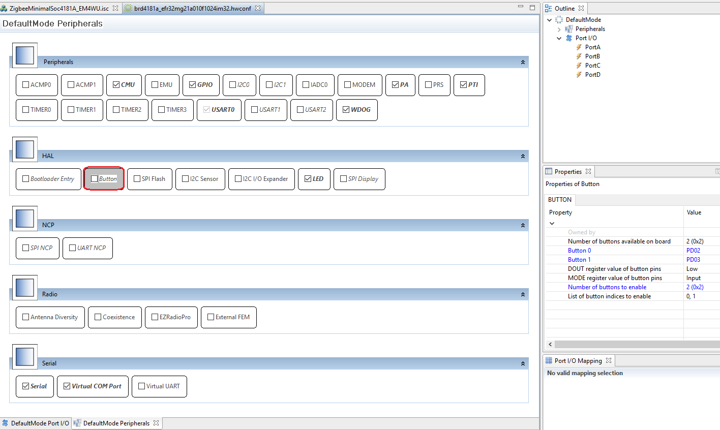
-
Turn to
Callbackstab, select the following callbacks:- emberAfMainInitCallback
-
Save and generate.
-
Edit the source file
ZigbeeMinimalSoc4181A_EM4WU_callbacks.c, add the following source code:extern bool emAfForceEndDeviceToStayAwake; void hal_EM4WU_Isr(uint8_t pin) { halToggleLed(1); emAfForceEndDeviceToStayAwake = !emAfForceEndDeviceToStayAwake; } void emberAfMainInitCallback(void) { CMU_ClockEnable(cmuClock_GPIO, true); GPIO_PinModeSet(gpioPortD, 2, gpioModeInput, 1); GPIO_EM4EnablePinWakeup(1 << 25, 0); //PD2 is EM4WU9 GPIOINT_Init(); GPIO->IEN = 1<<25; //25=9+16 EM4UIEN is in the higher 16bit GPIO->EM4WUEN = 1<<25; GPIO_IntClear(1<<25); GPIOINT_CallbackRegister(25, hal_EM4WU_Isr); }
-
Modify the source file
emdrv/gpiointerrupt.c, here we need the following changes:- Change the size of the array
gpioCallbacksfrom 16 to 32, as the interrupt of GPIO_EM4WU is in the high 16bit. - Change the bit mask in function
GPIO_ODD_IRQHandlerandGPIO_EVEN_IRQHandler, from0x0000AAAAand0x00005555to0xAAAAAAAAand0x55555555respectively.
- Change the size of the array
-
Save and build.
The GPIO_EM4WUx pins are capable of waking up the chip, but they need extra settings. We need to call API GPIO_EM4EnablePinWakeup to enable these functions. After that, enable the interrupt of GPIO_EM4WU and register a handler for that interrupt.
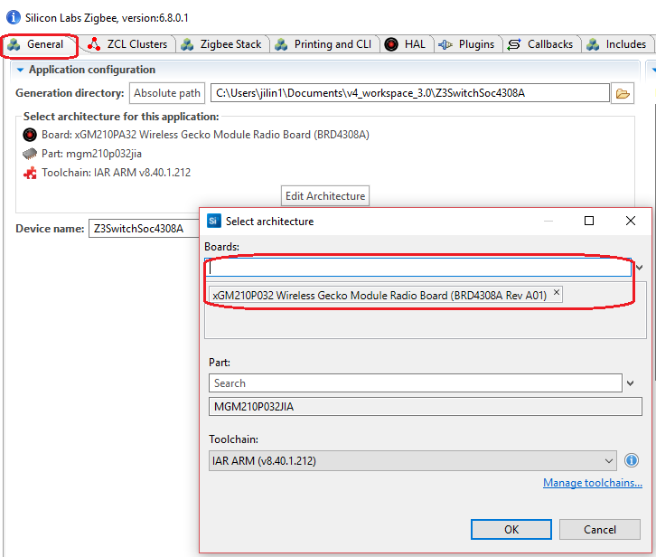
Start Simplicity Studio, import the project and then open the .isc file. Turn to "General" tab, hit the button Edit Architecture, change the board type or compiler.
NA
 Home |
 ![]() Zigbee |
Zigbee | ![]() Bluetooth |
Bluetooth | ![]() ZWave |
ZWave | ![]() Proprietary |
Proprietary | ![]() Hardware |
Hardware | ![]() Common
Common
All resources of this repository are released under license CC BY-NC-ND 4.0