This repository contains documentation and schematics for puzzles in The Locked Room, a real-life escape room built into a shipping container. Firmware for each puzzle is in the relevant directory as Arduino sketches.
The following diagram shows how each of the puzzles are wired together in the room. A PDF version of the diagram is also available. Lengths of CAT5 cable are used to link puzzles the puzzles to the main controller in a star configuration. The communication bus between the main controller and each puzzle is I2C.

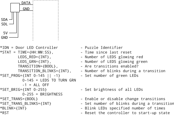
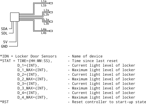
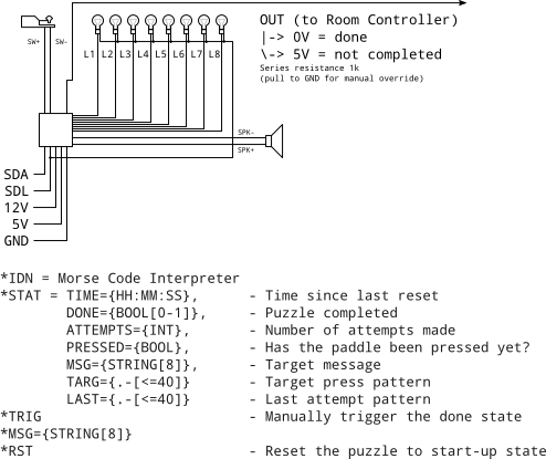
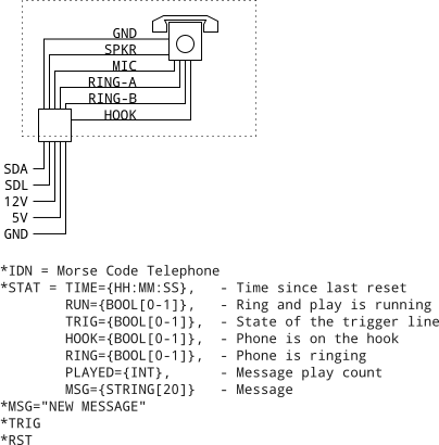
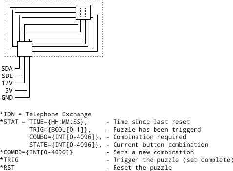
The puzzle schematics are intepreted as follows: The diagram at the top shows a simplified wiring diagram external to the module (how it connects to power and devices) The text at the bottom shows the comunication interface (message definitions). For example, sending "*IDN" over the I2C bus to the LockerSensors puzzle will result in the puzzle responding with "Locker Door Sensors". If the message "*STAT" is sent to this puzzle, it will respond with a message containing the state of the lockers.
This is the phone that is used to call the front desk to ask for clues etc. There is no electronics, the phones are just wired as shown.

This device may have been merged with another puzzle in the room.

This device controls the state of the LEDs around the door.
This device senses the state of the lockers by reading the Light Dependant Resistors placed at the rear of the lockers.
This device interprets the morse code signals generated by the tapper to check if the player has entered the correct code.
This device generates a morse code tone sequence and playes it on the phone in the room. It has the ability to ring the phone by applying the required waveform to the solenoid driven bell system.
This device reads the state of the buttons on the telephone exchange mechanism.
This device drops the puzzle boxes into the cupboard at the rear of the room. It drives two solenoids to release the boxes. The input for each is a wall switch placed within the room.
