[QUESTION] LIN_ADVANCE 1.5 -- extruder rattles *a lot*. #10272
Comments
|
Do you see any improvement with |
|
Tried that -- no difference. I've verified that with default settings pulses are ~2us wide (and pretty clean signal-wise) regardless of LIN_ADVANCE and that's way more than my steppers (TMC2224) need (100ns min step time). I've also verified that there's at least 1us delay between changing DIR and the next step. AFAICT, the timings are rather conservative for the driver. As far as I can tell, the motor does obey the frequent direction changes and that's what makes the rattling noise. I mostly wonder whether such behavior is normal for LIN_ADVANCE or not. Another things that looks suspicious to me is the high step rate with LIN_ADVANCE enabled. It looks like it tries to move filament at ~ 5mm/s with no visible acceleration/deceleration phase. Interestingly enough, jerk is set to 5 mm/s, so that may be the setting to play with. |
That's exactly what's happening. LA uses the extruder jerk value to limit the max. possible extruder speed. If this speed might be exceeded due to a high K value or high acceleration setting, the print acceleration will be reduced to stay within the given ejerk value. During each acceleration / deceleration phase, the extruder speed is offset by the calculated LA speed. In your video, it looks like the extruder is running smoothly but the noise might be missed steps. So the first thing to check would be if your extruder can actually handle an extruder jerk setting of 5 (without LA). I know this isn't straightforward, so feel free to use creative ways to do that. ;) Even if you get it to work, be prepared that you would need a quite high ejerk setting to use K values as they are on such a bowden setup without slowing down the acceleration. And even if you can do that, most reports I have so far are showing that the print results are bad anyway due to other bowden effects. Small example: When you print the calibration pattern, the line width of the fast section should recover to its nominal width after some cm. In the stated reports, the line width just stays thin until the slow section starts again. So the pressure which is built up by the extruder isn't reaching the nozzle at all. I tend to call pressure compensation not working for bowden printers and likely I will add a note regarding that in the documentation if there is no real positive feedback in the near future. |
|
@Sebastianv650 — Sounds like these would be good notes to add to the Linear Advance page "troubleshooting" section. |
|
As I mentioned, the print results in my case are actually pretty good, though I'm not sure yet whether it's due to LIN_ADVANCE or to the difference in hotend movements. On the test cube I normally see a very minor decaying wave pattern along Y axis, but it is gone when LIN_ADVANCE is on. I also see moderate improvement along the edges of X and Y letters on the cube, so I'm not ready to give up on LIN_ADVANCE yet. :-) I'll tinker a bit with jerk/acceleration/max extruder speed and see whether I can get it to be silent. |
|
Please update us soon, I'm going to try it on my machine too with a titan which only needs 2.7 mm retraction to be stringless, has a 30 cm Capricorn bowden, so it looks like it should be favorable to LA. What extruder do you have on your CR10? |
|
Tinkering with E jerk helped a little, when I cranked the jerk down to almost zero. Alas, X/Y also slowed down to a crawl, so it was not very useful. I did verify that my extruder can handle pretty high jerk, acceleration and speed at least when it does not change direction. Apparently it's the direction change that seems to mess with the driver. I may try running it exclusively in spreadcycle mode, though it does come with it's own annoying high-pitch whine.
It's stock. Hmm. Could that be that it's not the missing steps, but the filament skipping on the cogwheel? I should try cranking up the pressure and see if that helps. |
How do you test jerk without changing direction? |
|
Good point. I've only tested that it can accelerate from a standstill really fast. Practically with acceleration set at 30Kmm/s^2, the stepper gets to 5mm/s within a fraction of a ms, which is way less than a pulse period at 5mm/s. I didn't test changing direction. I guess I can do a custom command quickly switching extrusion direction. I'll try that in the evening. |
|
Nope. It's not the filament grinding. I'm out of ideas. No LIN_ADVANCE for me, I guess. :-( |
|
HUGE SUCCESS! I just got around to trying linear advance 1.5 on my heavily modded tarantula. Got around 400 mm of capricorn bowden, no geared extruder. K=0.65 looked good with the pattern generator. Just printed a test cube and it looks pretty good! I used to print everything at the same speed (infill, perimeters, external perimeters, etc) because I noticed that after printing fast inner perimeters, the start of the slow external perimeter would be overextruded because of residual pressure and leave a protuded line, which looked like banding depending on seam placement. After linear advance, this effect is almost gone. Attached a pic of a cube with 35 mm/s inner 20 mm/s outer perimeters, without and with linear advance enabled, respectively. All other settings are the same. I'm not sure what the line above the X with linear advance enabled is, but at least the problem I was solving is gone. Con is, print took 27% longer due to acceleration reduction. Current Ejerk is at 5, but I believe it can be higher, since I haven't heard a single click yet. Advice on how to calibrate Ejerk is appreciated. |

|
Great to hear it's working for you! Especialy as it shows that LA is able to work with bowden systems at least to some degree.
I would guess it has something todo with the bridging above the "X" tip, where the slicer will most likely increase the flow to some bridging flow, on the other hand the backpressure from last layer is no longer there for this short segment. One or a combination of this two effects might lead to the slight over or underextrusion you get between the tip of the X.
I don't know of a "perfect" procedure to adjust jerk, and E axis ist most likely the most difficult one. Usualy, a skipped E step should be quite visible as a stepper is allways skipping a full step so it leads to a quite hughe underextrusion.
Using your prefered K factor, increase the E jerk after a few mm on Z, like ejerk = 5 for Z=0 to 3mm, ejerk 10 for 3-6mm. Most likely on the slow-fast transition you will hear and see a skipped jerk when it happens. Turn back the jerk to a value you feel save with and do a test print. |
|
Spoke too soon probably. After prinintg that cube I printed benchy and it had two heavily undrextruded layers. Then printed it again to check if it was a random clog or something but the lines are in the same exact spot. Then printed the same gcode but with linear advance off and the lines were gone. So linear advance causing weird underextrusion? Pic attached, left if k=0, both on the right are k=0.65: |

|
@Itox001 I have similar problems. I have a Benchy here that looks to have the same extrusion problem, in the same places as yours, just less pronounced:
(lighting is deliberately positioned to accentuate the shadows between layers, making it look quite bad, but in reality it actually looks decent, best one I've ever managed to print; don't mind the dark spots left of center, that's just ink on the print, and crud on my camera lens) If you open the image in another tab and zoom to 100%, you can see similar problems around the starboard doorway, especially to the left in the image (those are the result of Slic3r not being consistent about where it places seams, besides my being unable to tune-out the pressure difference). Here's my latest attempt at the calibration pattern, after discovering and fixing a problem with my hotend (the above Benchy was printed before fixing the problem, but ultimately the fix had no appreciable effect on print quality, as it was essentially just a leak):
The lines for K=0.11 to 0.13 (cropped to highlight the transition points): The higher values (about K=0.29 to 0.39, cropped to highlight transitions) (Please excuse the "bent" look, I didn't take time to apply any lens distortion correction) As you can see, the K value that results in perfect slow->fast transitions (K=0.12), is nowhere near correct for fast->slow transitions, slow being 10 mm/s and fast being 100 mm/s, with 500 mm/s² acceleration. All of the fast->slow transitions have blobs, up to about K=0.35, but as you can see, well before that value, the ends of the fast segments begin to starve, while at the same time, the starts of the adjacent slow segments have blobs. As you can also see, the distance it takes for pressure to actually build up or bleed off just doesn't match what the math is trying to do. I think there needs to be a way to make the pressure corrections happen faster, independent of the user's normal acceleration settings (what looks good for normal purposes such as ringing may be far too slow for pressure management). @thinkyhead is this possibly related to that jerk calculation problem discussed elsewhere? The gcode that produced that test pattern```gcode ; ### Marlin K-Factor Calibration Pattern ### ; ------------------------------------------- ; ; Created: Fri Apr 06 2018 08:34:55 GMT-0400 (EDT) ; ; Settings Printer: ; Filament Diameter = 1.72 mm ; Nozzle Diameter = 0.4 mm ; Nozzle Temperature = 200 °C ; Bed Temperature = 70 °C ; Retraction Distance = 2.5 mm ; Layer Height = 0.2 mm ; Z-axis Offset = 0 mm ; ; Settings Print Bed: ; Bed Shape = Rect ; Bed Size X = 200 mm ; Bed Size Y = 200 mm ; Origin Bed Center = false ; ; Settings Speed: ; Slow Printing Speed = 600 mm/min ; Fast Printing Speed = 6000 mm/min ; Movement Speed = 7200 mm/min ; Retract Speed = 1800 mm/min ; Printing Acceleration = 500 mm/s^2 ; Jerk X-axis = firmware default ; Jerk Y-axis = firmware default ; Jerk Z-axis = firmware default ; Jerk Extruder = firmware default ; ; Settings Pattern: ; Linear Advance Version = 1.5 ; Starting Value Factor = 0 ; Ending Value Factor = 0.4 ; Factor Stepping = 0.01 ; Test Line Spacing = 4 mm ; Test Line Length Slow = 50 mm ; Test Line Length Fast = 50 mm ; Print Pattern = Standard ; Print Frame = true ; Number Lines = true ; Print Size X = 168 mm ; Print Size Y = 185 mm ; Print Rotation = 0 degree ; ; Settings Advance: ; Nozzle / Line Ratio = 1.2 ; Use BL = true ; Use FWRETRACT = true ; Extrusion Multiplier = 1 ; Prime Nozzle = true ; Prime Extrusion Multiplier = 2.5 ; Prime Speed = 1800 ; Dwell Time = 2 s ; ; prepare printing ; G28 ; home all axes M190 S70 ; set and wait for bed temp M104 S200 ; set nozzle temp and continue G29 ; execute bed automatic leveling compensation M109 S200 ; block waiting for nozzle temp G21 ; set units to millimeters M204 P500 ; set acceleration G90 ; use absolute coordinates M83 ; use relative distances for extrusion G92 E0 ; reset extruder distance G1 X100 Y100 F7200 ; move to start G1 Z0.2 F600 ; move to layer height ; ; prime nozzle ; G1 X16 Y7.5 F7200 ; move to start G1 X16 Y192.5 E19.1089 F1800 ; print line G1 X16.72 Y192.5 F7200 ; move to start G1 X16.72 Y7.5 E19.1089 F1800 ; print line G10 ; retract ; ; print anchor frame ; G1 X26 Y4.5 F7200 ; move to start G11 ; un-retract G1 X26 Y170.5 E7.5444 F600 ; print line G1 X26.48 Y170.5 F7200 ; move to start G1 X26.48 Y4.5 E7.5444 F600 ; print line G10 ; retract G1 X176 Y4.5 F7200 ; move to start G11 ; un-retract G1 X176 Y170.5 E7.5444 F600 ; print line G1 X175.52 Y170.5 F7200 ; move to start G1 X175.52 Y4.5 E7.5444 F600 ; print line G10 ; retract ; ; start the Test pattern ; G4 P2000 ; Pause (dwell) for 2 seconds G1 X26 Y7.5 F7200 ; move to start M900 K0 ; set K-factor G11 ; un-retract G1 X76 Y7.5 E2.0658 F600 ; print line G1 X126 Y7.5 E2.0658 F6000 ; print line G1 X176 Y7.5 E2.0658 F600 ; print line G10 ; retract G1 X26 Y11.5 F7200 ; move to start M900 K0.01 ; set K-factor G11 ; un-retract G1 X76 Y11.5 E2.0658 F600 ; print line G1 X126 Y11.5 E2.0658 F6000 ; print line G1 X176 Y11.5 E2.0658 F600 ; print line G10 ; retract G1 X26 Y15.5 F7200 ; move to start M900 K0.02 ; set K-factor G11 ; un-retract G1 X76 Y15.5 E2.0658 F600 ; print line G1 X126 Y15.5 E2.0658 F6000 ; print line G1 X176 Y15.5 E2.0658 F600 ; print line G10 ; retract G1 X26 Y19.5 F7200 ; move to start M900 K0.03 ; set K-factor G11 ; un-retract G1 X76 Y19.5 E2.0658 F600 ; print line G1 X126 Y19.5 E2.0658 F6000 ; print line G1 X176 Y19.5 E2.0658 F600 ; print line G10 ; retract G1 X26 Y23.5 F7200 ; move to start M900 K0.04 ; set K-factor G11 ; un-retract G1 X76 Y23.5 E2.0658 F600 ; print line G1 X126 Y23.5 E2.0658 F6000 ; print line G1 X176 Y23.5 E2.0658 F600 ; print line G10 ; retract G1 X26 Y27.5 F7200 ; move to start M900 K0.05 ; set K-factor G11 ; un-retract G1 X76 Y27.5 E2.0658 F600 ; print line G1 X126 Y27.5 E2.0658 F6000 ; print line G1 X176 Y27.5 E2.0658 F600 ; print line G10 ; retract G1 X26 Y31.5 F7200 ; move to start M900 K0.06 ; set K-factor G11 ; un-retract G1 X76 Y31.5 E2.0658 F600 ; print line G1 X126 Y31.5 E2.0658 F6000 ; print line G1 X176 Y31.5 E2.0658 F600 ; print line G10 ; retract G1 X26 Y35.5 F7200 ; move to start M900 K0.07 ; set K-factor G11 ; un-retract G1 X76 Y35.5 E2.0658 F600 ; print line G1 X126 Y35.5 E2.0658 F6000 ; print line G1 X176 Y35.5 E2.0658 F600 ; print line G10 ; retract G1 X26 Y39.5 F7200 ; move to start M900 K0.08 ; set K-factor G11 ; un-retract G1 X76 Y39.5 E2.0658 F600 ; print line G1 X126 Y39.5 E2.0658 F6000 ; print line G1 X176 Y39.5 E2.0658 F600 ; print line G10 ; retract G1 X26 Y43.5 F7200 ; move to start M900 K0.09 ; set K-factor G11 ; un-retract G1 X76 Y43.5 E2.0658 F600 ; print line G1 X126 Y43.5 E2.0658 F6000 ; print line G1 X176 Y43.5 E2.0658 F600 ; print line G10 ; retract G1 X26 Y47.5 F7200 ; move to start M900 K0.1 ; set K-factor G11 ; un-retract G1 X76 Y47.5 E2.0658 F600 ; print line G1 X126 Y47.5 E2.0658 F6000 ; print line G1 X176 Y47.5 E2.0658 F600 ; print line G10 ; retract G1 X26 Y51.5 F7200 ; move to start M900 K0.11 ; set K-factor G11 ; un-retract G1 X76 Y51.5 E2.0658 F600 ; print line G1 X126 Y51.5 E2.0658 F6000 ; print line G1 X176 Y51.5 E2.0658 F600 ; print line G10 ; retract G1 X26 Y55.5 F7200 ; move to start M900 K0.12 ; set K-factor G11 ; un-retract G1 X76 Y55.5 E2.0658 F600 ; print line G1 X126 Y55.5 E2.0658 F6000 ; print line G1 X176 Y55.5 E2.0658 F600 ; print line G10 ; retract G1 X26 Y59.5 F7200 ; move to start M900 K0.13 ; set K-factor G11 ; un-retract G1 X76 Y59.5 E2.0658 F600 ; print line G1 X126 Y59.5 E2.0658 F6000 ; print line G1 X176 Y59.5 E2.0658 F600 ; print line G10 ; retract G1 X26 Y63.5 F7200 ; move to start M900 K0.14 ; set K-factor G11 ; un-retract G1 X76 Y63.5 E2.0658 F600 ; print line G1 X126 Y63.5 E2.0658 F6000 ; print line G1 X176 Y63.5 E2.0658 F600 ; print line G10 ; retract G1 X26 Y67.5 F7200 ; move to start M900 K0.15 ; set K-factor G11 ; un-retract G1 X76 Y67.5 E2.0658 F600 ; print line G1 X126 Y67.5 E2.0658 F6000 ; print line G1 X176 Y67.5 E2.0658 F600 ; print line G10 ; retract G1 X26 Y71.5 F7200 ; move to start M900 K0.16 ; set K-factor G11 ; un-retract G1 X76 Y71.5 E2.0658 F600 ; print line G1 X126 Y71.5 E2.0658 F6000 ; print line G1 X176 Y71.5 E2.0658 F600 ; print line G10 ; retract G1 X26 Y75.5 F7200 ; move to start M900 K0.17 ; set K-factor G11 ; un-retract G1 X76 Y75.5 E2.0658 F600 ; print line G1 X126 Y75.5 E2.0658 F6000 ; print line G1 X176 Y75.5 E2.0658 F600 ; print line G10 ; retract G1 X26 Y79.5 F7200 ; move to start M900 K0.18 ; set K-factor G11 ; un-retract G1 X76 Y79.5 E2.0658 F600 ; print line G1 X126 Y79.5 E2.0658 F6000 ; print line G1 X176 Y79.5 E2.0658 F600 ; print line G10 ; retract G1 X26 Y83.5 F7200 ; move to start M900 K0.19 ; set K-factor G11 ; un-retract G1 X76 Y83.5 E2.0658 F600 ; print line G1 X126 Y83.5 E2.0658 F6000 ; print line G1 X176 Y83.5 E2.0658 F600 ; print line G10 ; retract G1 X26 Y87.5 F7200 ; move to start M900 K0.2 ; set K-factor G11 ; un-retract G1 X76 Y87.5 E2.0658 F600 ; print line G1 X126 Y87.5 E2.0658 F6000 ; print line G1 X176 Y87.5 E2.0658 F600 ; print line G10 ; retract G1 X26 Y91.5 F7200 ; move to start M900 K0.21 ; set K-factor G11 ; un-retract G1 X76 Y91.5 E2.0658 F600 ; print line G1 X126 Y91.5 E2.0658 F6000 ; print line G1 X176 Y91.5 E2.0658 F600 ; print line G10 ; retract G1 X26 Y95.5 F7200 ; move to start M900 K0.22 ; set K-factor G11 ; un-retract G1 X76 Y95.5 E2.0658 F600 ; print line G1 X126 Y95.5 E2.0658 F6000 ; print line G1 X176 Y95.5 E2.0658 F600 ; print line G10 ; retract G1 X26 Y99.5 F7200 ; move to start M900 K0.23 ; set K-factor G11 ; un-retract G1 X76 Y99.5 E2.0658 F600 ; print line G1 X126 Y99.5 E2.0658 F6000 ; print line G1 X176 Y99.5 E2.0658 F600 ; print line G10 ; retract G1 X26 Y103.5 F7200 ; move to start M900 K0.24 ; set K-factor G11 ; un-retract G1 X76 Y103.5 E2.0658 F600 ; print line G1 X126 Y103.5 E2.0658 F6000 ; print line G1 X176 Y103.5 E2.0658 F600 ; print line G10 ; retract G1 X26 Y107.5 F7200 ; move to start M900 K0.25 ; set K-factor G11 ; un-retract G1 X76 Y107.5 E2.0658 F600 ; print line G1 X126 Y107.5 E2.0658 F6000 ; print line G1 X176 Y107.5 E2.0658 F600 ; print line G10 ; retract G1 X26 Y111.5 F7200 ; move to start M900 K0.26 ; set K-factor G11 ; un-retract G1 X76 Y111.5 E2.0658 F600 ; print line G1 X126 Y111.5 E2.0658 F6000 ; print line G1 X176 Y111.5 E2.0658 F600 ; print line G10 ; retract G1 X26 Y115.5 F7200 ; move to start M900 K0.27 ; set K-factor G11 ; un-retract G1 X76 Y115.5 E2.0658 F600 ; print line G1 X126 Y115.5 E2.0658 F6000 ; print line G1 X176 Y115.5 E2.0658 F600 ; print line G10 ; retract G1 X26 Y119.5 F7200 ; move to start M900 K0.28 ; set K-factor G11 ; un-retract G1 X76 Y119.5 E2.0658 F600 ; print line G1 X126 Y119.5 E2.0658 F6000 ; print line G1 X176 Y119.5 E2.0658 F600 ; print line G10 ; retract G1 X26 Y123.5 F7200 ; move to start M900 K0.29 ; set K-factor G11 ; un-retract G1 X76 Y123.5 E2.0658 F600 ; print line G1 X126 Y123.5 E2.0658 F6000 ; print line G1 X176 Y123.5 E2.0658 F600 ; print line G10 ; retract G1 X26 Y127.5 F7200 ; move to start M900 K0.3 ; set K-factor G11 ; un-retract G1 X76 Y127.5 E2.0658 F600 ; print line G1 X126 Y127.5 E2.0658 F6000 ; print line G1 X176 Y127.5 E2.0658 F600 ; print line G10 ; retract G1 X26 Y131.5 F7200 ; move to start M900 K0.31 ; set K-factor G11 ; un-retract G1 X76 Y131.5 E2.0658 F600 ; print line G1 X126 Y131.5 E2.0658 F6000 ; print line G1 X176 Y131.5 E2.0658 F600 ; print line G10 ; retract G1 X26 Y135.5 F7200 ; move to start M900 K0.32 ; set K-factor G11 ; un-retract G1 X76 Y135.5 E2.0658 F600 ; print line G1 X126 Y135.5 E2.0658 F6000 ; print line G1 X176 Y135.5 E2.0658 F600 ; print line G10 ; retract G1 X26 Y139.5 F7200 ; move to start M900 K0.33 ; set K-factor G11 ; un-retract G1 X76 Y139.5 E2.0658 F600 ; print line G1 X126 Y139.5 E2.0658 F6000 ; print line G1 X176 Y139.5 E2.0658 F600 ; print line G10 ; retract G1 X26 Y143.5 F7200 ; move to start M900 K0.34 ; set K-factor G11 ; un-retract G1 X76 Y143.5 E2.0658 F600 ; print line G1 X126 Y143.5 E2.0658 F6000 ; print line G1 X176 Y143.5 E2.0658 F600 ; print line G10 ; retract G1 X26 Y147.5 F7200 ; move to start M900 K0.35 ; set K-factor G11 ; un-retract G1 X76 Y147.5 E2.0658 F600 ; print line G1 X126 Y147.5 E2.0658 F6000 ; print line G1 X176 Y147.5 E2.0658 F600 ; print line G10 ; retract G1 X26 Y151.5 F7200 ; move to start M900 K0.36 ; set K-factor G11 ; un-retract G1 X76 Y151.5 E2.0658 F600 ; print line G1 X126 Y151.5 E2.0658 F6000 ; print line G1 X176 Y151.5 E2.0658 F600 ; print line G10 ; retract G1 X26 Y155.5 F7200 ; move to start M900 K0.37 ; set K-factor G11 ; un-retract G1 X76 Y155.5 E2.0658 F600 ; print line G1 X126 Y155.5 E2.0658 F6000 ; print line G1 X176 Y155.5 E2.0658 F600 ; print line G10 ; retract G1 X26 Y159.5 F7200 ; move to start M900 K0.38 ; set K-factor G11 ; un-retract G1 X76 Y159.5 E2.0658 F600 ; print line G1 X126 Y159.5 E2.0658 F6000 ; print line G1 X176 Y159.5 E2.0658 F600 ; print line G10 ; retract G1 X26 Y163.5 F7200 ; move to start M900 K0.39 ; set K-factor G11 ; un-retract G1 X76 Y163.5 E2.0658 F600 ; print line G1 X126 Y163.5 E2.0658 F6000 ; print line G1 X176 Y163.5 E2.0658 F600 ; print line G10 ; retract G1 X26 Y167.5 F7200 ; move to start ; ; mark the test area for reference ; M900 K0 ; set K-factor 0 G1 X76 Y172.5 F7200 ; move to start G11 ; un-retract G1 X76 Y192.5 E0.8263 F600 ; print line G10 ; retract G1 X126 Y172.5 F7200 ; move to start G11 ; un-retract G1 X126 Y192.5 E0.8263 F600 ; print line G10 ; retract G1 Z0.3 F600 ; zHop ; ; print K-values ; G1 X178 Y5.5 F7200 ; move to start G1 Z0.2 F600 ; zHop G11 ; un-retract G1 X180 Y5.5 E0.0826 F600 ; 0 G1 X180 Y7.5 E0.0826 F600 ; 0 G1 X180 Y9.5 E0.0826 F600 ; 0 G1 X178 Y9.5 E0.0826 F600 ; 0 G1 X178 Y7.5 E0.0826 F600 ; 0 G1 X178 Y5.5 E0.0826 F600 ; 0 G10 ; retract G1 Z0.3 F600 ; zHop G1 X178 Y13.5 F7200 ; move to start G1 Z0.2 F600 ; zHop G11 ; un-retract G1 X180 Y13.5 E0.0826 F600 ; 0 G1 X180 Y15.5 E0.0826 F600 ; 0 G1 X180 Y17.5 E0.0826 F600 ; 0 G1 X178 Y17.5 E0.0826 F600 ; 0 G1 X178 Y15.5 E0.0826 F600 ; 0 G1 X178 Y13.5 E0.0826 F600 ; 0 G10 ; retract G1 X181 Y13.5 F7200 ; move to start G11 ; un-retract G1 X181 Y13.9 E0.0165 F600 ; dot G10 ; retract G1 X182 Y13.5 F7200 ; move to start G11 ; un-retract G1 X184 Y13.5 E0.0826 F600 ; 0 G1 X184 Y15.5 E0.0826 F600 ; 0 G1 X184 Y17.5 E0.0826 F600 ; 0 G1 X182 Y17.5 E0.0826 F600 ; 0 G1 X182 Y15.5 E0.0826 F600 ; 0 G1 X182 Y13.5 E0.0826 F600 ; 0 G10 ; retract G1 X185 Y13.5 F7200 ; move to start G11 ; un-retract G1 X185 Y15.5 F7200 ; move to start G1 X185 Y17.5 F7200 ; move to start G1 X187 Y17.5 E0.0826 F600 ; 2 G1 X187 Y15.5 E0.0826 F600 ; 2 G1 X185 Y15.5 E0.0826 F600 ; 2 G1 X185 Y13.5 E0.0826 F600 ; 2 G1 X187 Y13.5 E0.0826 F600 ; 2 G10 ; retract G1 Z0.3 F600 ; zHop G1 X178 Y21.5 F7200 ; move to start G1 Z0.2 F600 ; zHop G11 ; un-retract G1 X180 Y21.5 E0.0826 F600 ; 0 G1 X180 Y23.5 E0.0826 F600 ; 0 G1 X180 Y25.5 E0.0826 F600 ; 0 G1 X178 Y25.5 E0.0826 F600 ; 0 G1 X178 Y23.5 E0.0826 F600 ; 0 G1 X178 Y21.5 E0.0826 F600 ; 0 G10 ; retract G1 X181 Y21.5 F7200 ; move to start G11 ; un-retract G1 X181 Y21.9 E0.0165 F600 ; dot G10 ; retract G1 X182 Y21.5 F7200 ; move to start G11 ; un-retract G1 X184 Y21.5 E0.0826 F600 ; 0 G1 X184 Y23.5 E0.0826 F600 ; 0 G1 X184 Y25.5 E0.0826 F600 ; 0 G1 X182 Y25.5 E0.0826 F600 ; 0 G1 X182 Y23.5 E0.0826 F600 ; 0 G1 X182 Y21.5 E0.0826 F600 ; 0 G10 ; retract G1 X185 Y21.5 F7200 ; move to start G11 ; un-retract G1 X185 Y23.5 F7200 ; move to start G1 X185 Y25.5 F7200 ; move to start G1 X185 Y23.5 E0.0826 F600 ; 4 G1 X187 Y23.5 E0.0826 F600 ; 4 G1 X187 Y25.5 F7200 ; move to start G1 X187 Y23.5 E0.0826 F600 ; 4 G1 X187 Y21.5 E0.0826 F600 ; 4 G10 ; retract G1 Z0.3 F600 ; zHop G1 X178 Y29.5 F7200 ; move to start G1 Z0.2 F600 ; zHop G11 ; un-retract G1 X180 Y29.5 E0.0826 F600 ; 0 G1 X180 Y31.5 E0.0826 F600 ; 0 G1 X180 Y33.5 E0.0826 F600 ; 0 G1 X178 Y33.5 E0.0826 F600 ; 0 G1 X178 Y31.5 E0.0826 F600 ; 0 G1 X178 Y29.5 E0.0826 F600 ; 0 G10 ; retract G1 X181 Y29.5 F7200 ; move to start G11 ; un-retract G1 X181 Y29.9 E0.0165 F600 ; dot G10 ; retract G1 X182 Y29.5 F7200 ; move to start G11 ; un-retract G1 X184 Y29.5 E0.0826 F600 ; 0 G1 X184 Y31.5 E0.0826 F600 ; 0 G1 X184 Y33.5 E0.0826 F600 ; 0 G1 X182 Y33.5 E0.0826 F600 ; 0 G1 X182 Y31.5 E0.0826 F600 ; 0 G1 X182 Y29.5 E0.0826 F600 ; 0 G10 ; retract G1 X185 Y29.5 F7200 ; move to start G11 ; un-retract G1 X185 Y31.5 F7200 ; move to start G1 X187 Y31.5 E0.0826 F600 ; 6 G1 X187 Y29.5 E0.0826 F600 ; 6 G1 X185 Y29.5 E0.0826 F600 ; 6 G1 X185 Y31.5 E0.0826 F600 ; 6 G1 X185 Y33.5 E0.0826 F600 ; 6 G1 X187 Y33.5 E0.0826 F600 ; 6 G10 ; retract G1 Z0.3 F600 ; zHop G1 X178 Y37.5 F7200 ; move to start G1 Z0.2 F600 ; zHop G11 ; un-retract G1 X180 Y37.5 E0.0826 F600 ; 0 G1 X180 Y39.5 E0.0826 F600 ; 0 G1 X180 Y41.5 E0.0826 F600 ; 0 G1 X178 Y41.5 E0.0826 F600 ; 0 G1 X178 Y39.5 E0.0826 F600 ; 0 G1 X178 Y37.5 E0.0826 F600 ; 0 G10 ; retract G1 X181 Y37.5 F7200 ; move to start G11 ; un-retract G1 X181 Y37.9 E0.0165 F600 ; dot G10 ; retract G1 X182 Y37.5 F7200 ; move to start G11 ; un-retract G1 X184 Y37.5 E0.0826 F600 ; 0 G1 X184 Y39.5 E0.0826 F600 ; 0 G1 X184 Y41.5 E0.0826 F600 ; 0 G1 X182 Y41.5 E0.0826 F600 ; 0 G1 X182 Y39.5 E0.0826 F600 ; 0 G1 X182 Y37.5 E0.0826 F600 ; 0 G10 ; retract G1 X185 Y37.5 F7200 ; move to start G11 ; un-retract G1 X185 Y39.5 F7200 ; move to start G1 X187 Y39.5 E0.0826 F600 ; 8 G1 X187 Y37.5 E0.0826 F600 ; 8 G1 X185 Y37.5 E0.0826 F600 ; 8 G1 X185 Y39.5 E0.0826 F600 ; 8 G1 X185 Y41.5 E0.0826 F600 ; 8 G1 X187 Y41.5 E0.0826 F600 ; 8 G1 X187 Y39.5 E0.0826 F600 ; 8 G10 ; retract G1 Z0.3 F600 ; zHop G1 X178 Y45.5 F7200 ; move to start G1 Z0.2 F600 ; zHop G11 ; un-retract G1 X180 Y45.5 E0.0826 F600 ; 0 G1 X180 Y47.5 E0.0826 F600 ; 0 G1 X180 Y49.5 E0.0826 F600 ; 0 G1 X178 Y49.5 E0.0826 F600 ; 0 G1 X178 Y47.5 E0.0826 F600 ; 0 G1 X178 Y45.5 E0.0826 F600 ; 0 G10 ; retract G1 X181 Y45.5 F7200 ; move to start G11 ; un-retract G1 X181 Y45.9 E0.0165 F600 ; dot G10 ; retract G1 X182 Y45.5 F7200 ; move to start G11 ; un-retract G1 X182 Y47.5 E0.0826 F600 ; 1 G1 X182 Y49.5 E0.0826 F600 ; 1 G10 ; retract G1 Z0.3 F600 ; zHop G1 X178 Y53.5 F7200 ; move to start G1 Z0.2 F600 ; zHop G11 ; un-retract G1 X180 Y53.5 E0.0826 F600 ; 0 G1 X180 Y55.5 E0.0826 F600 ; 0 G1 X180 Y57.5 E0.0826 F600 ; 0 G1 X178 Y57.5 E0.0826 F600 ; 0 G1 X178 Y55.5 E0.0826 F600 ; 0 G1 X178 Y53.5 E0.0826 F600 ; 0 G10 ; retract G1 X181 Y53.5 F7200 ; move to start G11 ; un-retract G1 X181 Y53.9 E0.0165 F600 ; dot G10 ; retract G1 X182 Y53.5 F7200 ; move to start G11 ; un-retract G1 X182 Y55.5 E0.0826 F600 ; 1 G1 X182 Y57.5 E0.0826 F600 ; 1 G10 ; retract G1 X183 Y53.5 F7200 ; move to start G11 ; un-retract G1 X183 Y55.5 F7200 ; move to start G1 X183 Y57.5 F7200 ; move to start G1 X185 Y57.5 E0.0826 F600 ; 2 G1 X185 Y55.5 E0.0826 F600 ; 2 G1 X183 Y55.5 E0.0826 F600 ; 2 G1 X183 Y53.5 E0.0826 F600 ; 2 G1 X185 Y53.5 E0.0826 F600 ; 2 G10 ; retract G1 Z0.3 F600 ; zHop G1 X178 Y61.5 F7200 ; move to start G1 Z0.2 F600 ; zHop G11 ; un-retract G1 X180 Y61.5 E0.0826 F600 ; 0 G1 X180 Y63.5 E0.0826 F600 ; 0 G1 X180 Y65.5 E0.0826 F600 ; 0 G1 X178 Y65.5 E0.0826 F600 ; 0 G1 X178 Y63.5 E0.0826 F600 ; 0 G1 X178 Y61.5 E0.0826 F600 ; 0 G10 ; retract G1 X181 Y61.5 F7200 ; move to start G11 ; un-retract G1 X181 Y61.9 E0.0165 F600 ; dot G10 ; retract G1 X182 Y61.5 F7200 ; move to start G11 ; un-retract G1 X182 Y63.5 E0.0826 F600 ; 1 G1 X182 Y65.5 E0.0826 F600 ; 1 G10 ; retract G1 X183 Y61.5 F7200 ; move to start G11 ; un-retract G1 X183 Y63.5 F7200 ; move to start G1 X183 Y65.5 F7200 ; move to start G1 X183 Y63.5 E0.0826 F600 ; 4 G1 X185 Y63.5 E0.0826 F600 ; 4 G1 X185 Y65.5 F7200 ; move to start G1 X185 Y63.5 E0.0826 F600 ; 4 G1 X185 Y61.5 E0.0826 F600 ; 4 G10 ; retract G1 Z0.3 F600 ; zHop G1 X178 Y69.5 F7200 ; move to start G1 Z0.2 F600 ; zHop G11 ; un-retract G1 X180 Y69.5 E0.0826 F600 ; 0 G1 X180 Y71.5 E0.0826 F600 ; 0 G1 X180 Y73.5 E0.0826 F600 ; 0 G1 X178 Y73.5 E0.0826 F600 ; 0 G1 X178 Y71.5 E0.0826 F600 ; 0 G1 X178 Y69.5 E0.0826 F600 ; 0 G10 ; retract G1 X181 Y69.5 F7200 ; move to start G11 ; un-retract G1 X181 Y69.9 E0.0165 F600 ; dot G10 ; retract G1 X182 Y69.5 F7200 ; move to start G11 ; un-retract G1 X182 Y71.5 E0.0826 F600 ; 1 G1 X182 Y73.5 E0.0826 F600 ; 1 G10 ; retract G1 X183 Y69.5 F7200 ; move to start G11 ; un-retract G1 X183 Y71.5 F7200 ; move to start G1 X185 Y71.5 E0.0826 F600 ; 6 G1 X185 Y69.5 E0.0826 F600 ; 6 G1 X183 Y69.5 E0.0826 F600 ; 6 G1 X183 Y71.5 E0.0826 F600 ; 6 G1 X183 Y73.5 E0.0826 F600 ; 6 G1 X185 Y73.5 E0.0826 F600 ; 6 G10 ; retract G1 Z0.3 F600 ; zHop G1 X178 Y77.5 F7200 ; move to start G1 Z0.2 F600 ; zHop G11 ; un-retract G1 X180 Y77.5 E0.0826 F600 ; 0 G1 X180 Y79.5 E0.0826 F600 ; 0 G1 X180 Y81.5 E0.0826 F600 ; 0 G1 X178 Y81.5 E0.0826 F600 ; 0 G1 X178 Y79.5 E0.0826 F600 ; 0 G1 X178 Y77.5 E0.0826 F600 ; 0 G10 ; retract G1 X181 Y77.5 F7200 ; move to start G11 ; un-retract G1 X181 Y77.9 E0.0165 F600 ; dot G10 ; retract G1 X182 Y77.5 F7200 ; move to start G11 ; un-retract G1 X182 Y79.5 E0.0826 F600 ; 1 G1 X182 Y81.5 E0.0826 F600 ; 1 G10 ; retract G1 X183 Y77.5 F7200 ; move to start G11 ; un-retract G1 X183 Y79.5 F7200 ; move to start G1 X185 Y79.5 E0.0826 F600 ; 8 G1 X185 Y77.5 E0.0826 F600 ; 8 G1 X183 Y77.5 E0.0826 F600 ; 8 G1 X183 Y79.5 E0.0826 F600 ; 8 G1 X183 Y81.5 E0.0826 F600 ; 8 G1 X185 Y81.5 E0.0826 F600 ; 8 G1 X185 Y79.5 E0.0826 F600 ; 8 G10 ; retract G1 Z0.3 F600 ; zHop G1 X178 Y85.5 F7200 ; move to start G1 Z0.2 F600 ; zHop G11 ; un-retract G1 X180 Y85.5 E0.0826 F600 ; 0 G1 X180 Y87.5 E0.0826 F600 ; 0 G1 X180 Y89.5 E0.0826 F600 ; 0 G1 X178 Y89.5 E0.0826 F600 ; 0 G1 X178 Y87.5 E0.0826 F600 ; 0 G1 X178 Y85.5 E0.0826 F600 ; 0 G10 ; retract G1 X181 Y85.5 F7200 ; move to start G11 ; un-retract G1 X181 Y85.9 E0.0165 F600 ; dot G10 ; retract G1 X182 Y85.5 F7200 ; move to start G11 ; un-retract G1 X182 Y87.5 F7200 ; move to start G1 X182 Y89.5 F7200 ; move to start G1 X184 Y89.5 E0.0826 F600 ; 2 G1 X184 Y87.5 E0.0826 F600 ; 2 G1 X182 Y87.5 E0.0826 F600 ; 2 G1 X182 Y85.5 E0.0826 F600 ; 2 G1 X184 Y85.5 E0.0826 F600 ; 2 G10 ; retract G1 Z0.3 F600 ; zHop G1 X178 Y93.5 F7200 ; move to start G1 Z0.2 F600 ; zHop G11 ; un-retract G1 X180 Y93.5 E0.0826 F600 ; 0 G1 X180 Y95.5 E0.0826 F600 ; 0 G1 X180 Y97.5 E0.0826 F600 ; 0 G1 X178 Y97.5 E0.0826 F600 ; 0 G1 X178 Y95.5 E0.0826 F600 ; 0 G1 X178 Y93.5 E0.0826 F600 ; 0 G10 ; retract G1 X181 Y93.5 F7200 ; move to start G11 ; un-retract G1 X181 Y93.9 E0.0165 F600 ; dot G10 ; retract G1 X182 Y93.5 F7200 ; move to start G11 ; un-retract G1 X182 Y95.5 F7200 ; move to start G1 X182 Y97.5 F7200 ; move to start G1 X184 Y97.5 E0.0826 F600 ; 2 G1 X184 Y95.5 E0.0826 F600 ; 2 G1 X182 Y95.5 E0.0826 F600 ; 2 G1 X182 Y93.5 E0.0826 F600 ; 2 G1 X184 Y93.5 E0.0826 F600 ; 2 G10 ; retract G1 X185 Y93.5 F7200 ; move to start G11 ; un-retract G1 X185 Y95.5 F7200 ; move to start G1 X185 Y97.5 F7200 ; move to start G1 X187 Y97.5 E0.0826 F600 ; 2 G1 X187 Y95.5 E0.0826 F600 ; 2 G1 X185 Y95.5 E0.0826 F600 ; 2 G1 X185 Y93.5 E0.0826 F600 ; 2 G1 X187 Y93.5 E0.0826 F600 ; 2 G10 ; retract G1 Z0.3 F600 ; zHop G1 X178 Y101.5 F7200 ; move to start G1 Z0.2 F600 ; zHop G11 ; un-retract G1 X180 Y101.5 E0.0826 F600 ; 0 G1 X180 Y103.5 E0.0826 F600 ; 0 G1 X180 Y105.5 E0.0826 F600 ; 0 G1 X178 Y105.5 E0.0826 F600 ; 0 G1 X178 Y103.5 E0.0826 F600 ; 0 G1 X178 Y101.5 E0.0826 F600 ; 0 G10 ; retract G1 X181 Y101.5 F7200 ; move to start G11 ; un-retract G1 X181 Y101.9 E0.0165 F600 ; dot G10 ; retract G1 X182 Y101.5 F7200 ; move to start G11 ; un-retract G1 X182 Y103.5 F7200 ; move to start G1 X182 Y105.5 F7200 ; move to start G1 X184 Y105.5 E0.0826 F600 ; 2 G1 X184 Y103.5 E0.0826 F600 ; 2 G1 X182 Y103.5 E0.0826 F600 ; 2 G1 X182 Y101.5 E0.0826 F600 ; 2 G1 X184 Y101.5 E0.0826 F600 ; 2 G10 ; retract G1 X185 Y101.5 F7200 ; move to start G11 ; un-retract G1 X185 Y103.5 F7200 ; move to start G1 X185 Y105.5 F7200 ; move to start G1 X185 Y103.5 E0.0826 F600 ; 4 G1 X187 Y103.5 E0.0826 F600 ; 4 G1 X187 Y105.5 F7200 ; move to start G1 X187 Y103.5 E0.0826 F600 ; 4 G1 X187 Y101.5 E0.0826 F600 ; 4 G10 ; retract G1 Z0.3 F600 ; zHop G1 X178 Y109.5 F7200 ; move to start G1 Z0.2 F600 ; zHop G11 ; un-retract G1 X180 Y109.5 E0.0826 F600 ; 0 G1 X180 Y111.5 E0.0826 F600 ; 0 G1 X180 Y113.5 E0.0826 F600 ; 0 G1 X178 Y113.5 E0.0826 F600 ; 0 G1 X178 Y111.5 E0.0826 F600 ; 0 G1 X178 Y109.5 E0.0826 F600 ; 0 G10 ; retract G1 X181 Y109.5 F7200 ; move to start G11 ; un-retract G1 X181 Y109.9 E0.0165 F600 ; dot G10 ; retract G1 X182 Y109.5 F7200 ; move to start G11 ; un-retract G1 X182 Y111.5 F7200 ; move to start G1 X182 Y113.5 F7200 ; move to start G1 X184 Y113.5 E0.0826 F600 ; 2 G1 X184 Y111.5 E0.0826 F600 ; 2 G1 X182 Y111.5 E0.0826 F600 ; 2 G1 X182 Y109.5 E0.0826 F600 ; 2 G1 X184 Y109.5 E0.0826 F600 ; 2 G10 ; retract G1 X185 Y109.5 F7200 ; move to start G11 ; un-retract G1 X185 Y111.5 F7200 ; move to start G1 X187 Y111.5 E0.0826 F600 ; 6 G1 X187 Y109.5 E0.0826 F600 ; 6 G1 X185 Y109.5 E0.0826 F600 ; 6 G1 X185 Y111.5 E0.0826 F600 ; 6 G1 X185 Y113.5 E0.0826 F600 ; 6 G1 X187 Y113.5 E0.0826 F600 ; 6 G10 ; retract G1 Z0.3 F600 ; zHop G1 X178 Y117.5 F7200 ; move to start G1 Z0.2 F600 ; zHop G11 ; un-retract G1 X180 Y117.5 E0.0826 F600 ; 0 G1 X180 Y119.5 E0.0826 F600 ; 0 G1 X180 Y121.5 E0.0826 F600 ; 0 G1 X178 Y121.5 E0.0826 F600 ; 0 G1 X178 Y119.5 E0.0826 F600 ; 0 G1 X178 Y117.5 E0.0826 F600 ; 0 G10 ; retract G1 X181 Y117.5 F7200 ; move to start G11 ; un-retract G1 X181 Y117.9 E0.0165 F600 ; dot G10 ; retract G1 X182 Y117.5 F7200 ; move to start G11 ; un-retract G1 X182 Y119.5 F7200 ; move to start G1 X182 Y121.5 F7200 ; move to start G1 X184 Y121.5 E0.0826 F600 ; 2 G1 X184 Y119.5 E0.0826 F600 ; 2 G1 X182 Y119.5 E0.0826 F600 ; 2 G1 X182 Y117.5 E0.0826 F600 ; 2 G1 X184 Y117.5 E0.0826 F600 ; 2 G10 ; retract G1 X185 Y117.5 F7200 ; move to start G11 ; un-retract G1 X185 Y119.5 F7200 ; move to start G1 X187 Y119.5 E0.0826 F600 ; 8 G1 X187 Y117.5 E0.0826 F600 ; 8 G1 X185 Y117.5 E0.0826 F600 ; 8 G1 X185 Y119.5 E0.0826 F600 ; 8 G1 X185 Y121.5 E0.0826 F600 ; 8 G1 X187 Y121.5 E0.0826 F600 ; 8 G1 X187 Y119.5 E0.0826 F600 ; 8 G10 ; retract G1 Z0.3 F600 ; zHop G1 X178 Y125.5 F7200 ; move to start G1 Z0.2 F600 ; zHop G11 ; un-retract G1 X180 Y125.5 E0.0826 F600 ; 0 G1 X180 Y127.5 E0.0826 F600 ; 0 G1 X180 Y129.5 E0.0826 F600 ; 0 G1 X178 Y129.5 E0.0826 F600 ; 0 G1 X178 Y127.5 E0.0826 F600 ; 0 G1 X178 Y125.5 E0.0826 F600 ; 0 G10 ; retract G1 X181 Y125.5 F7200 ; move to start G11 ; un-retract G1 X181 Y125.9 E0.0165 F600 ; dot G10 ; retract G1 X182 Y125.5 F7200 ; move to start G11 ; un-retract G1 X182 Y127.5 F7200 ; move to start G1 X182 Y129.5 F7200 ; move to start G1 X184 Y129.5 E0.0826 F600 ; 3 G1 X184 Y127.5 E0.0826 F600 ; 3 G1 X184 Y125.5 E0.0826 F600 ; 3 G1 X182 Y125.5 E0.0826 F600 ; 3 G1 X182 Y127.5 F7200 ; move to start G1 X184 Y127.5 E0.0826 F600 ; 3 G10 ; retract G1 Z0.3 F600 ; zHop G1 X178 Y133.5 F7200 ; move to start G1 Z0.2 F600 ; zHop G11 ; un-retract G1 X180 Y133.5 E0.0826 F600 ; 0 G1 X180 Y135.5 E0.0826 F600 ; 0 G1 X180 Y137.5 E0.0826 F600 ; 0 G1 X178 Y137.5 E0.0826 F600 ; 0 G1 X178 Y135.5 E0.0826 F600 ; 0 G1 X178 Y133.5 E0.0826 F600 ; 0 G10 ; retract G1 X181 Y133.5 F7200 ; move to start G11 ; un-retract G1 X181 Y133.9 E0.0165 F600 ; dot G10 ; retract G1 X182 Y133.5 F7200 ; move to start G11 ; un-retract G1 X182 Y135.5 F7200 ; move to start G1 X182 Y137.5 F7200 ; move to start G1 X184 Y137.5 E0.0826 F600 ; 3 G1 X184 Y135.5 E0.0826 F600 ; 3 G1 X184 Y133.5 E0.0826 F600 ; 3 G1 X182 Y133.5 E0.0826 F600 ; 3 G1 X182 Y135.5 F7200 ; move to start G1 X184 Y135.5 E0.0826 F600 ; 3 G10 ; retract G1 X185 Y133.5 F7200 ; move to start G11 ; un-retract G1 X185 Y135.5 F7200 ; move to start G1 X185 Y137.5 F7200 ; move to start G1 X187 Y137.5 E0.0826 F600 ; 2 G1 X187 Y135.5 E0.0826 F600 ; 2 G1 X185 Y135.5 E0.0826 F600 ; 2 G1 X185 Y133.5 E0.0826 F600 ; 2 G1 X187 Y133.5 E0.0826 F600 ; 2 G10 ; retract G1 Z0.3 F600 ; zHop G1 X178 Y141.5 F7200 ; move to start G1 Z0.2 F600 ; zHop G11 ; un-retract G1 X180 Y141.5 E0.0826 F600 ; 0 G1 X180 Y143.5 E0.0826 F600 ; 0 G1 X180 Y145.5 E0.0826 F600 ; 0 G1 X178 Y145.5 E0.0826 F600 ; 0 G1 X178 Y143.5 E0.0826 F600 ; 0 G1 X178 Y141.5 E0.0826 F600 ; 0 G10 ; retract G1 X181 Y141.5 F7200 ; move to start G11 ; un-retract G1 X181 Y141.9 E0.0165 F600 ; dot G10 ; retract G1 X182 Y141.5 F7200 ; move to start G11 ; un-retract G1 X182 Y143.5 F7200 ; move to start G1 X182 Y145.5 F7200 ; move to start G1 X184 Y145.5 E0.0826 F600 ; 3 G1 X184 Y143.5 E0.0826 F600 ; 3 G1 X184 Y141.5 E0.0826 F600 ; 3 G1 X182 Y141.5 E0.0826 F600 ; 3 G1 X182 Y143.5 F7200 ; move to start G1 X184 Y143.5 E0.0826 F600 ; 3 G10 ; retract G1 X185 Y141.5 F7200 ; move to start G11 ; un-retract G1 X185 Y143.5 F7200 ; move to start G1 X185 Y145.5 F7200 ; move to start G1 X185 Y143.5 E0.0826 F600 ; 4 G1 X187 Y143.5 E0.0826 F600 ; 4 G1 X187 Y145.5 F7200 ; move to start G1 X187 Y143.5 E0.0826 F600 ; 4 G1 X187 Y141.5 E0.0826 F600 ; 4 G10 ; retract G1 Z0.3 F600 ; zHop G1 X178 Y149.5 F7200 ; move to start G1 Z0.2 F600 ; zHop G11 ; un-retract G1 X180 Y149.5 E0.0826 F600 ; 0 G1 X180 Y151.5 E0.0826 F600 ; 0 G1 X180 Y153.5 E0.0826 F600 ; 0 G1 X178 Y153.5 E0.0826 F600 ; 0 G1 X178 Y151.5 E0.0826 F600 ; 0 G1 X178 Y149.5 E0.0826 F600 ; 0 G10 ; retract G1 X181 Y149.5 F7200 ; move to start G11 ; un-retract G1 X181 Y149.9 E0.0165 F600 ; dot G10 ; retract G1 X182 Y149.5 F7200 ; move to start G11 ; un-retract G1 X182 Y151.5 F7200 ; move to start G1 X182 Y153.5 F7200 ; move to start G1 X184 Y153.5 E0.0826 F600 ; 3 G1 X184 Y151.5 E0.0826 F600 ; 3 G1 X184 Y149.5 E0.0826 F600 ; 3 G1 X182 Y149.5 E0.0826 F600 ; 3 G1 X182 Y151.5 F7200 ; move to start G1 X184 Y151.5 E0.0826 F600 ; 3 G10 ; retract G1 X185 Y149.5 F7200 ; move to start G11 ; un-retract G1 X185 Y151.5 F7200 ; move to start G1 X187 Y151.5 E0.0826 F600 ; 6 G1 X187 Y149.5 E0.0826 F600 ; 6 G1 X185 Y149.5 E0.0826 F600 ; 6 G1 X185 Y151.5 E0.0826 F600 ; 6 G1 X185 Y153.5 E0.0826 F600 ; 6 G1 X187 Y153.5 E0.0826 F600 ; 6 G10 ; retract G1 Z0.3 F600 ; zHop G1 X178 Y157.5 F7200 ; move to start G1 Z0.2 F600 ; zHop G11 ; un-retract G1 X180 Y157.5 E0.0826 F600 ; 0 G1 X180 Y159.5 E0.0826 F600 ; 0 G1 X180 Y161.5 E0.0826 F600 ; 0 G1 X178 Y161.5 E0.0826 F600 ; 0 G1 X178 Y159.5 E0.0826 F600 ; 0 G1 X178 Y157.5 E0.0826 F600 ; 0 G10 ; retract G1 X181 Y157.5 F7200 ; move to start G11 ; un-retract G1 X181 Y157.9 E0.0165 F600 ; dot G10 ; retract G1 X182 Y157.5 F7200 ; move to start G11 ; un-retract G1 X182 Y159.5 F7200 ; move to start G1 X182 Y161.5 F7200 ; move to start G1 X184 Y161.5 E0.0826 F600 ; 3 G1 X184 Y159.5 E0.0826 F600 ; 3 G1 X184 Y157.5 E0.0826 F600 ; 3 G1 X182 Y157.5 E0.0826 F600 ; 3 G1 X182 Y159.5 F7200 ; move to start G1 X184 Y159.5 E0.0826 F600 ; 3 G10 ; retract G1 X185 Y157.5 F7200 ; move to start G11 ; un-retract G1 X185 Y159.5 F7200 ; move to start G1 X187 Y159.5 E0.0826 F600 ; 8 G1 X187 Y157.5 E0.0826 F600 ; 8 G1 X185 Y157.5 E0.0826 F600 ; 8 G1 X185 Y159.5 E0.0826 F600 ; 8 G1 X185 Y161.5 E0.0826 F600 ; 8 G1 X187 Y161.5 E0.0826 F600 ; 8 G1 X187 Y159.5 E0.0826 F600 ; 8 G10 ; retract G1 Z0.3 F600 ; zHop ; ; finish ; M104 S0 ; turn off hotend M140 S0 ; turn off bed G1 Z30 X200 Y200 F7200 ; move away from the print M84 ; disable motors M502 ; resets parameters from ROM M501 ; resets parameters from EEPROM ; ```
|


|
Two intresting problems. @Itox001 repeatable issues are the best ones. It would be very intresting to isolate the gcode at the specific height, as there has to be something different from the other layers in this two areas. Can you provide this gcode and the height where the two underextrusions happen? I know it will be hard to measure, just as good as it's possible. @VanessaE I tend to follow your statement, it looks like your hot end can build up pressure just fine while the pressure reduction has some kind of time delay. I think the effect is a result of things happening inside the "magic zone" with everything between molten and half-solid filament.
But I have no real instant idea how to implement this in a clean way at the moment. And I'm not sure which one would be the better one.
I guess not, a wrong (but still valid) junction speed shouldn't effect LA in such a way. I would also expect to see a compareable result in my own test patterns if it's a FW based problem like that. But I'm not seeing that effect on my two printers at all. |
|
I wonder if the rate at which the high->low correction is made is really the issue? I mean, if you look at those lines, it's almost as though the correction is applied properly, but then is immediately canceled out after the fast->slow junction? Assuming for the moment that it isn't just some characteristic of the hotend, what else could cause the blobbing seen here? |
|
Okay, so here is the benchy. It seems to me like it happens at layers 30 and 39 approximately. At 0.2 layer height, that would make it at 6 mm and 7.8 mm. I hope you can find something useful! Gcode attached. |

That issue was causing pauses in the lines, so that should be considered if they're supposed to be continuous. (Another issue was also causing pauses, but that was specifically caused by using
Somewhere around the time it starts and stops filling in the deck of the boat? |
|
Yes, actually layer 30 is when the bottom layer of the box behind the cabin is first laid down, and layer 40 is when the bottom layer of the floor around the box is first laid down. So, that plays a part somehow. |
|
Exactly, on the other layers perimeter starts after infill (55mm/s). At the two issue layers, the perimeter starts after "solid infill" with 35mm/s which is the same speed as the perimeter. So somehow the pressure isn't perfect in this situation and it also only slowly recovers.
I would expect the blobs happen at the start of deceleration, not at its end (=the point where the slow section starts). But I can't say that fure sure with the picture.
I can't think of any other reasons. All the line width = pressure differences we see in our prints are due to effects inside the bowden (or at elast the short section between hobbed bolt and heat break) and in the molten section between heat break and nozzle. The molten section is nearly out of control for the FW and given as a manufacturing quality thing from the hot end. I'm wondering why there is not more research on this side from, for example, e3d side. I guess there is quite some potential by using more advanced inside nozzle geometries, surface roughnesses or even platings. |
|
I think this issue needs to be re-opened, as I also have this rattling problem (I've only just noticed it with my bot). |
|
I saw the "waterline" line appear on my Benchys (even worse than what I see in your pictures) when I switched from Cura to Slic3r PE, although the rest of the Benchy looked much better than the Cura-sliced one. Watching carefully I found that Slic3r was turning off the part cooling fan completely when it started printing the "deck" level and that was causing that layer to ooze over the edge of the layer underneath. Once I told Slic3r to never go under 50% fan (except for the first layer) the "waterline" disappeared. So this may not be LA related but rather cooling related. |
|
I have autocooling disabled, set to always 100%. I also have some overkill cooling that makes a ton of noise, so it's very noticable if it's turned off. |
|
Something of note: I just realized that extruder rattle I mentioned is quite negligible during normal linear-advance-affected print moves, but once the printer gets to some part of the model with lots of retractions between very short extrude moves, such as short gap fill/crowning lines followed by retract-travel-unretract followed by more gap fill somewhere else (and repeat a few times), the retractions get noisy, like the extruder's being jammed up to full retract speed (usually between 20 and 40 mm/s) without jerk (5), whether with firmware retract or normal slicer-initiated retract. @thinkyhead does that give you something to go on? (moved from #10446, sorry for the confusion 😛 ) |
|
I have the same problem with current bugfix 2.0.x. I think this should be reopened. Here is my comment on the other thread. If you need more info let me know. Btw I am using 24V to drive the steppers.
|
|
Hello, I can confirm that I also have same problem with TMC 2209 (board SKR mini E3) on my ender 3. |
|
A little update. Earlier I tried to affect the rattling with lin.adv. enabled using different and very extreme stepper settings. With some long delays there was a clear difference (less or no rattle), but at that point the settings were otherwise unusable and had major printing issues. So it seems that there is no "magic" stepper setting combination to fix this issue. I also played with different jerk and junction deviation settings, but those didn't seem to have much effect. Right now I have reverted to quite low junction deviation value and recommended stepper settings with MINIMUM_STEPPER_PULSE set to 1 (also SQUARE_WAVE_STEPPING & ADAPTIVE_STEP_SMOOTHING etc enabled). However I tried to increase the microstepping from 16 with interpolation to direct 256, and that helped a bit with the rattle. When the printer is doing one axis extrudes the problem is basically gone, but on circular extrudes the rattle is still there. Maybe a bit decreased thou. If I'd need to guess, I think that the control is trying to move smaller moves than one microstep and then realizes that we need to back up a bit etc etc causing the oscillation (rattle). Or something similar. Smaller moves with higher microsteps would then help a bit. However there seems to be no any filtering or smoothing to the control (which would probably help as there is no benefit or need to do so fast moves). This might also be the cause why there is no problems with some systems (if the drivers can't keep up or MCU is not fast enough to cause problems). It seems that nobody is working on this, which is a shame. If you are, please let me know. To me this is also a bit weird, as the problem is a major issue on core Marlin function and the root cause seems to be directly in the function implementation. There may not be yet very many affected users as the overall HW used by the community may be a bit on the older side, but this is fast changing. Btw, I may not have mentioned, I am using LPC1768 32bit ReArm board. |
Marlin only sees progress if people like you are seeing a problem which isn't worked on - and start solving them on their own. That's exactly how I came to develop LA in the first place. My hope was that a more skilled person would take over the development, but that rarely happens ;) So in short: I'm sorry, but especially with 32bit related problems I can't help. |
|
Thank you for the response, info and comments. I totally understand. I also have many other projects of my own, those are the reason I have the 3D printer in the first place. Also I think that my coding might not ether be quite at that level, to do the necessary work, at least without a major time investment, that I really cannot afford. However it seems that this thing might be getting some recognition slowly. I hope that someone picks up the work. The main reason in my view is that there has not been a clear enough signal that updates and fixing is really needed. Maybe users with newer HW and all bells and whistles enabled in Marlin are still a bit rare. The fact that some people have reported the same thing but all comments/bugs are scattered in multiple places and maybe closed due to lack of interest one by one is not helping. And some of the effected have moved to other firmwares etc. Would it be possible to get some kind of overview/info/details or something about the LA implementation that might help someone to pick up the torch? Is there anything else that could be done to help with improvements? Here is pics of 1 layer height (0,10 mm), 3 perimeters (0,36 mm line width) brim that has a visual effect of the back and forth extruder movement during the curved lines. I'm not quite sure how typical this example is, as my settings are not 100% tuned yet, but I think that the effect is at least mainly (if not completely) caused by LA.
|


|
@Snagi0 still an issue? |
|
Has there been any commits relating to this? I have not seen any and I'm still using the same build from a month ago. So the issue is still there. For me, right now, the jerkyness of the filament output is the main problem and has a negative effect on some aspects of the print, especially on bridging. |
have you checked?
not for me and i do use lin adv |
|
I tried to look through them. What are your conrol board/MCU and extruder stepper driver models? |
|
re-arm |
|
I bet that the reason is the drv8825. |
|
I sometimes get extruder rattling with LA and gyroid infill at 0.2mm layer height. Gyroid infill at 0.1mm layer height seems fine. Only my X and Y are TMC drivers (TMC2209) while my Z and extruder are A4988. |
|
My tests showed that turning off S-curve acceleration made no difference to extruder rattling. However, switching to |
|
I created a test print to demonstrate extruder rattling. Just enabling By my calculation, this results in an E jerk of 49 for an E max acceleration of 10000mm/s^2 and a JD or 0.10. That's an order of magnitude larger than the default E jerk of 5. I don't know if that is relevant. |
|
Using JD of 0.02 and E acceleration of 3000 made things a lot worse. The extruder was making buzzing noises even when stopped, and the rattle on the corners was louder. |
|
Here's my results for various combinations of JD and E acceleration:
|
|
I turned on So this may be relevant. |
|
With |
|
One thing I'm noticing with JD enabled is that at the end of a long diagonal move on bottom rectilinear infill when it changes direction to make the next line it seems like just before it changes direction it actually speeds up. So it starts the line, reaches a steady speed, then speeds up more before changing direction. This doesn't seem right. |
|
closing, the discussion can continue on discord Marlin Discord server. Join link: https://discord.gg/n5NJ59y or here even if its closed |
|
It doesn't only occur on TMC2208's though. My extruder uses an LV8729 and I have the exact same issue as @Snagi0. Straight lines print perfectly fine but curves are EXTREMELY jerky on the extruder. |
I also have LIN_ADVANCE extruder jerky/jittering with TMC 2209 (board SKR mini E3) on my ender 3. Marlin 2.0-bugfix (2.0.3). I notice this issue is closed, but it still seems like a thing. Please advise. |
|
This issue has been automatically locked since there has not been any recent activity after it was closed. Please open a new issue for related bugs. |
Description
I'm trying to enable LIN_ADVANCE on bugfix-2.0.x branch on my CR-10s + Cohesion 3d remix board (smoothieboard variant).
As soon as LIN_ADVANCE is enabled extruder starts rattling. X and Y seem to start jerking, too, but it's hard to tell with all the noise the extruder motor is making.
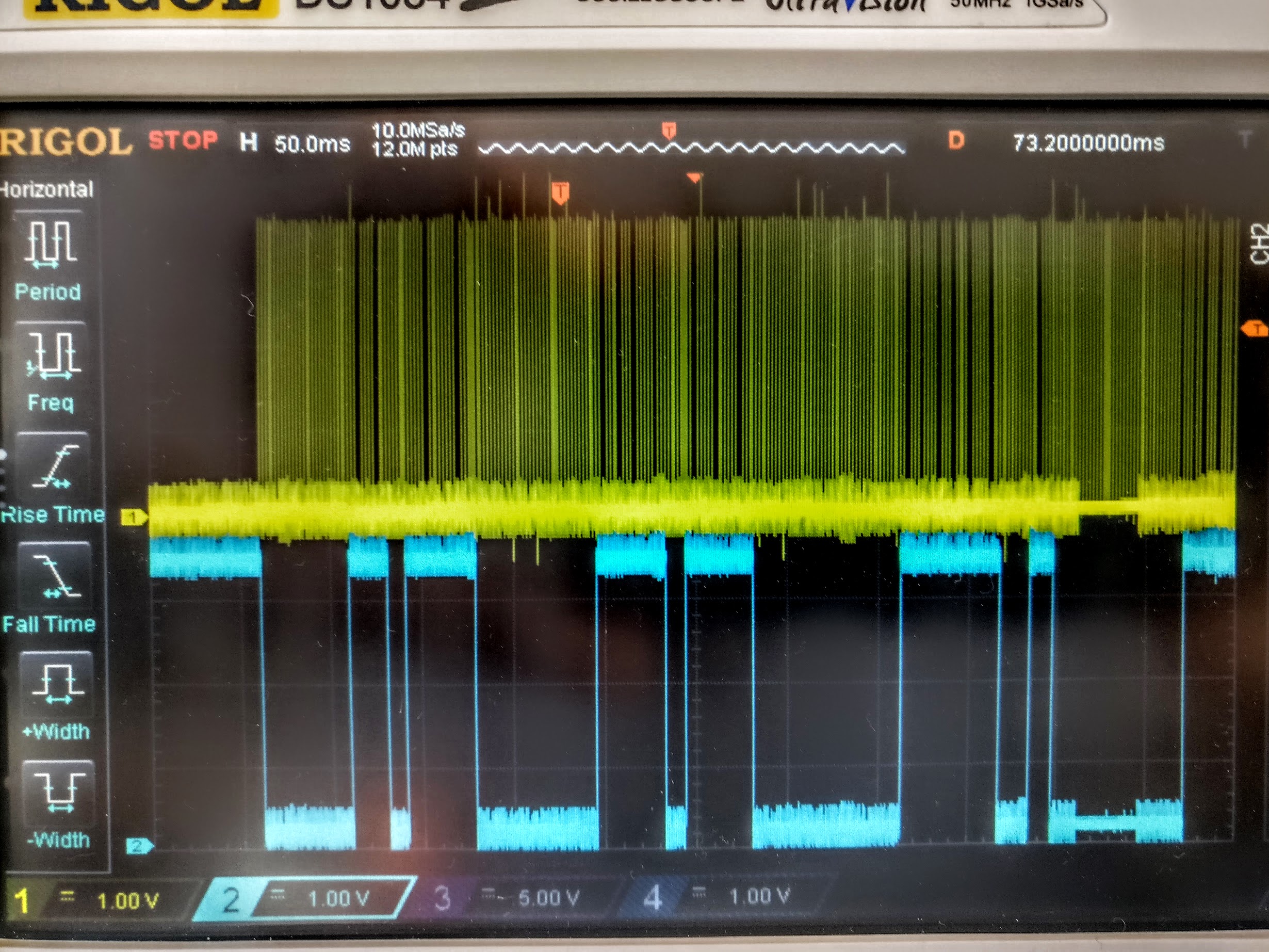
I've checked step/dir signals on the extruder and it confirmed that it frequently changes motor direction
Rattling happens regardless of what I print. Even when printing LIN_ADVANCE calibration pattern extruder starts rattling as soon as LIN_ADVANCE is enabled.
Despite the noise the printer is printing OK. At least, I don't see anything obviously wrong with the print, but the noise is rather bad. It's way worse when I had LIN_ADVANCE 1.0 working on the same printer. With 1.0 extruder was making 'tat-tat-tat-tat' noises. Now it's 'drrrrrrrrrrrr'.
I'm not quite sure whether that's working as intended (on close examination of the result there is a slight improvement in print quality), whether it's a problem with my config, or if it's something unexpected in LIN_ADVANCE implementation.
Steps to Reproduce
Expected behavior: [What you expect to happen]
LIN_ADVANCE 1.5 is supposed to
ensure a smooth extruder movement without rattlingActual behavior: [What actually happens]
Instead, the smooth movement with no retractions turns into constant back-and-forth.
Additional Information
Here is the album with the videos and oscilloscope shots demonstrating the problem:

https://photos.app.goo.gl/l8hzKHgBgaR0dw5I2
This is what is the extruder step(yellow)/dir(blue) signals look with LIN_ADVANCE disabled.
Here's what I get with LIN_ADVANCE enabled:
Marlin config files: Marlin-configs.zip
G-code for the test cube I've been printing: xyzCalibration_cube-gcode.zip
The text was updated successfully, but these errors were encountered: