[FR] M592 From RepRapFirmware (nonlinear extrusion) #9852
Comments
|
Marlin's |
|
Yes i know, but does it really compensate for speed extrusion error when extruder just does not extruder the needed amount of filament? |
|
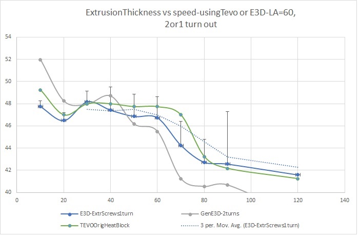
For clarification: Here is my test |
|
@ArtemKuchin for me it's not clear what you try to compensate. Is it for slipping hobbed bolt? You table in the link is also confusing for me, at 360mm/min you got 1.13g, at 60mm/min you got only 0.69g? Doesn't make much sense to me, if something is slipping it should be the opposite way round. If it's slipping, that's something that has to be solved by hardware in my opinion. I never had a problem with slipping drive gears, at every volumetric speed I ever tried the limit was Marlin calculation speed in most cases and only if I realy push it to extreme I'm hitting the melt capabilities of my hotend. In both cases, adjusting esteps/mm will not help. |
|
In short. Linear advance is another pair of shoes. It deals with a delayed reaction of outflow when extrusion speed changes - not the absolute amount. |
|
Presumably the issue has to do with the expansion of the filament, where at high speeds it might not expand as much. It sounds like something that would be sort-of akin to a long Bowden tube adding more flexibility to the drive. |
|
The different steps/mm seem to be measurable at the input side of the extruder. |
|
From what I've read online it is attributed to what amounts to "slipping" (or "missing") the teeth on an extruder that has a typical MK8-style drive wheel. I'm sure it doesn't affect a Bondtech Extruder, where there is constant grip. But if there are gaps between the points where grip can occur, I can see how the filament might "spring back" between those points, especially as pressure builds up. |
|
@Sebastianv650 The described effect is observable on both direct drive, geared and belted extruders with hobbed bolts and with toothed wheels, direct or Bowden. No matter how tight the extruder is. All people who actually did the test see then actual extruded length depends on extrusion speed. The physics behind this is not 100% clear. You can read the forum post i provided and links from there. People did the graphs to see the correlation. About 1.13g - plase, look carefully. 1.13 is mm - it is diameter, weight is 0.54-0.55g @AnHardt Not some, but everyone i know who did the tests. Maybe others just don't have the tools, time or will. or don't care. @thinkyhead I did not read about Bondtech, pretty rare beast and don;t know how it works, but the problem is very much present on E3D titan and on belted extruders. Also, if that was slipping then tightening the extruder should at least do some change, but no, in my test tightening the extruded results exactly in the same numbers. So, there was no slipping. I have direct extrusion extruder (not Bowden) and see the effect very much. BTW: Where did you read that online? Also, note than the problem is present for at least PLA and ABS filament types. I tested only PLA. Have SBS (softer, more like stiff rubber, 220C printe T) also, will test and see if the graph form is the same. |
|
Could it be that the material extruded at higher speeds is simply denser and less spongy at the microscopic level? And if so, how does this effect manifest in different materials? Perhaps we can do tests and actually weigh the filament that is extruded down to the milligram. If the weight-per-length is different that would fit the hypothesis. |
|
@thinkyhead i will test PLA vs SBS today on non-print extrusion and weight to 10s of milligram. My scales have 0.01 accuracy and resolution. |
|
Okay, did synthetic tests with SBS and real prints. L - extrusion length, also, how many times and pause time L can be just number (400) - which is mm SBS is very flexible filament. Has very low friction and good flow. But look, if extrude the same amount in 4 to 8 segments with pauses the problem goes away. So, it seems like pressure build up. Then i though. Well, how does it behave in real print. And i printed a test cube 20x20x10 with 80% infill As i thought, since there is accelatation/decelation happens pretty often the pressure does not build up. I have to notice here that i do not know the correct weight because at 40mm/sec there is a possibility of overextrusion. It it just a relative comparison point. This is a test for SBS. For PLA, i am sure, the result will be mode dramatic as it does not flow very well and pressure builds up faster and stronger. The filament feed rate in test prints. For speed 80mm/sec: 9.3 mm/sec PLA at 200C starts to skip at 6mm/sec. SBS at 220C does not skip until 9mm/sec contstant extrusion, but does not skip at real print (too short extrusion). ABS should be somewhere in between. So, it seems like for models with many corners and not so long lines the problem virtually not present. However, for models with longer walls it does pose a problem. |
|
Hmm, so that's a small difference, but still significant. A 2% reduction in mass at double the speed. I find it mildly amusing that the solution is to feed more into the extruder, thus increasing the pressure even more. But, it is perfectly sensible to mitigate against this effect nevertheless. I'll see about adding
|
|
2% is for SBS, which flows very well. Probably even less error for TPU, for example. Implementing the formula will be a good start. But i think it is wrong way. Good first order (even half order :) approximation, but not nearly as accurate as it should be. The error here that at start, when pressure in the nozzle is low no compensation is needed at all. If speed was reduced then pressure also dropped and less compensation is needed. So. the formula probably helps, but will give error. The formula considers the Vneeded as a function of Vspecified However, i still need to see the test prints with LIN ADVANCE enabled. As it allowed pressure release before decelaration, so, any extra buildup will be naturally release as overextrusion in some places, but it might the error amount of error as formula provides or even less with finely tune V and K. The paradox that we need to increase pressure to get the needed speed actually comes from the fact that we are printing to fast. If we printed at speeds at which pressure cannot build up we would not have such problem. Or at least at speed where problem is not noticeable. But it is too slow. For PLA and 0.4 nozzle probably up to of 30mm/sec. |
|
One more thought on test with LIN ADVANCE |
|
I still wonder if How does the temperature behave during your tests? |
|
By the way #if ENABLED(AUTOTEMP)
void Planner::autotemp_M104_M109() {
autotemp_enabled = parser.seen('F');
if (autotemp_enabled) autotemp_factor = parser.value_celsius_diff();
if (parser.seen('S')) autotemp_min = parser.value_celsius();
if (parser.seen('B')) autotemp_max = parser.value_celsius();
}
#endif
|
|
@AnHardt I was observing temperature in the tests, also was expecting some drop, but no, T is very stable. |
Exactly what I thought 👍 If this is caused by some material creeping due to the extrusion force, the extrusion velocity is an indication but only part of the problem. Regarding autotemp, I'm not too optimistic. Speeds are changing within seconds from infill to perimeter for example, while our hotends are quite lazy. And the time amount for look-ahead with a 16 blocks buffer can be very low. |
|
|

|
Here's some real world data and a simple method to calibrate/check that should further prove the utility of this feature. I measured the amount of 1.75mm PLA filament actually extruded on an Ender 3 at various extrusion speeds (on the extruder side!) when the hotend is at 210C (at which I get good adhesion and barely any strings). I'm using a stock Ender 3 calibrated earlier at 95 Esteps / mm and marking the filament at 130mm away from the extruder, sending the G92 E0; G1 E100 Fspeed command to extrude 100mm then measuring the distance to the filament mark I made earlier (as is done in usual extruder / ESteps calibration guides). Meanwhile I'm checking that the extruder gear doesn't skip (it didn't seem to). I've tried to be as consistent as possible including around timing which affects amount of oozing. Requesting extruding 100mm, I get at: This partly explains the weird combination of over-extruding (small walls on full bottom layers) and under-extruding (larger inner walls at 50mm/s) I've gotten in my test prints. Even a simple "extrude 0.00025 * speed more per mm" would bring down the extrusion errors from 2% to 5-10x less and allow for a later good extrusion rate/flow calibration (set in the slicer). Final note: I believe I'm getting more linear like results than SimonSolar2C since there are fewer variables at play in my test setup than in theirs. |
|
Someone in this thread mentioned that the cause of the issue is unknown. Well, in http://www.extrudable.me/2013/04/18/exploring-extrusion-variability-and-limits/ a photo is provided which shows that the teeth marks get closer when the filament is pushed faster. |
It's my understanding that the springiness of the filament and the increased back-pressure of faster motion causes a more pronounced spring back (or slippage) as the filament is pushed at a faster rate. You can test this theory by instead lowering the hotend temperature so that the filament is harder to push, and you should see the same symptom, with the tooth-marks getting closer together as the temperature gets lower. |
|
Guys, I came across this thread and I decided I wanted to add nonlinear extrusion to Marlin and do some real world testing. Maybe I will make a PR if it works well. My goal is transparently supporting M592 in the same way as Duet I am halfway there, I have added the M592 command to the command parser, and Im comfortable enough in C++ to find a place to store the parameters and stuff (I am also looking at the Duet3D RepRap firmware code which is also on Github, and the command parser is similar, so its pretty easy) But I need to know exactly where in the Marlin code to tie the nonlinear extrusion values into the extruder speed. The movement planner looks kind of complex. Im afraid I'm going to break my printer with a ridiculous movement. It should be a really simple addition, in Duet3d it is only a few lines. I was hoping some guru could just point me to the exact spot. For reference in Duet3D it does this (just to show how easy it should be) I am working from the 1.1.9 marlin code. |
Do you have a git repo for your changes? |
|
I made this post a while ago, and no one replied to it so I moved on to other things. I am still interested in having this feature and I have a CR-10 to test ideas on, but I was unable to confidently locate the part of the code to actually change and I was too nervous to totally screw up the motion of my printer. What we need to move forward is for someone to locate the line of code inside the movement planner that needs to be changed. Its really a simple request to someone who understands the movement planner, and I can make a repro with code once we have and idea of what changes to actually make. I dont know if we can tag someone for visibility here? Obviously this thread is inactive and no one has read it in a year |
|
A PR has been opened for this feature: |
|
(Sorry, I do see this issue is already closed :)) |
|
Im receiving updates because I requested this feature years ago. I would
agree with the point about maximum flow. I have had no trouble with flow
once I started using the "flow" view in Cura to understand the maximum flow
of my print head and slice prints accordingly
…On Wed, Aug 2, 2023 at 9:06 AM KimmoHop ***@***.***> wrote:
(Sorry, I do see this issue is already closed :))
I'm surprised none raised CNC Kitchen (YT) and his tests.
IMO correction is already on a slippery slope, and as each hotend-extruder
combo has maximum flow and slip will increase as it is approached. Maximum
flow is "hard" limit, it can't be exceeded (without changing parts,
filament or nozzle temperature) no matter how much extrusion you request
for.
Correction might help in some (corner) cases, higher flowing hotend or
filament (or higher nozzle temperature) would work as well or better.
Extruder to some extent, but if filament does not have time to melt
properly, well, it's debatable :D
—
Reply to this email directly, view it on GitHub
<#9852 (comment)>,
or unsubscribe
<https://github.com/notifications/unsubscribe-auth/AHTCBFWLV73TFPKYKMBUPMLXTJGEVANCNFSM4ES2GB4Q>
.
You are receiving this because you commented.Message ID:
***@***.***>
|
|
@KimmoHop what are your concerns about doing this sort of correction? Of course you can't use it to exceed the point where your extruder starts misbehaving or skipping, but I and others (including CNC Kitchen) have data that show that underextrusion starts well before that point. For whatever reason that occurs (heat flow issues, backpressure, gears slipping on filament, gears compressing filament, etc.) it can be corrected fairly easily. My experience with my implementation of this feature has been very good so far, especially with flexible materials like TPU. @timmeh87 not sure how you can fix "flow" by looking at the flow view in your slicer, but if you don't have any problems any more, great! It would still be great if others could try it out now that there's an implementation, so we can get more data on the usefulness of the feature and the model parameterization we should use. I have only 1 printer with 1 extruder and can't predict how other extruders (especially Bowden setups!) will behave. |
|
@abortz wouldn't that increase internal stress in resulting parts? If conditions are the same (i.e. temperature, hotend, extruder, plastic, etc are not changing) and only variable is extrusion speed, then reduction in plastic that exits the nozzle likely caused by the fact that plastic doesn't absorb heat as quick anymore and viscosity is reduced. If less plastic getting extruded, then what's probably happening is pressure build up inside the nozzle. When you try to push harder to compensate for underextrusion, you increase amount of plastic, sure, but that doesn't resolve core issue that introduces underextrusion. But that potentially introduces additional stress which might make parts prone to warping and stuff like that. I am not sure what would be a "real" solution to this but if lower viscosity is the reason, then compensation should be done by providing more heat to the plastic. Since MPCTEMP already does somewhat physically correct temperature modelling, I guess @tombrazier might have a thing or two to say about that too. |
|
@gudvinr I see. That is definitely an alternate hypothesis for what's going on. Even if everything is working ideally though, I think we still expect to see increased pressure inside the nozzle area due to the higher flow rate. My operating assumption has been that this increased pressure is interfering with the extruder's ability to push filament, somehow. Possibly slipping of gears on filament, or compression of filament between gear teeth or between the extruder and the hot area. If the problem is purely upstream of the hot area, then just pushing more material shouldn't introduce any new issues. My testing has already been with MPCTEMP enabled and the correct heat capacities for filaments, and is for relatively steady-state extrusions (100mm at constant speed), so I doubt there's a good fix for this at the temperature level. Besides, temperature control seems way to slow to deal with changing extrusion speeds. I think if its a heat flow issue as you hypothesize, and just pushing the right amount of material through the nozzle causes print quality issues, then the problem is just unsolvable by software. I haven't seen increased stress or warping, but I don't have nearly enough data, and my extruder setup only requires modest nonlinear compensation values. I'd be really interested to see data for a standard- vs CHT-style nozzle, which in theory has much better heat transfer to the filament! |
|
If you want to see data, then check out Stefan's videos on youtube,
CNCKitchen. Afaik he does not use any tricks when he makes the graphs of
flow in this video, its just straight extruder speed to flow on the X and Y
axes
https://www.cnckitchen.com/blog/bondtech-cht-high-flow-nozzle-reviewed
…On Sun, Aug 13, 2023 at 12:01 PM Andrew Bortz ***@***.***> wrote:
@gudvinr <https://github.com/gudvinr> I see. That is definitely an
alternate hypothesis for what's going on.
Even if everything is working ideally though, I think we still expect to
see increased pressure inside the nozzle area due to the higher flow rate.
My operating assumption has been that this increased pressure is
interfering with the extruder's ability to push filament, somehow. Possibly
slipping of gears on filament, or compression of filament between gear
teeth or between the extruder and the hot area.
My testing has already been with MPCTEMP enabled and the correct heat
capacities for filaments, and is for relatively steady-state extrusions
(100mm at constant speed), so I doubt there's a good fix for this at the
temperature level. Besides, temperature control seems way to slow to deal
with changing extrusion speeds. I think if its a heat flow issue as you
hypothesize, and just pushing the right amount of material through the
nozzle causes print quality issues, then the problem is just unsolvable by
software. I haven't seen increased stress or warping, but I don't have
nearly enough data, and my extruder setup only requires modest nonlinear
compensation values.
I'd be really interested to see data for a standard- vs CHT-style nozzle,
which in theory has much better heat transfer to the filament!
—
Reply to this email directly, view it on GitHub
<#9852 (comment)>,
or unsubscribe
<https://github.com/notifications/unsubscribe-auth/AHTCBFQCBLB7BIT72GIJ4R3XVD26VANCNFSM4ES2GB4Q>
.
You are receiving this because you were mentioned.Message ID:
***@***.***>
|
I think you're correct about that. Pumping power won't help with that due to it being very slow. Maybe CHC will have better responsiveness but cooling back to normal after you ramp up power will be slow in either case. In that case, since we only care about filament being adequately viscous, I wonder if better model is possible.
I am not sure how exactly it is done there. But maybe on higher feed rates it's just not aggressive enough? |
|
I believe there are two different effects going on, which are visible in the videos that Stefan and others have made. It is particularly apparent in the blue line in this screenshot from one of Stefan's videos
Up until about 30mm^3/s there is a gradual drop-off in flow rate as nozzle pressure builds. This is the back pressure from squeezing melted plastic through a small hole and is, in fact, the pressure that linear advance creates to ensure even flow. After 30mm^3/s there is a sudden extra drop in flow rate. I think this is where the unmelted core begins to reach the nozzle and block it and it is far more aggressive, like turning off a tap. Attempting to force not-fully-melted filament through the nozzle will likely result in stresses in the part which will cause bad prints even if you manage to get the extrusion rate you wanted. Stefan suggests in one of his videos that this is why his meander prints fail at high extrusion rates. I suspect this PR is best for targeting the earlier, more gradual slope. As it happens I have an extruder which is particularly prone to reduced extrusion rate with increased back-pressure. I have recently done a lot of testing with variations on the VDE-100 and have found the same as Stefan. As pressure builds, flow rate reduces gradually but there comes a cut-off point where it starts to reduce dramatically. CHT helps resolve this problem by increasing heat transfer to the filament and, thereby, pushing the cut-off point to a higher flow rate. The same general shape of graph results but the cut-off point comes later. I have also observed, incidentally, that the Chinese CHT clones I have tried actually significantly increase back-pressure at lower flow rates. Even when modified to be more like the genuine CHT nozzles (i.e. with a sharp edge at the center between the three holes rather than a flat face) these nozzles are worse than normal nozzles at low flow rates. But at higher flow rates they perform a lot better. With the VDE-100 it is fairly easy to see why flow rate decreases with back-pressure. The VDE-100 acts like a die, tapping a helical thread onto the filament and then using this thread to feed the filament like a screw. As back pressure increases, the shape of the helical groove widens. More and more instead of feeding filament, the extruder distorts the filament and if back pressure is high enough flow stops entirely and the extruder just makes a circular ring around the perimeter of the filament. It looks like the result of a plough wheel cutting through a field, with a plouged groove running parallel to a mound of material that has been pushed out of the furrow. I suspect a close examination of the pattern left by a toothed drive gear would show something similar. (In defence of VDE-100 I should add that I now have a design that has a lot more actual contact with the filament and which performs more like gear extruders. But that's another story.) Moving on, the flow rate modelling in MPC exists for temperature stability, not to increase heat transfer to the filament. When filament melts, it absorbs heat. The more filament that is melting, the more heat that is absorbed and so the more power that needs to be delivered to the heater. Rather than waiting for the nozzle to cool because of increased rate of melting and only then responding by increasing power, MPC increases it straight away, knowing that it is going to be needed. The |

|
Yup @tombrazier, Stefan's graphs are actually very deceptive due to the choice of axis. If you actually graph commanded vs actual flow rate, where his graphs take a sharp dive, you'll frequently see that the actual flow rate flattens or even goes down relative to the last data point, despite higher commanded flow rate. This is almost certainly a different effect than what was happening at lower flow rates, and regardless, why would you ever try to operate in that regime? You could get the same actual flow rate with a lower commanded one, and less weirdness to boot. :-) |
|
I saw this too. If fact when I pushed the limits, I would tend to get an oscillation where the flow rate would repeatedly drop and then increase again once I commanded it past a certain limit. My guess is that unmelted filament closed the hole in the nozzle, which caused back-pressure to build up until the extrusion became very slow, distorting the helical thread and causing the cutting edge briefly to get stuck in the rut that was created. This gave time for the unmelted filament to melt and extrusion then resumed and the cycle repeated. I could imagine a geared extruder getting to the point where it was stripping filament thus reducing extrusion force for a short time and causing the same kind of oscillation. |
|
The main benefit of nonlinear extrusion/M592 is allowing for higher quality prints even when using higher than usual extrusion flows. I.e. better quality (in this case means much reduced under-extrusion when printing fast) for faster prints. It will NOT allow pushing past nozzle extrusion limits (which seem highly discussed and focused on in this thread). I've measured the extrusion flow vs extrusion speed on my Ender-3 (modded, bimetal heat break, high temp thermal paste) and plotted it. The test procedure is basically the same as CNCKitchen's - extrude then weigh the sample with a 0.01g scale.
My 0.4mm and 0.6mm nozzles look limited to 15mm^3/s and 20mm^3/s respectively (at a ~normal printing temperature). For up to those extrusion speeds values only I've done a manual linear fit (i.e. M592 Aonly) and quadratic fit (M592 Bonly, seems to fit slightly better). Regardless of options, either way M592 could correct most if not all the currently significant under-extrusion at close to 15mm^3/s extrusion speeds. |

|
Mihai is your X axis in commanded speed or actual speed? I suspect commanded speed. |
|
It must be commanded speed, if the plastic was actually measured to be
moving at that speed then where does the rest of it go??? It cant bypass
the nozzle.
…On Mon, Aug 14, 2023 at 6:35 AM tombrazier ***@***.***> wrote:
Mihai is your X axis in commanded speed or actual speed? I suspect
commanded speed.
—
Reply to this email directly, view it on GitHub
<#9852 (comment)>,
or unsubscribe
<https://github.com/notifications/unsubscribe-auth/AHTCBFSOWYBTW676LKWDIJLXVH5N5ANCNFSM4ES2GB4Q>
.
You are receiving this because you were mentioned.Message ID:
***@***.***>
|
|
@tombrazier Yes, the graph X axis is in commanded speed (/flow). I have a dual gear extruder so even I was surprised that (on the data points shown) the extruder motor wasn't skipping. I thought that would be the weakest link. |
|
It has suddenly occurred to me that I have been being unfair to my VDE-100 extruder. I have been measuring underextrusion against actual flow rate. Here's a graph showing various permutations of the VDE-100 against commanded flow rate in mm^3/2:
The best one compares reasonably well with Mihai's data and that's with a clone CHT nozzle which has higher back pressure at lower flow rates. |

|
@thisiskeithb Can this issue be re-opened? #26127 is not merged in yet. |
|
Feature requests are closed when related PRs are opened. If there are issues with code in the proposed PR, please post comments over there. |
|
This issue has been automatically locked since there has not been any recent activity after it was closed. Please open a new issue for related bugs. |
Just discovered the problem with extrusion error vs extrusion speed on my own experience.
See discussion
http://forums.reprap.org/read.php?262,802277
Don't have any option other than to print at low speeds at least for external perimeters to get better quality.
RepRap firmware guys did M592 for nonlinear extrusion compensation.
Hope such thing will be implemented in Marlin.
http://reprap.org/wiki/G-code
“
Most extruder drives use toothed shafts to grip the filament and drive it through the hot end. As the extrusion speed increases, so does the back pressure from the hot end, and the increased back pressure causes the amount of filament extruded per step taken by the extruder stepper motor to reduce. This may be because at high back pressures, each tooth compresses and skates over the surface of the filament for longer before it manages to bite. See forum post http://forums.reprap.org/read.php?262,802277 and the graph at http://forums.reprap.org/file.php?262,file=100851,filename=graph.JPG for an example.
Nonlinear extrusion is an experimental feature in RepRapFirmware to compensate for this effect. The amount of extrusion requested is multiplied by (1 + MIN(L, Av + Bv^2)) where v is the requested extrusion speed (calculated from the actual speed at which the move will take place) in mm/sec.
Nonlinear extrusion is not applied to extruder-only movements such as retractions and filament loading.
”
The text was updated successfully, but these errors were encountered: