32-bit_adderRead Me Adder Circuits.pdf
Note: 4-bit adder-subtractor digital circuit files are also provided.
Note: All the circuits created for this project were done so utilizing the program “Digital” and can be run and modified utilizing this program.
They will not run on any other application to my knowledge.
The files are recognized by their .dig extension.
The two main files to run are: 32_bit_adder.dig & Final_4bit_add_sub.dig but the smaller individual circuits may be run on their own or from within the final circuit designs by Right Clicking on the custom circuits and running them in their own individual window.
A copy of the software "Digital" can be obtained from the github link: https://github.com/hneemann/Digital
IMPORTANT: All files must remain in the same folder! Removing or moving any files from the final project will not allow the final circuits to run. They run as a package. The program looks for all initial circuits created that are utilized in larger circuit projects so removing any from the folder renders the newly created circuit inoperable and components may not appear in the circuit.
Warning: Do not save the folder on your Desktop or in the “Digital” software package folder. For some reason the program does not recognize folders created on my desktop or its own application folder, but does everywhere else. Not sure why.
Note: I do all my development on an M1 MacBook Pro. All the circuits run without issue on my computer.
Full Adder: this was initially created. I then created an 8-bit adder to test the Full Adder circuit for functionality when daisy chained together for larger circuit design. The Cin & Cout are required for the circuit to run. Cin is set to 0 and is the Carry bit for subsequent Full_Adder circuits....Cout being the Carry bit.
Full Adder Circuit:


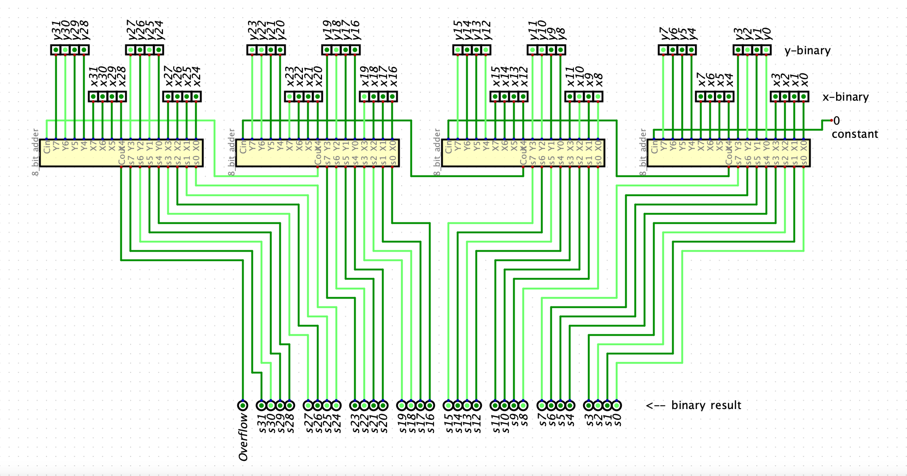
The 32-bit Binary Adder Circuit below was created utilizing 4 of the above 8-bit adder circuits. Right clicking on any of the “designed circuits” pulls up the underlying architecture of the circuit if you choose to do so and can also be run from their pop-up window if desired. I changed the initial Cin to a Constant input 0 in this circuit provided by the software rather than an input switch. This is set to a constant of 0.
The software itself unfortunately does not provide 1’s & 0’s to be indicated on the input & outputs, only Light & Dark.
Their indications are as follows: Light = 1 & Dark = 0
The Y input is read across the top row and X, the row below.

Exercise 2: This was built utilizing 4 Full Adder circuits and a mux preceded by a Not, this flips the bits for subtraction. The initial circuit was then miniaturized to a custom circuit and utilized for the final circuit design. When the “subtract” input is dark it is in “addition mode”. Depressing and lighting the subtract input converts the circuit into “subtraction mode”.
Note: Negative and Overflow are not accounted for in this circuit.
