Hardware Connection
An example of a hardware connection is given in Figure 1, which shows the connection of the RO, DI, RE* and DE lines of an RS485 transceiver to the Atmega/Arduino. Connecting the enable lines DE and RE* to separate pins of the Atmega/Arduino, gives the software full control over the communication via RS485.
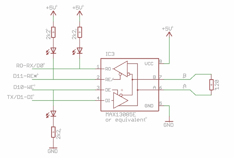 Figure 1.
The individual control of the RS485 enable lines allows for various modes of operation, such as collision detection (requiring read while write) or exclusive communication over RS232 (requiring disabled read, as enabling read from RS485 mutes the regular RS232 reception). Furthermore, the RE* pull-up circuit ensures that the RS485 read is disabled upon reset of the Atmega/Arduino, hence allowing program downloads in the usual way from the Arduino IDE. Note that, apart from the RE* pull up resistor, all other extra components in the above diagram are optional. However, the presence of the LEDs to indicate the receive/transmit status of the RS485 will, be very appreciated for diagnostics.
The RS485 circuit can be implemented on a breadboard (Figure 2), soldered onto a shield (Figure 3), or included into a new PCboard design (Figures 4).
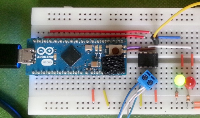
Figure 2. The simplest breadboard realization of the circuit shown in figure 1, based on the Arduino/Micro and a directly mounted RS485 transmitter IC.
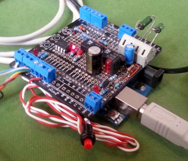
Figure 3. A more sophisticated implementation with additional circuitry based on the screw-shield. The RS485 interface IC is visible in the top-middle on the shield.
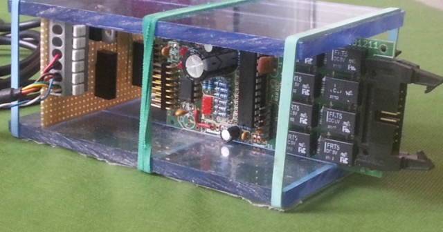
Figure 4. A prototype chassis with a primitive backplane connects two custom designed Atmega/Arduino PC boards to the RS485 bus.
Alternatively a circuit board containing a 485 interface can be procured from http://yourduino.com/sunshop2/index.php?l=product_detail&p=323 (see Figure 5). This board does not, however, contain the LEDs to indicate the status of the enable lines. More important, this board has a DE high pullup, (in contrast to the recommended configuration shown in figure 1), with the implication that upon start-up of the Arduino (all ports tri-stated), Data Transmission is enabled. As a consequence, the MAX485 will actively drive the RS485 bus, blocking any bus transmission. Hence, it is suggested to remove the DE pullup and to add an external pulldown resistor. Finally one should be aware that these interface boards contain a 120 ohm bus termination resistor, which is not a problem if used in point to point communications, but not in a multidrop environment, where only the extremities of the bus should be terminated.
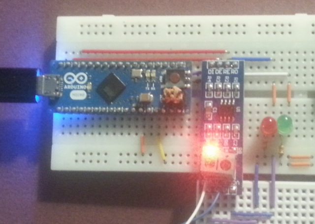
Figure 5. Breadboard version based on a small pc board with a premounted RS485 interface. Due to circuit failure in the RS485 PC boards (possibly following a manipulation error), this configuration was not fully tested.
Figure 6 shows the test setup used by the author to develop the HardwareSerialRS485 library, connecting together 6 RS485 devices (One RS485-USB connected to the PC, one Uno/ScrewShield, 50 m of cable, one Micro/breadboard, two custom boards, a second RS485-USB connected to the PC).
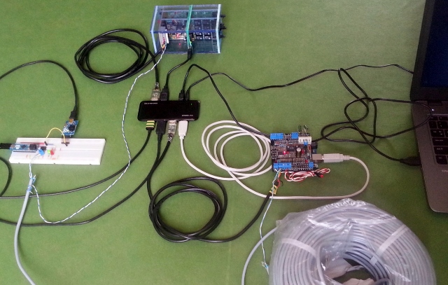 Figure 6.
- next: Software Capabilities