In order to support our work please consider supporting us by donation or purchase the dev kit board.
https://www.paypal.me/qwavesystems
https://qwavesys.bentoweb.com/en/product/346754/MelonS3?category_id=84967
https://www.facebook.com/groups/244230302736445/
- Introduction
- Specification
- System Block Diagram
- Board Overview
- ESP-PROG (TX/RX) Jumper Setting
- Pin Definition
- Getting Started
- OTA Programming (Upload .bit file to flash memory over the WiFi)
- Write your own ESP8266 firmware.
- FPGA Development using Xilinx ISE Webpack
- Install LabVIEW FPGA Driver
- LabVIEW FPGA: Demo (Debug Mode over WiFi)
- LabVIEW FPGA: Create a build specification to build a .bit file
- LabVIEW FPGA: Additional Tools
- LabVIEW FPGA: Export .bit file
- LabVIEW FPGA: Generate Control define for Arduino
- LabVIEW FPGA: Host-Target Architecture: (Arduino MCU) <-> (FPGA)
- LabVIEW FPGA: Host-Target Architecture: (Raspberry Pi CPU) <-> (FPGA)
- Mechanical Specification
- Download Board design files
- License
- Maintainer
The Melon S3 FPGA is an open-source hardware (OSHW), expandable development board perfect for the learning digital circuit design and prototyping of your unique ideas. You can customize the capabilities of the FPGA with snap-on 40-pin "Raspberry Pi HAT". There are serveral shilds in the market offers a low cost module that can be purchased off the shelf. These shiled modules can be plugged directly to the Melon S3 FPGA board for the creation of powerful embedded and digital system applications.
- OTA (Over-The-Air) Download.bit file to FPGA over the WiFi
- Xilinx Spartan 3E FPGA (PQG208) - 500K gates, (73Kb Distributed RAM, 4 Digital Clock Manager (DCM), 20 Multipliers (18x18), 360 Kb Block RAM)
- Onboard USB-UART (Silicon Labs) CP2104 for Configuration, Debugging and Power.
- MCU WROOM-02 (ESP8266), WiFi 2.4GHz + 32-bit MCU (Arduino Compatible) Clock 80MHz, 50KB RAM, Integrated TCP/IP protocol stack.
- Flash 4MB SPI Flash which is 1MB for MCU Firmware and 3MB for FPGA Bit space.
- 8 Users LEDs, 4 DIP Switch user button, 1 Reset button
- Onboard FPGA clock 50MHz
- GPIOs 56 PINs 3.3V Tolerant - 40 PINs x2 (Raspberry Pi 40 PINs Compatible)
- JTAG Port (*Optional for Program/Debugging)


In addition, The Melon S3 FPGA can be programmed using established development tools, such as Xilinx ISE (Free: Webpack), MATLAB HDL Coder/HDL Verifier and National Instruments LabVIEW FPGA Toolkit. Lastly, MCU ESP8266 (WROOM-02) can be programmed using Arduino IDE.
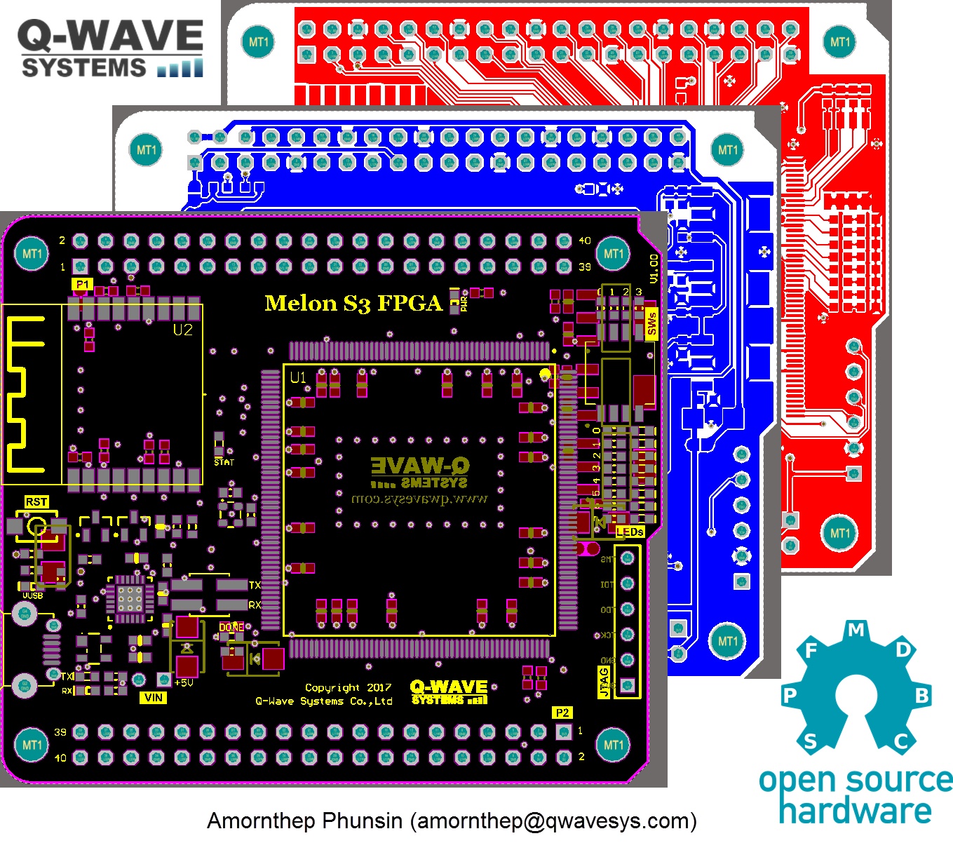
Front Side

| Position | Reference | Description |
|---|---|---|
| 1 | JTAG Port | Optional for Programing & Debuging using Xilinx ISE Software |
| 2 | FPGA | Xilinx FPGA Spartan 3E 500K |
| 3 | LEDs | x8 LED (Green) |
| 4 | DIP SWs | x4 DIP Switches |
| 5 | Pwr LED | 3.3V Power LED (Red) |
| 6 | XSTOP Jumper | FPGA code will STOP if Jumper added (Size 2.5"), Using this jumper as a FPGA stop pin (No jumper by default) |
| 7 | Status LED | User define LED (Green) at GPIO15 of ESP8266 |
| 8 | MCU | WiFi SoC (ESP8266) Flash 4MB Version |
| 9 | Oscilator | ABRACON 50 MHz onboard oscilator (50ppm) |
| 10 | LED1 | User define LED (Green) at GPIO2 of ESP8266, This LED will be flashing during upload firmware to ESP8266 |
| 11 | Reset Btn | Reset Button for ESP8266 |
| 12 | TX/RX Jumper | TX/RX Jumper of ESP8266 and USB CP2104 (Size 2.0"), Refer Jumper setting section |
| 13 | USB IC | CP2104 UART to USB IC |
| 14 | USB LED | USB Plug-in LED Status (VUSB) |
| 15 | Done LED | FPGA Status LED if .bit file downloaded to FPGA without error |
| 16 | VIN 5V | External Power supply +5V can powered the board from this pin |
| 17 | TX/RX LEDs | TX/RX LED Status of USB IC (CP2104) |
| 18 | USB Connector | USB Connector for +5V input for powered the board or Debug/Programming port for ESP8266 |
Bottom Side (Solder pad jumper for the users are willing to use with Raspberry Pi Shileds)

| Position | Reference | Description |
|---|---|---|
| 1 | (JP2) RPi 3.3 V Jumper | Solder pad Jumper is "Open" by Default, But once the Melon FPGA and Raspberry Pi Shields stacked together at P1 Port, You can powered RPi Shileds board at 3.3V P1:1,P1:17 (3V3_RP) by using the power VUSB (5V) or VIN (5V) from Melon FPGA board, by setting the Jumper "Closed (Soldered)", Refer schematic for more information |
| 2 | HSWAP Jumper | Set the default state of FPGA Pins, Solder pad jumper is "Open"= Pull-down (by Default), Set the jumper pad to "Closed, (Soldered)"= All the FPGA pins are Pull-Up. |
| 3 | (JP1) Rpi 5V Jumper | Solder pad Jumper is "Open" by Default, But once the Melon FPGA and Raspberry Pi Shields are stacked together at P1 Port, if you want to powered RPi Shields P1:2,P2:4 (5V_RP) by using the power VUSB (5V) or VIN (5V) from Melon FPGA board, by setting the Jumper "Closed (Soldered)", Refer schematic for more information |
"ESP-PROGRAM" TX/RX Jumper is set to "Open" by Default, In order to re-program ESP8266 firmware, The both jumpers (TX/RX) need to be inserted (Closed).
USB TX/RX and ESP TX/RX pins also routed to FPGA refer the diagram below, You can writed the FPGA code to set jumper internally. In this case you can re-program the ESP8266 firmware without any jumpers.


Port1
FPGA Pin Number (Pxx) vs Connector Pins (RPi shileds can be connected to this port)
| Description | Pin Number | Pin Number | Description |
|---|---|---|---|
| +3V3_RP Using with RPi shields need to set solder pad jumper at bottom side | 1 | 2 | +5V_RP Using with RPi shields need to set solder pad jumper at bottom side |
| P50 | 3 | 4 | +5V_RP Using with RPi shields need to set solder pad jumper at bottom side |
| P49 | 5 | 6 | Ground |
| P48 | 7 | 8 | P47 |
| Ground | 9 | 10 | P42 |
| P41 | 11 | 12 | P40 |
| P39 | 13 | 14 | Ground |
| P36 | 15 | 16 | P35 |
| +3V3_RP Using with RPi shields need to set solder pad jumper at bottom side | 17 | 18 | P34 |
| P35 | 19 | 20 | Ground |
| P31 | 21 | 22 | P30 |
| P29 | 23 | 24 | P28 |
| Ground | 25 | 26 | P25 |
| P24 | 27 | 28 | P23 |
| P22 | 29 | 30 | Ground |
| P19 | 31 | 32 | P18 |
| P16 | 33 | 34 | Ground |
| P15 | 35 | 36 | P12 |
| P11 | 37 | 38 | P9 |
| Ground | 39 | 40 | P8 |
Port 1 : The FPGA pin constraints (.ucf) for Xilinx ISE and FPGA IO for LabVIEW aslo provide.


Port2
FPGA Pin Number (Pxx) vs Connector Pins
| Description | Pin Number | Pin Number | Description |
|---|---|---|---|
| +3V3 | 1 | 2 | +5V |
| P153 | 3 | 4 | +5V |
| P152 | 5 | 6 | Ground |
| P150 | 7 | 8 | P151 |
| Ground | 9 | 10 | P147 |
| P146 | 11 | 12 | P145 |
| P144 | 13 | 14 | Ground |
| P139 | 15 | 16 | P140 |
| +3V3 | 17 | 18 | P138 |
| P137 | 19 | 20 | Ground |
| P133 | 21 | 22 | P132 |
| P129 | 23 | 24 | P128 |
| Ground | 25 | 26 | P127 |
| P126 | 27 | 28 | P123 |
| P122 | 29 | 30 | Ground |
| P120 | 31 | 32 | P119 |
| P116 | 33 | 34 | Ground |
| P115 | 35 | 36 | P113 |
| P112 | 37 | 38 | P109 |
| Ground | 39 | 40 | P108 |
Port 2 : The FPGA pin constraints (.ucf) for Xilinx ISE and FPGA IO for LabVIEW aslo provide.


- Plug-in the USB cable to the USB computer port to powered the board, You will get the 8-bit counter (up) at onboard LEDs with speed around 100ms.

- Debugging the data at COM port, Put the "ESP-PROG" both jumper to the "Closed" position,

- Open the Serial Monitor software > Select COM port > Set the buad rate to "115200",Then pressed the "RESET" button on the board. This is what you will get from serial monitor.

- Right now the board is act like WiFi Access Point name "Melon-xxxxx", Re-scanning the WiFi, its will be appear on the network.
- Connect to the "Melon-xxxxx" using the default password "88888888"
- After that open the web browser, Then goto main webpage "192.168.4.1"

-
There are several command that already created for you to working with File Systems over the web browser. It is written using Arduino C/C++ ,Refer to shipped firmware source code in this repository ("Firmware" folder).
- ./files (List the files inside flash memory)
- ./startup (Set the config file to load FPGA code at startup)
- ./unstartup (Unset the config file to load FPGA code at startup)
- ./delete?file=[File Name] (For example : http://192.168.4.1/delete?file=xx.bit)
- ./[File Name] To view or download the file (For example : http://192.168.4.1/xx.json)
-
For example we will try to lists the files that currently stored in flash memory. Type : "http://192.168.4.1/files You will see there are serveral files, The important one is "Fpga.bit" file, It's a FPGA bit file that currently running on the board right now.

- Download the .bit file from "Bit_File/Fpga.bit" from this repository. Save it in your local computer. (It is a .bit file of 8-bit counter circuit that shipped with the board)
- Click the "Choose File", > Select the "Fpga.bit". > Click "Update", The bit file will be transfer over the WiFi then upload diretly to flash memory, (You will get status "Update Success!", If it not please try again), After that board it will reset once, Finally you will see the FPGA start-up with the 8-bit counter circuit again.

- Download a Arduino IDE 1.8.x from "https://www.arduino.cc/en/Main/Software"
- Goto "File > Preferences", Then add "http://ftp.qwavesys.com/lvembedded/package_qwavesys_v2_index.json" > Click OK


- Goto "Tools > Board> Boards Manager ", Install "Embedded LabVIEW Arduino by Qwavesys"


- Once the installation finished, You can find the "Qwave ESP8266 (LabVIEW)" board.

-
The shipped Melon S3 MCU firmware is located at "Firmware/Firmware-MelonS3-v.0.3.ino" from this repository, Open it with Arduino IDE.
-
Let's modify the WiFi AP name to "Melon-[Your Name]" to indicate that this is your board in the WiFi network, You can change default password, if you want to..

-
In order to program ESP8266, The jumper setting must be in the right position, . In this case I will leave both jumpers opened (Removed), Because FPGA shipped example bit file is already routed ESP TX/EX <----> USB TX/RX inside FPGA chip. Refer jumber setting section. TX/RX Jumper Setting
-
Connect the board to development PC, Select "Qwave ESP8266 (LabVIEW)" board, Speed "921600" (Test with Max Speed,If it not working try reduce the speed down to 115200), Select COM port.


ISE® WebPACK™ design software is the industry´s only FREE, fully featured front-to-back FPGA design solution. ISE WebPACK is the ideal downloadable solution for FPGA and offering HDL synthesis and simulation, implementation, device fitting, and JTAG programming. ISE WebPACK delivers a complete, front-to-back design flow providing instant access to the ISE features and functionality at no cost. Xilinx has created a solution that allows convenient productivity by providing a design solution that is always up to date with error-free downloading and single file installation. After generated .bit file you can then upload it to the Melon S3 FPGA via WiFi.
-
The shipped example for Xilinx ISE VHDL project is located at "Example_VHDL/Test_LED.zip" from this repository, Open it with Xilinx ISE. Refer the setting below Spartan3E , XC3S500E, PQ208, Speed Grade (-4)
-
At the LED_SW.vhd, it is very simple VHDL example the reading the status of DIP switch and display at onboard LEDs.


- The Melon_S3.ucf files also provide for pin constraints.

- After run Synthesize > Translate > Place &Route > Generate bit file , Then you will get led_sw.bit, Please rename to "Fpga.bit", Then you can use OTA Programming (Upload .bit file to flash memory over the WiFi) method to download a bit file to flash memory and run at FPGA.

The NI LabVIEW FPGA Module extends the LabVIEW graphical development platform to target FPGAs. LabVIEW FPGA gives developers the ability to more efficiently and effectively design complex systems by providing a highly integrated development environment, a large ecosystem of IP libraries, a high-fidelity simulator, and debugging features.
-
Before install LabVIEW driver , Please close all LabVIEW application. In this tutorial is assumed that you already have LabVIEW 2014 (32bit) & LabVIEW 2014 FPGA Toolkit (For Windows) installed in local machine.
-
Extract the folder QwaveSys to path. "C:\Program Files (x86)\National Instruments\LabVIEW 2014\Targets\NI\FPGA\QwaveSys"

- Extract the folder "MelonS3" to path. "C:\Program Files (x86)\National Instruments\LabVIEW 2014\vi.lib\FPGAPlugInAG\Melon-S3"

- At Windows Dev Machine: Copy "QwaveFpgaLv.dll" to systems path. "C:\Windows\System32\QwaveFpgaLv.dll"

- Remove "resource_cache.xml" the file below, Before staring LabVIEW ONLY for the first time use. "C:\Program Files (x86)\National Instruments\LabVIEW 2014\Targets\NI\FPGA\resource_cache.xml"

- Extract the folder "HDL" to path. "C:\Program Files (x86)\National Instruments\LabVIEW 2014\rvi\HDL"

- Start LabVIEW > Create LabVIEW Empty Project, Under "My Computer" Select "Target and Device, you will find "Melon-S3" under "3rd Party group"


- Right click at "Melon-S3" select "New > FPGA I/O" you will find available IOs for Melon-S3 ready to use within the project. Add them all if you want.


-
The shipped example for LabVIEW FPGA is located at "Example_LabVIEW/Test_Counter.zip" from this repository, Open the project (LED.lvproj) file with LabVIEW.
-
Connect development PC with "Melon-S3-xx" WiFi AP. Refer to this step Getting Started
-
Clcik Run button, Then observed the LabVIEW front panel and Onboard LEDs, Then you can adjust the Count(mSec) value to see the result in debugging mode.

- Right Click at the VI (.vi) > Create Build Specification

- Under Build Specification > Right Click > Select : Properties

- Select Run when loaded to FPGA

- Right Click then, Select Build

- Select the Use the Local Compile server or Network/Cloud server. (NI LabVIEW 2014 FPGA Module Xilinx Compilation Tools for Windows is required for local compilation. After finished you will get the output bit file at "FPGA Bitfiles" folder.


-
Right Click at the VI you will get additional tools fo Melon S3 FPGA:
- Gen Bit File... (Generate a bit file from build specification)
- Download VI To Flash Memory (Download bit file to flash memory over WiFi, This will be done automatically.)
- Set FPGA Download As Startup (Set FPGA code at startup, This action will be set "startup=1" at config.json file)
- Unset FPGA Download As Startup (Unset FPGA code at startup, This action will be set "startup=0" at config.json file)
- Get Controls Define For Arduino (Lists all LabVIEW front panel/controls for Arduino interface, Refer more detail to the next topic) - Reboot To view or download the file (This will send FPGA "reboot" command to the Melon FPGA board)

- Select "Gen Bit File.." function, Then you will get Fpga.bit locaed at "FPGA Bitfiles" folder.

- Select "Get Controls Define For Arduino" function, Then you will get front panel control/indicator define to use in Arduino Code, Copy them and place at the top of Arduino C/C++ code. Refer next topic for example.


Using Arduino IDE you can write your own firmware running in MCU (WROOM-02), This allows your FPGA designs to talk to the microcontroller, giving you develop the MCU + FPGA for co-processing application.


PDF https://github.com/QWaveSystems/Melon_S3_FPGA/tree/master/PDF
Schematic & PCB https://github.com/QWaveSystems/Melon_S3_FPGA/tree/master/Schematic_PCB
Firmware (Arduino C/C++) https://github.com/QWaveSystems/Melon_S3_FPGA/tree/master/Firmware
Xilinx ISE support files
https://github.com/QWaveSystems/Melon_S3_FPGA/blob/master/UCF%20File/Melon_S3.ucf
Xilinx ISE project examples
https://github.com/QWaveSystems/Melon_S3_FPGA/tree/master/Example_VHDL
LabVIEW FPGA (2014) Examples
8 bit Counter Example https://github.com/QWaveSystems/Melon_S3_FPGA/tree/master/Example_LabVIEW
8 bit Counter with Raspberry Pi Interface https://github.com/QWaveSystems/Melon_S3_FPGA/tree/master/Example_LabVIEW_RaspberryPi_LINX
-Schematics and PCB files is licensed under a Creative Commons Attribution-ShareAlike 4.0 International License. You should have received a copy of the license along with this work. If not, see: http://creativecommons.org/licenses/by-sa/4.0
-These Arduino C/C++ ESP8266 microcontroller libraries (Firmware) files are provided under the GNU General Public License Version 3 as found at http://opensource.org/licenses/lgpl-3.0.html.
-Melon S3 FPGA Driver for LabVIEW is licensed for Home/Education use ONLY (Non-Commercial purposes), Refer license agreement License Agreement Melon S3.txt
Amornthep Phunsin amornthep@qwavesys.com