Build Instruction: TranspOtter
![]()
TranspOtter is an open source semi self driving transportation platform based on hoverboard hardware. Its targed audience is everyone ranging from urban living people to students and teachers. The main goal of this documentation is to enable the simple and cost-effective assembly of a TranspOtter.
Since TranspOtter is semi self-propelled, its use may be restricted, please check your local laws.
- Soldering Iron
- Basic screwdriver sets (Torx, Hexagon, Phillips, ...)
- Jigsaw
- (Cordless) Drill + Drills
- Wood (~400*600mm for the base)
- Hoverboard mainboard
- Two hoverboard motors
- Hoverboard battery
- Gametrak
- Various screws
- Wood glue
- Activate the
Linux Subsystem for Windows. Further instructions on how to do that can be found here. - Install the
UbuntuApp from the Microsoft Store. - Open the
Ubuntushell from the start menu and follow the instructions. - Now install the arm-gcc toolchain and the build-essential by entering the following three commands into the ubuntu shell:
sudo add-apt-repository ppa:team-gcc-arm-embedded/ppasudo apt updatesudo apt install gcc-arm-embedded build-essential - To flash the firmware to the mainboard, you need to download and install the "ST-Link Utility for Windows" from ST.
Scroll down to the bottom and get the "STSW-LINK004" file.
- Install the arm-gcc toolchain by entering the following commands:
sudo add-apt-repository ppa:team-gcc-arm-embedded/ppasudo apt updatesudo apt install gcc-arm-embedded build-essential openocd - Also download and install the
stlinktool from GitHub.
- Install the arm-gcc toolchain by entering the following command:
pacaur -Sy arm-none-eabi-gcc openocd
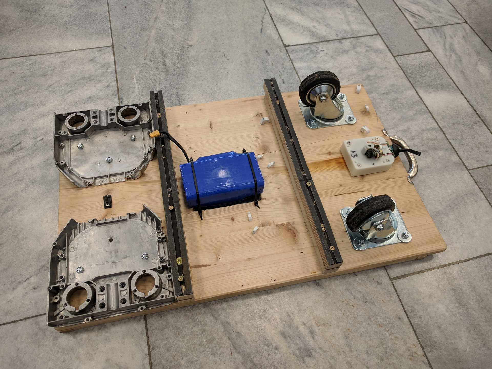
The chassis of transpOtter may consist of wood that is cut to size. The recommended dimension is 400x600mm as this is the format of Euro crates or two beverage crates. To prevent boxes and crates from sliding off the chassis, a border frame with an internal size of 380x580mm and a height of 10mm can be glued on.
 (The handle is additional)
Next to the slot for the crates, a cutout can be milled for the battery. That makes the transpOtter much flatter.
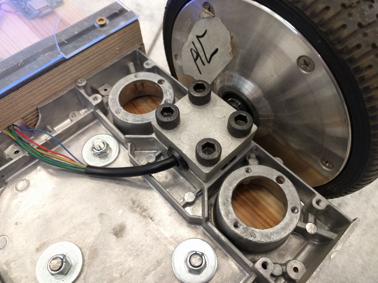
The original Hoverboard frame can be used as motor brackets. The bracket must be cut to size as these are far too wide.
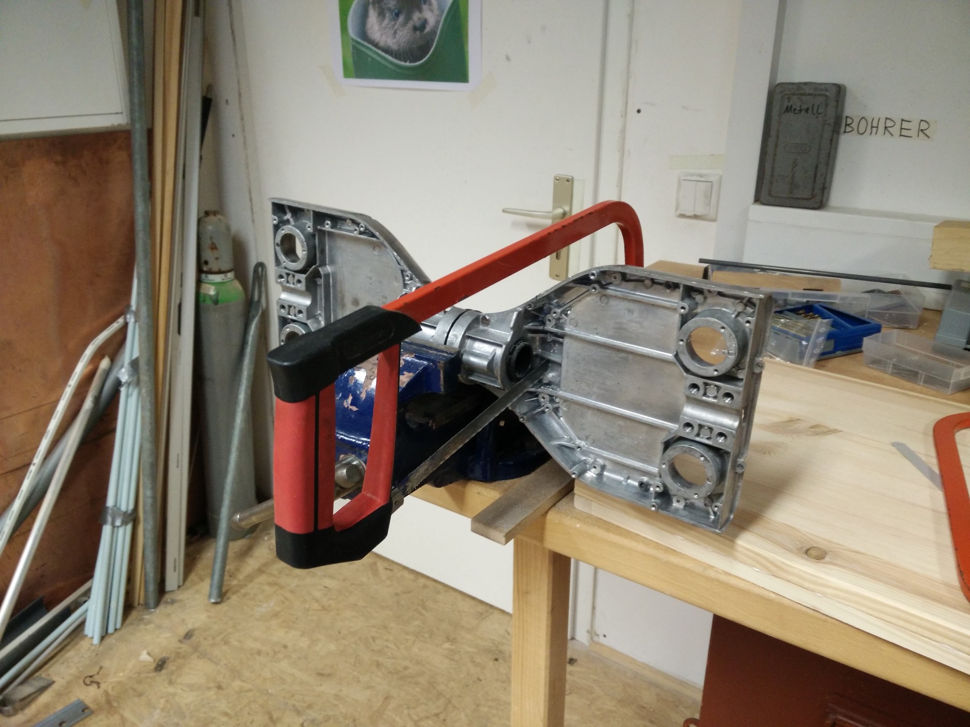
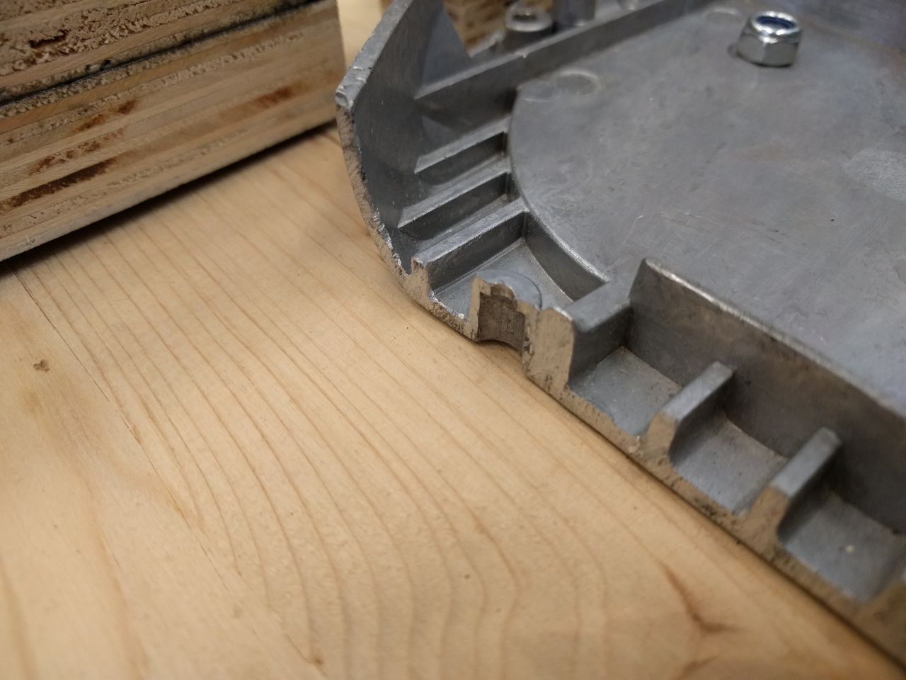
This can be accomplished with a hacksaw. In the next step at least three holes with a diameter of 8mm should be drilled. These will be used for mounting the bracket to the base.
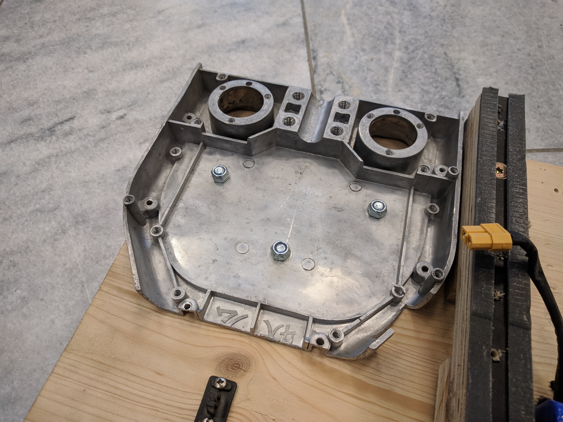
Brackets should be deburred to protect the wiring.
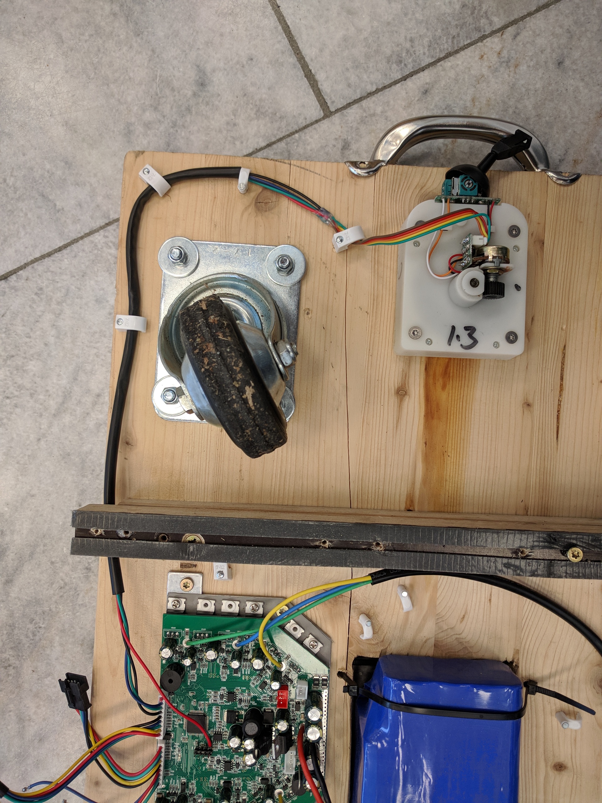
Now the motors and wheels can be mounted to the base. To do this, you will need to drill a few holes accordingly to the mounting holes present in the motor brackets and wheels.
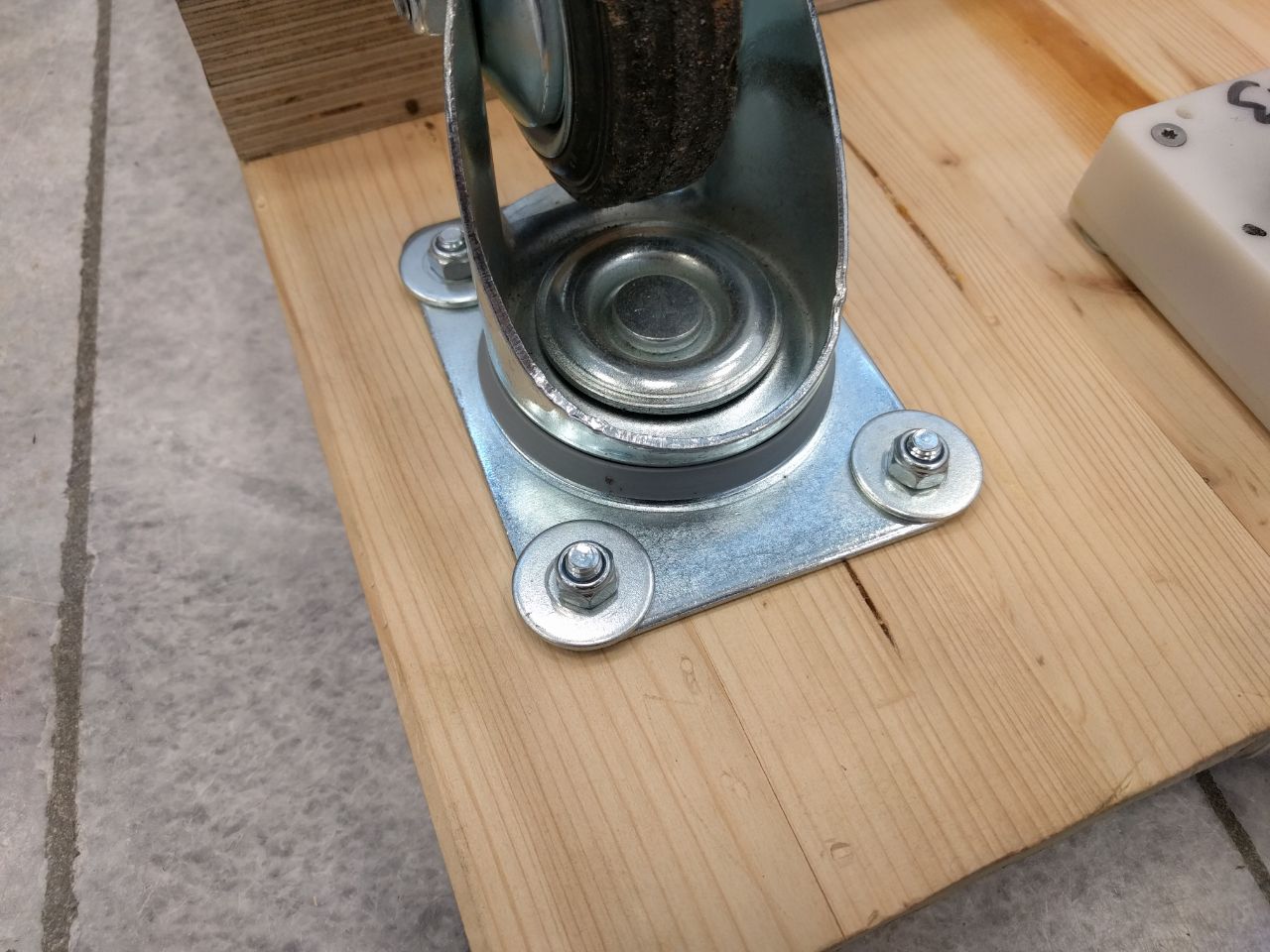
The Motor will be held by the original motor mount.
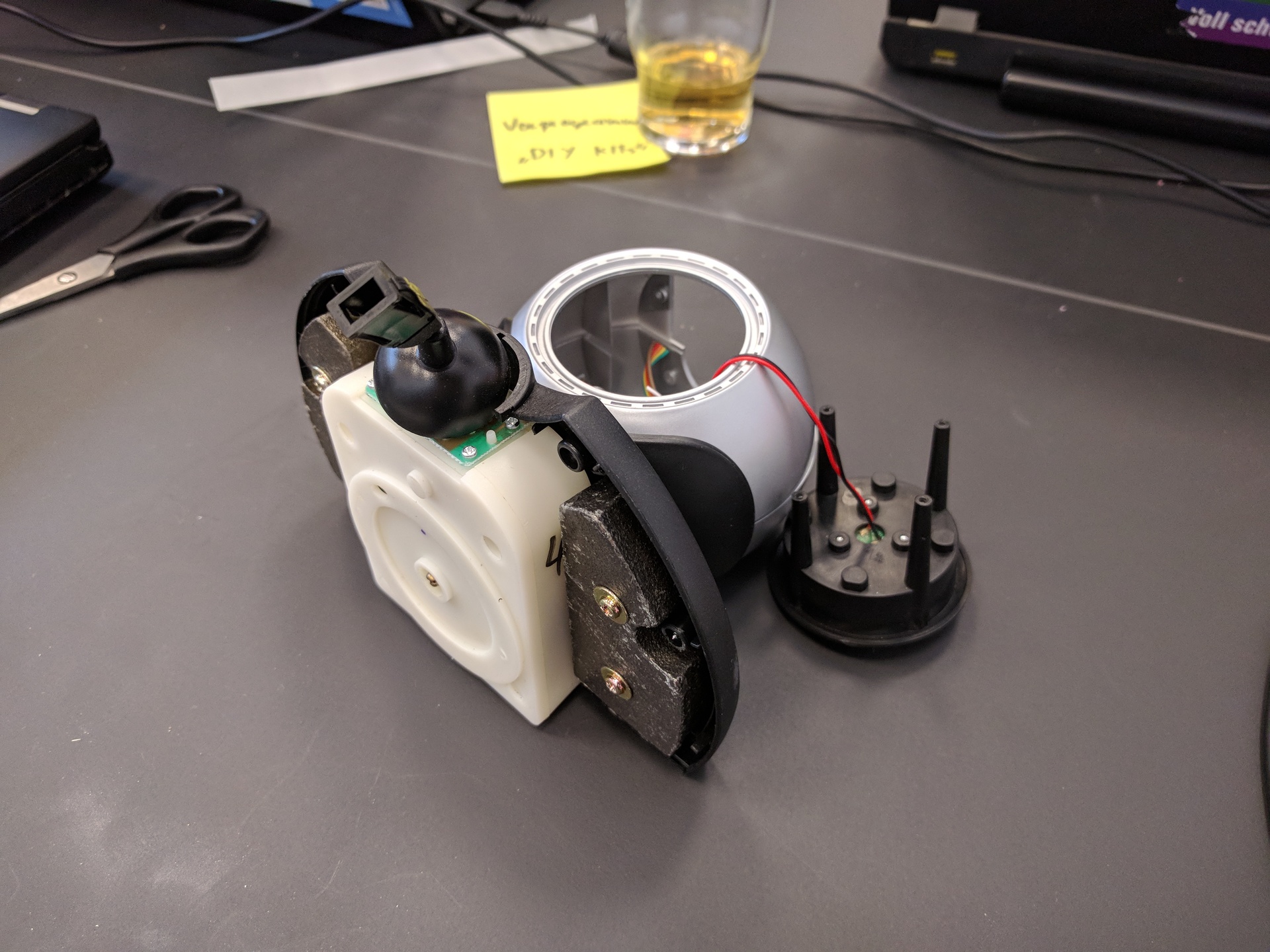
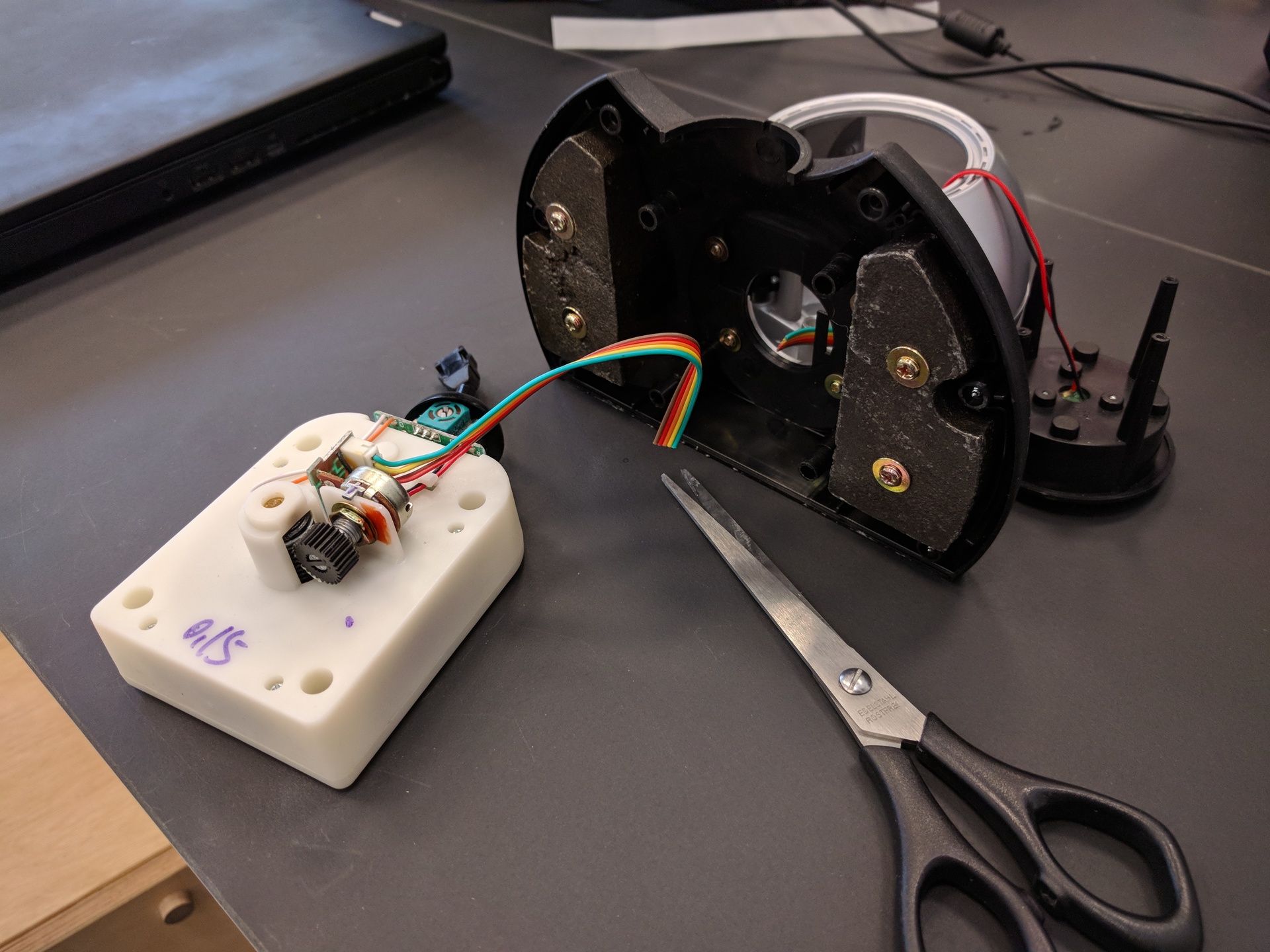
The Gametrak mechanics can be obtained from a Playstation 2 Gametrak Playstation 2 Gametrak Controller, each controller contains two Gametrak mechanics.

To open the Gametrak, six screws need to be unscrewd per side. The cable to the mechanic can be cut.
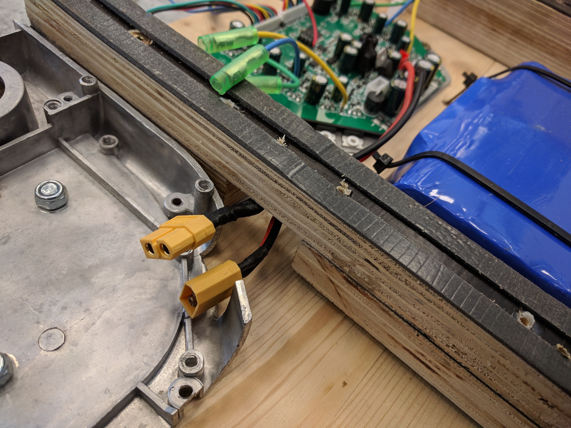
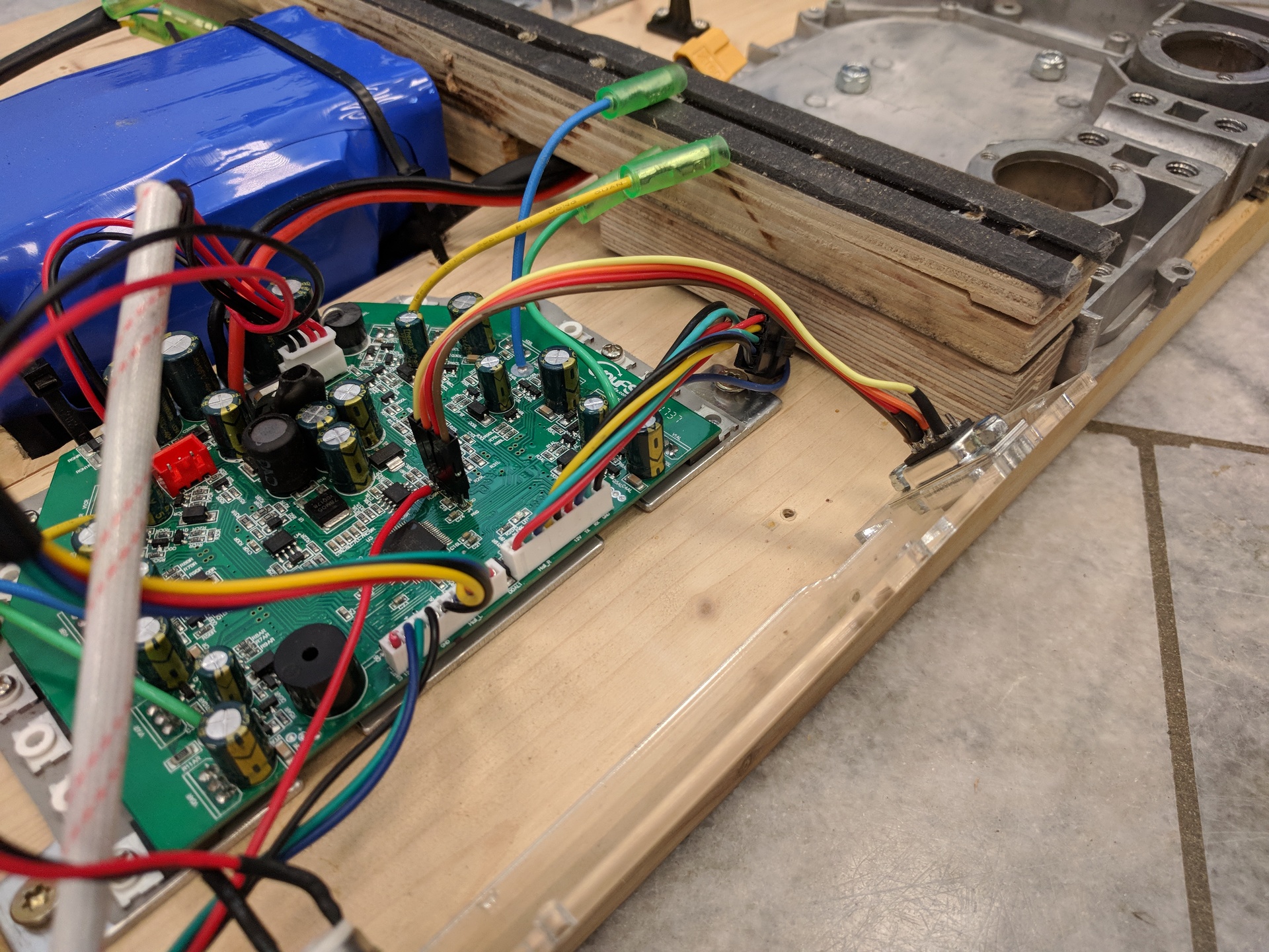
The electronics as well as the battery should be protected from mechanical impact and stress. To prevent mechanical stress, protruding components (transistors/capacitors) can be reinforced with hot snot aka. hot-glue adhesive.
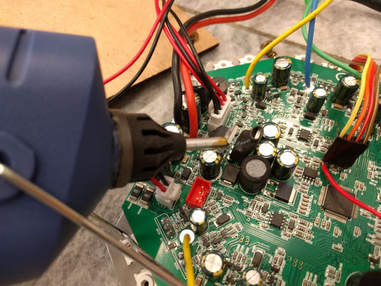
The whole PCB/battery assembly should be covered to prevent damage from debris and dirt.
If you want to use the mainbaord from your hoverboard, disconnect all cables from the printed circuit board and unscrew it. However, it is highly recommended to buy a new replacement board from eg. ebay for $20, because espacially with used hoverboards you can't be sure if they still work.
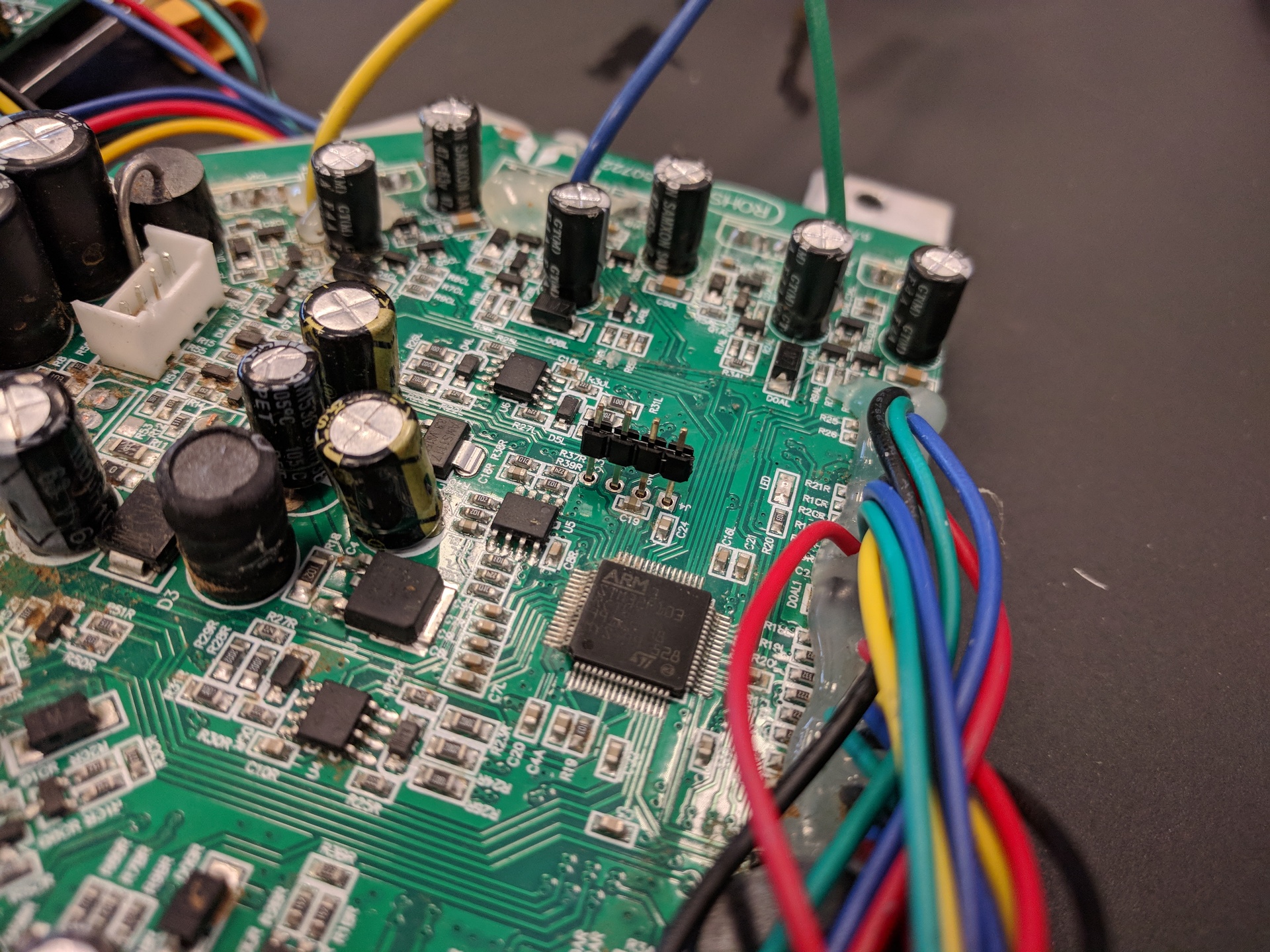
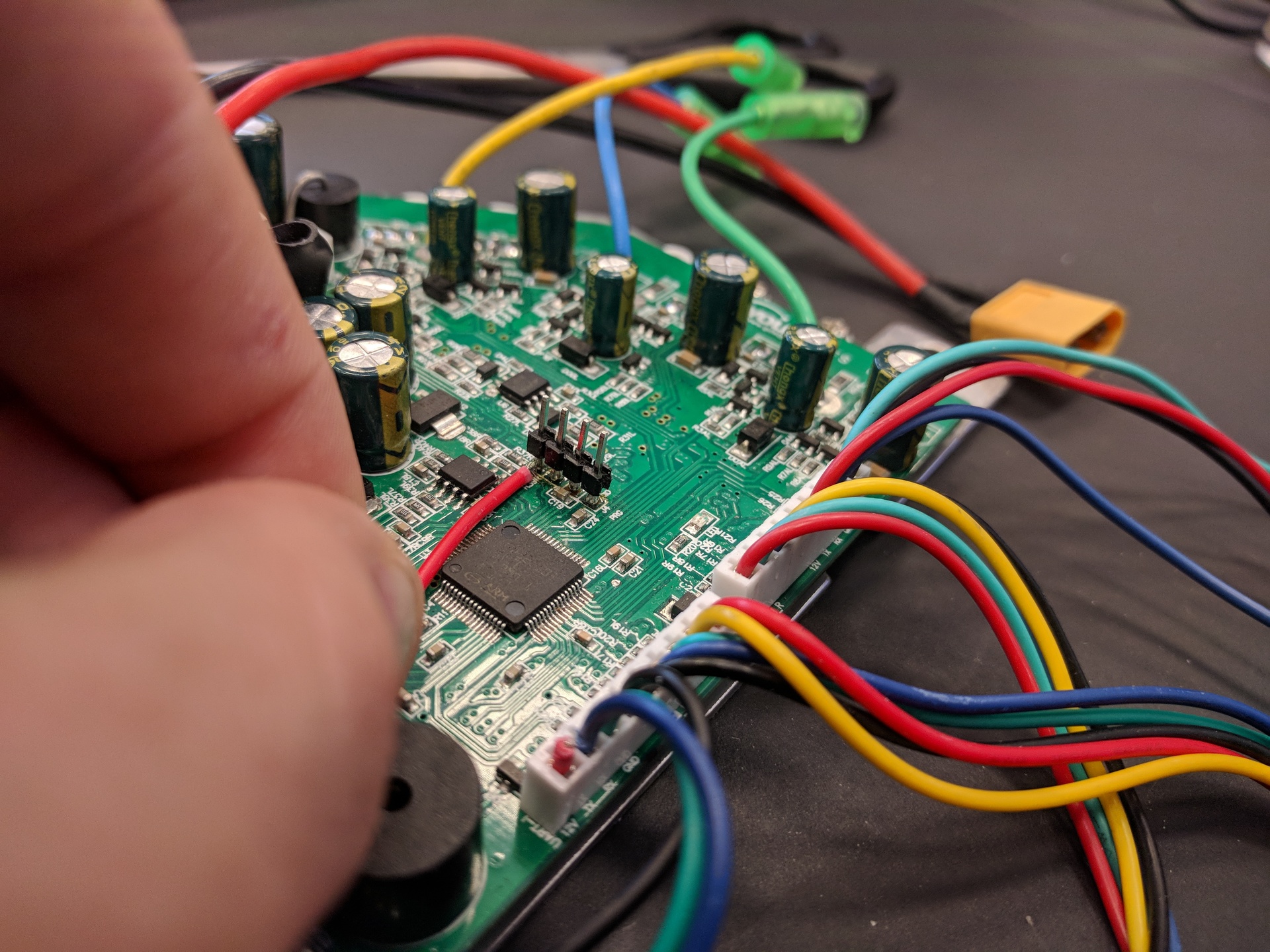
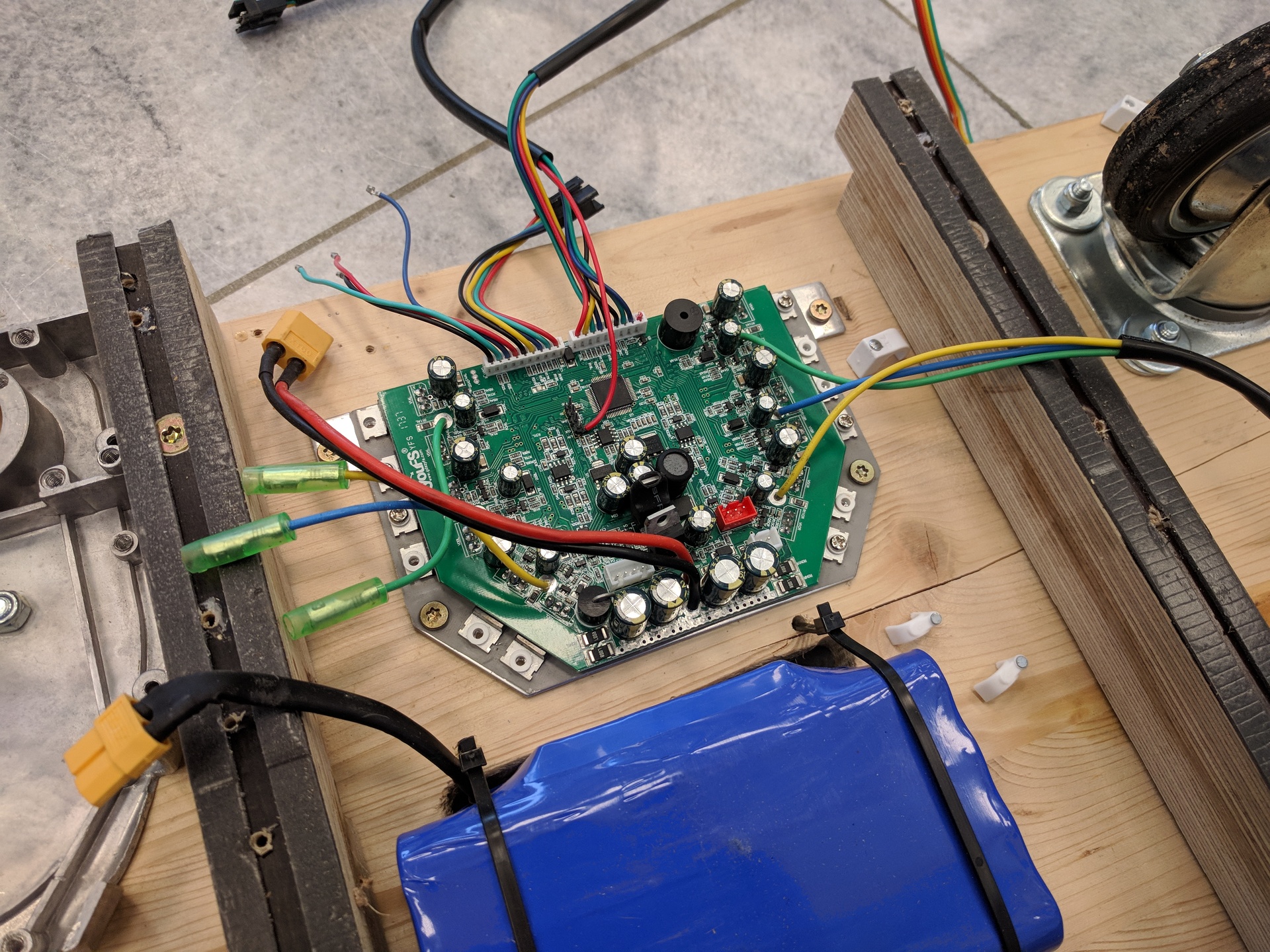
Independently of how you got your mainboard, you need to flash a custom firmware onto the board. You need to make the programming interface accessable. The easiest way to do this is to solder a pin header onto the pads on the mainboard
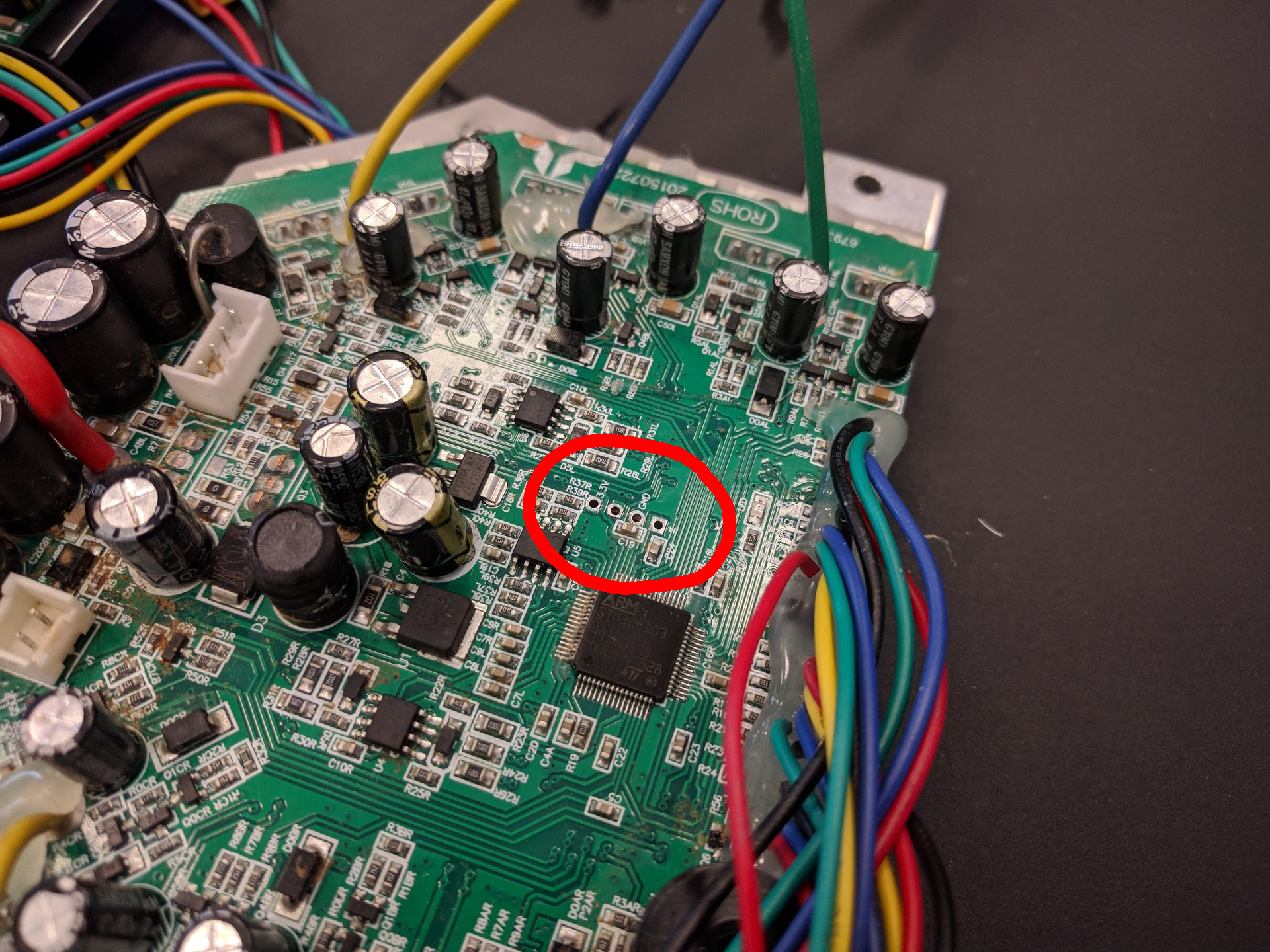
On most mainboards, you can't access the back of the pcb without removing the aluminium heatsink. This makes it a bit tricky to solder in the pin headers. One way that works for us is to insert the pinheader upside down, and sodering it in from the top of the baord. After you soldered all four pins, you can gently push down the plastic of the pinheader to leave more space for the jumper wires.
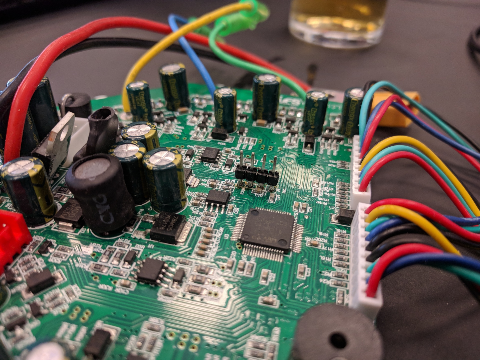
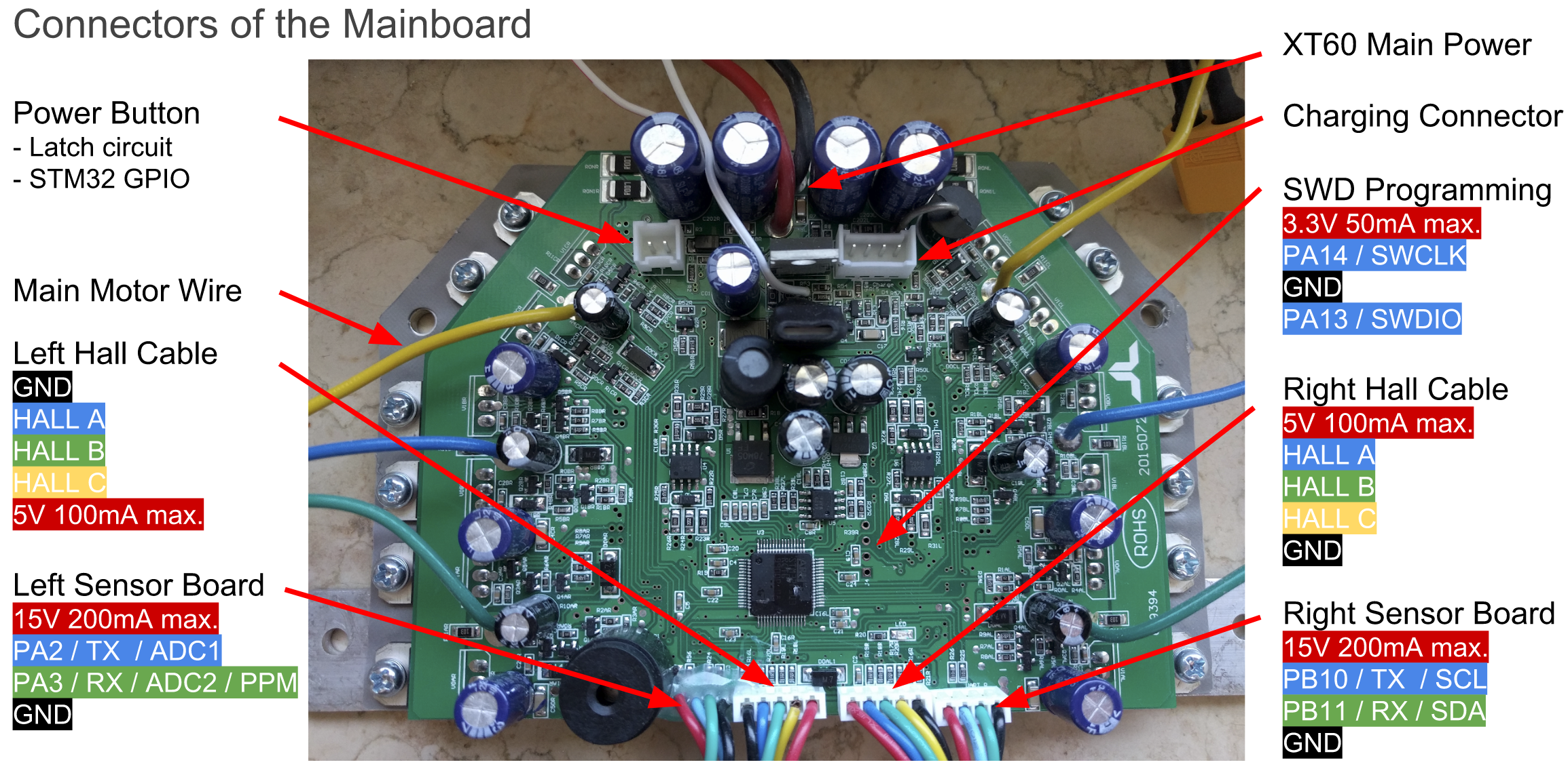
The ADC input range of the mainboard is 0V - 3.3V, so we need to power the gametrak hardware from 3.3V. Unfortuantly this voltage is not available on any of the sensor wires by default. To change this, we need to cut the 15V (red) cable of the left sensor wire (the longest connector with 4 wires) and connect it to 3.3V, which can be accessed from the programming header.
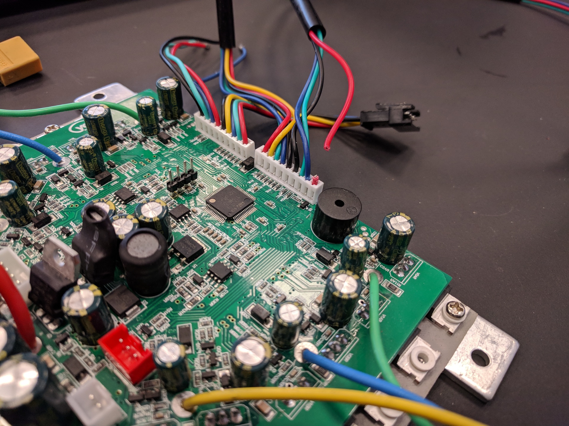
Next step is to connect the gametrak to the mainboard. For this, remove the connector of the left sensor wire (the longest connector with 4 wires) and tin the tips of the four wires with a soldering iron.
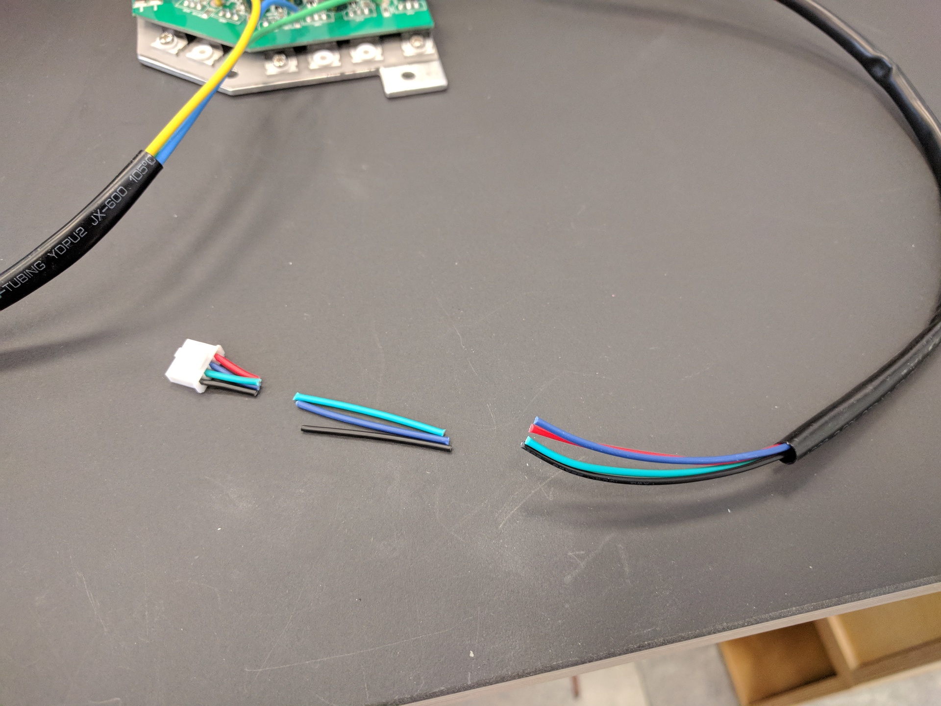
Then separate the individual wires of the flat cable coming from the gametrak, and remove the red wire. Connect the remaining four wires to the four wires of the mainbaord according to this picture:
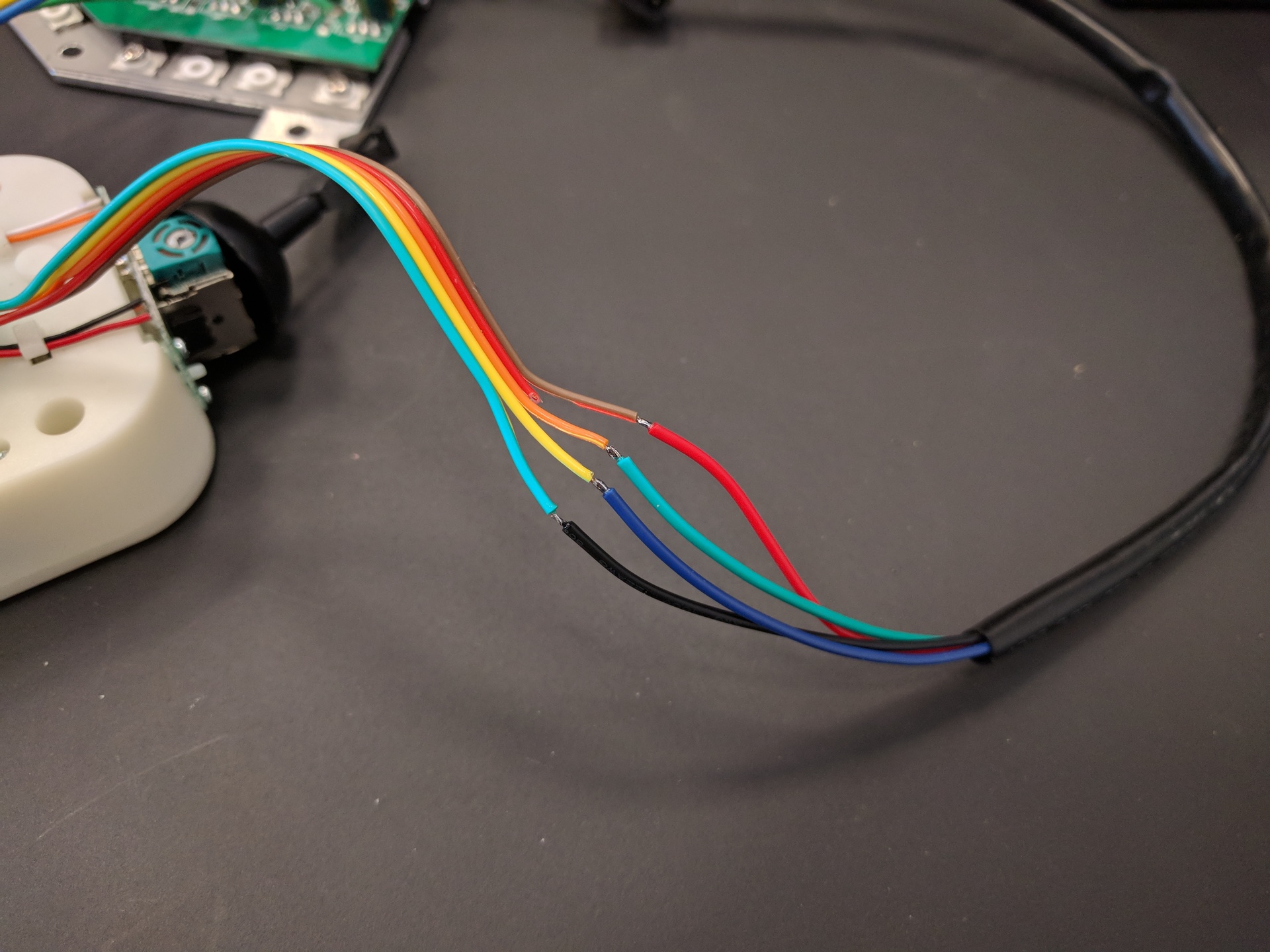
Make sure to isolate these solder connection with heatshrink tube, electrical tape or hot glue so they don't touch each otter.
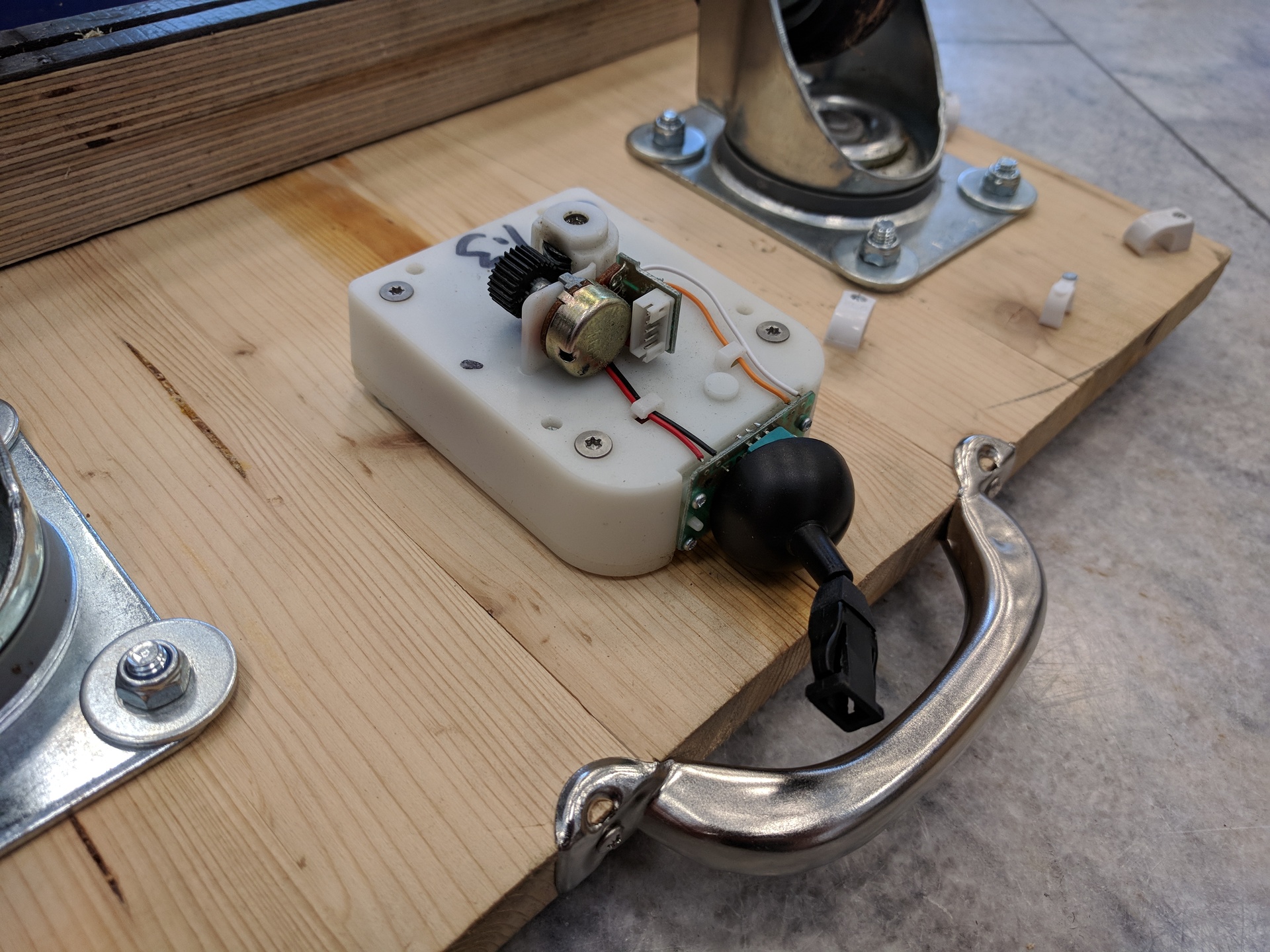
Disconnect the cable you just made from the gametrak pcb. This makes it easier to mount the gametrak on the wooden baseplate.
Just use the four holes in the gametrak to screw it to the wood. Don't tigthen them too strong or the gametrak will break eventually. Also, use some washers between the gametrak and the wood as spacers so the axis of the gametrak can rotate freely.
TranspOtter is powered from a LiIon hoverbard battery and charged from its charger.
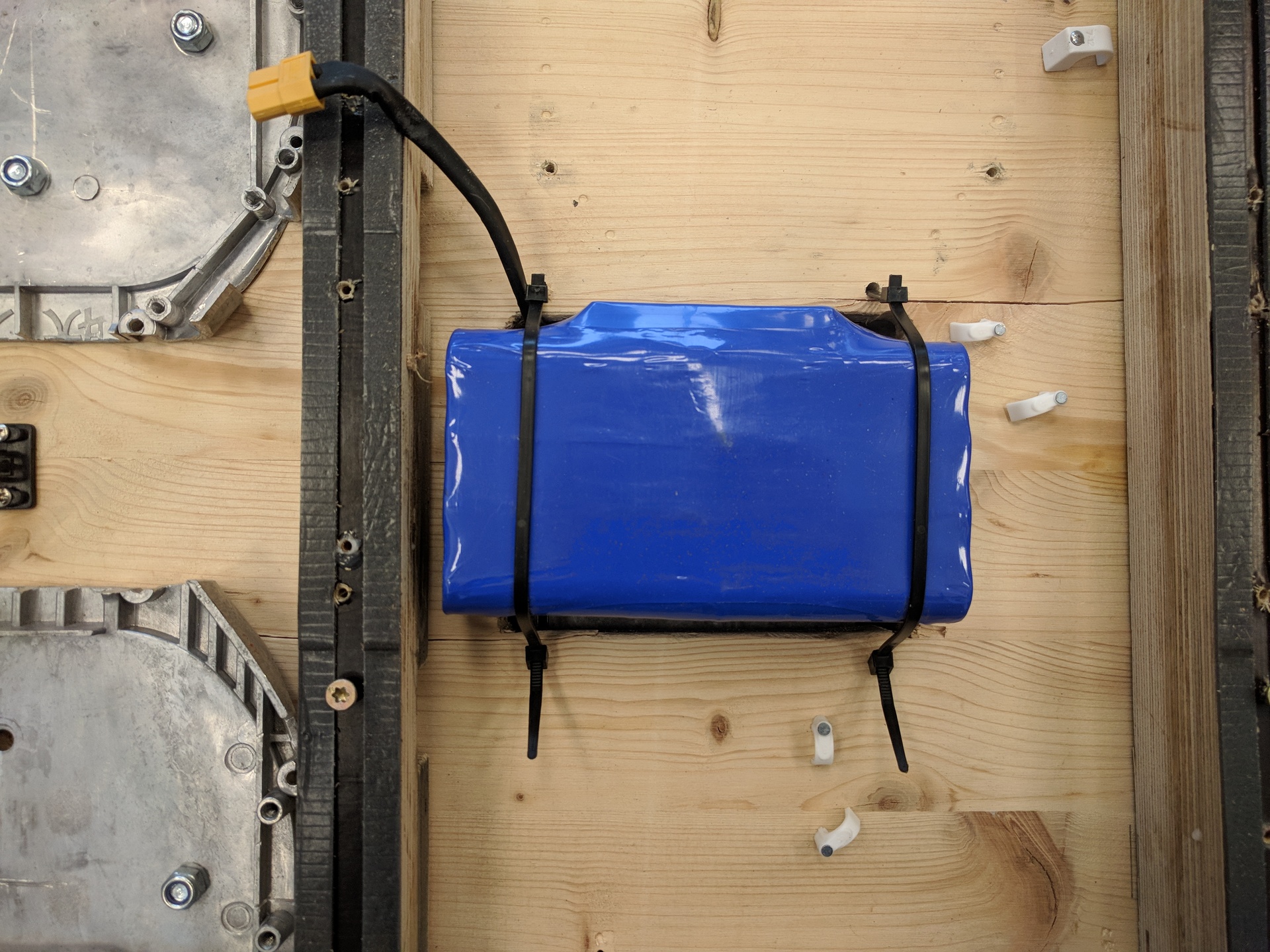
The battery is placed into the fitting battery cutout in the base and fixed in place with cable ties. It should sit loose/shock reistand to prevent it from getting damaged.
The original charging port adapter can be connected to the mainboard later, this allows you to charge your transpOtter with the original charger. This will also be covered in the assembly section later.
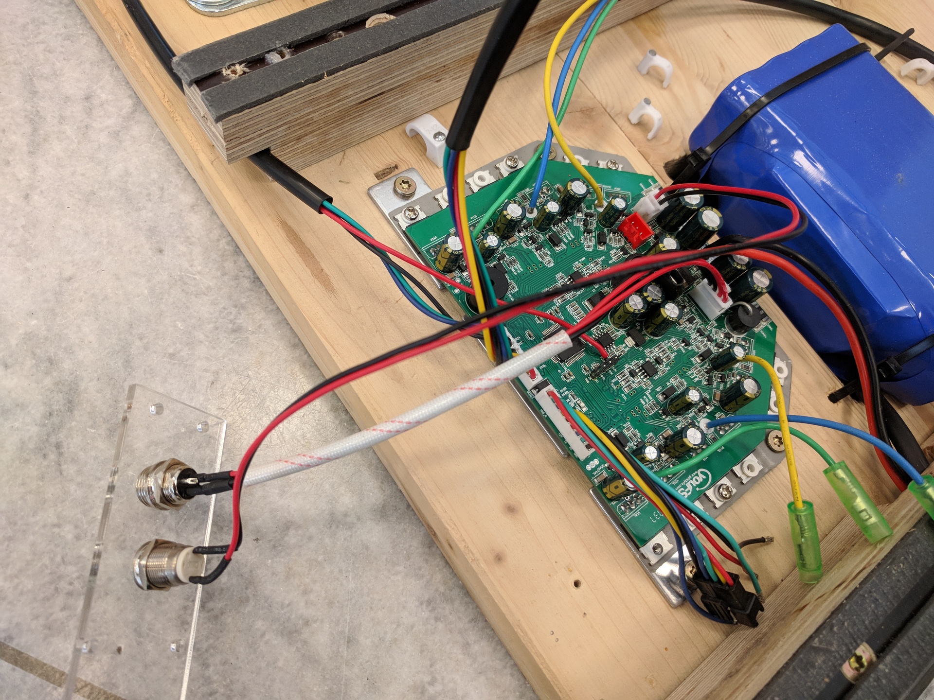
If you want to be able to disconnect the battery from the electronics (eg. for safety reasons or long-term storage) you can place the actual XT60 connection outside of the enclosure:
Use four screws to fix the mainboard to the baseplate.
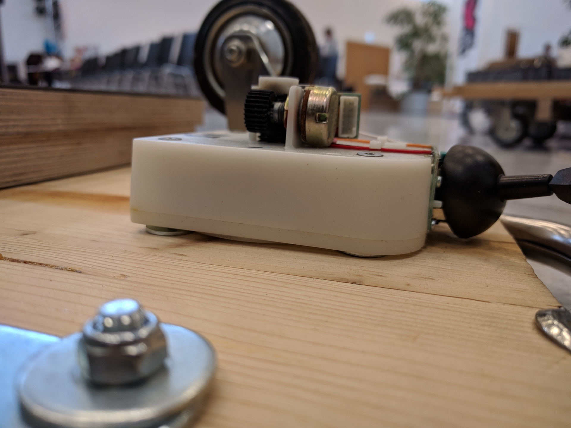
Next, connect the cable with the gametrak connector to the gametrak and fix it to the baseplate (eg. with hot glue, strippers...)
Connect the power button and the charging jack to the to the corresponding connectors on the mainboard, and mount them so some kind of frontplate (or glue them in place).
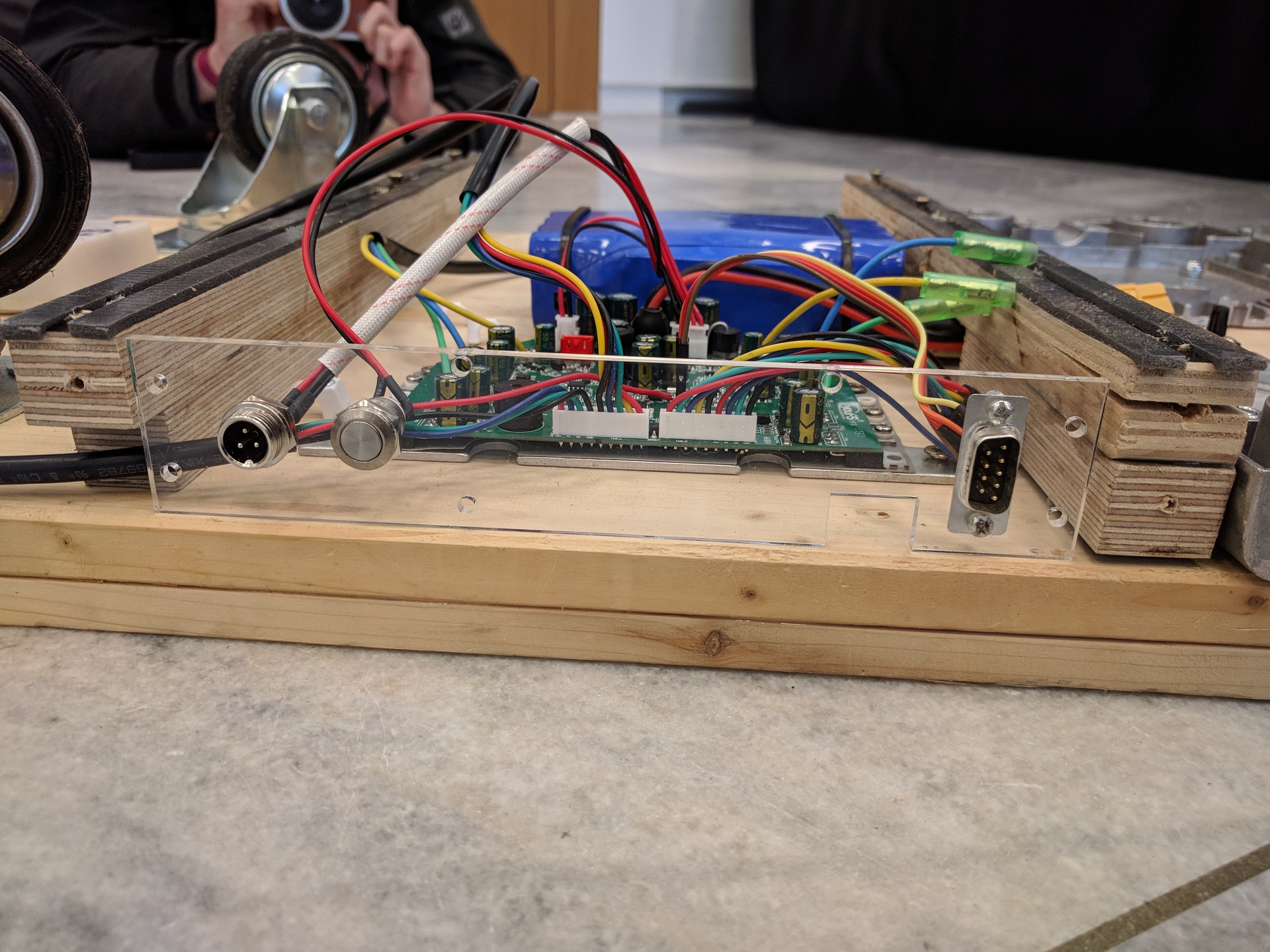
If you plan to enclosure the electronics, you can add an programming connector that is accessible from the outside of your transpOtter. This makes updating the firmware way easier. What you use is up to you, we decided to use a SUB-9 connector for this.
First make sure that you've installed the complete toolchain as described in 2.4
- Open the Ubuntu App (Start Menu -> Ubuntu)
- Navigate to the downloaded/cloned folder (either you've cloned the repo or downloaded and unpacked the .zip). For example if the folder is located on your Desktop enter the following into the ubuntu shell:
cd /mnt/c/Users/[Your Windows Username goes here]/Desktop/hoverboard-firmware-hack/and after that:make - Now plenty of text should show up in the shell and after the compiling finished you should find a
hover.binin thebuild/folder. If so you can continue with flashing it to the board.
Just make it.
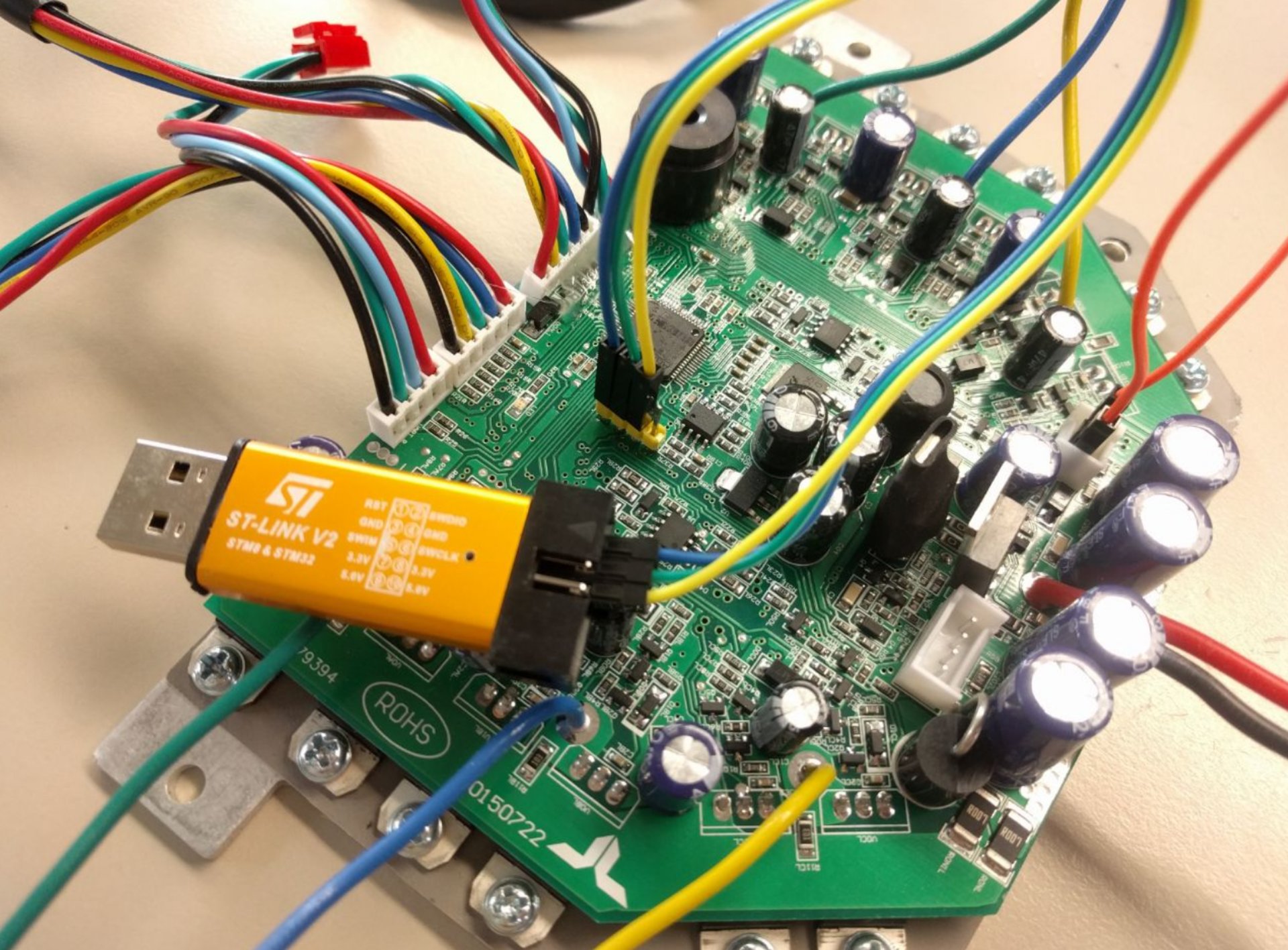
Connect a battery to the mainboard and the ST-Link programmer to the programming header on the hoverboard mainboard. Also make sure that you have the power button connected to the mainboard.

After installing the ST-Link Utility as described in chapter 2.4, you can now use it to flash the firmware.
- Start the ST-Link Utility and open the
hover.binfirmware binary that is located in thebuild/folder after compiling it (See 6.2). - Connect the programmer/ST-Link to the mainboard (assuming that you've already soldered the pinheaders to it, see 4.2). From ST-Link to the mainboard connect:
GND --> GND
SWDIO --> DIO
SWDCLK --> CLK
 If the pins aren't described via a silkscreen print on the PCB see the pinout reference here (Pinout description on the upper right "SWD Programming"):
- When the programmer is connected properly, hold down the power button of the hoverboard and keep it held. Now click on the "Target --> Program & verify" button in the ST-Link Utility.
- On the resulting pop-up click the "Start" button (while still holding the power button down!)
- When the mainboard beeps it's flashed and ready to be used.
- Connect the programmer to the mainboard like described in the Windows instructions above (point 2)
- If you never flashed your mainboard before, it needs unlocking. This can be done with the following command in bash:
openocd -f interface/stlink-v2.cfg -f target/stm32f1x.cfg -c init -c "reset halt" -c "stm32f1x unlock 0" - After building the firmware, hold down the power button and run the following command inside the hoverboard-firmware-hack folder:
st-flash --reset write build/hover.bin 0x8000000
If you need mor information about the flashing process in Linux, see the GitHub repository for more details.