
Our Walrus sensor, like this Walrus pup, is equally at home on land or in the water. Photo by Max Smith
The Walrus is an open-source sensor that measures temperature and pressure. It may be used in the air as a barometer or underwater as part of a system -- combined with barometric compensation -- to obtain changes in water level.
 Hard-mount variant of the Walrus. Major components are labeled. The pads to attach the watertight plug for the cable (i.e. the "HardMount"), on left, are currently unpopulated. These may be used for this kind of connector, or may have wires soldered directly to them before being embedded in an epoxy or other potting (i.e., waterproofing and encapsulating) compound.
Dimensions: 42.0 x 12.7 cm
ADD MASS once I get access to a lab balance again <<
Power
- Input Voltage: 3.3 to 5.5 V DC
- Logic Voltage: 0 to Vcc (Will operate at same logic level as input power supply)
Sensors
- Temperature: -40 to +85 C
- Pressure, typical: 0 to 2 atm (i.e. barometer to 10 m water depth)
- Pressure, maximum, untested: 0 to 30 atm (i.e. barometer to 290 m water depth)
- Cable length: 3 m (I2C) or 1000 m (RS-485).
The pressure operating range depends on the sensor element used. The MS5803-02BA is the standard model that we use for pressure measurements of up to 10 m
The pressure transducer contains an internal temperature sensor, and a secondary (and more accurate) external temperature sensor is also mounted on the Walrus. This external sensor is the MCP9808 in an 8-MSOP package. This sensor has a range of -40 to 125 C.
RS-485 communications allow for a signal to be transmitted over long distances, but require a device that can decode this signal, such as our Project-Longbow.
Pressure: +/- 1 mm water (0.1 mbar) Temperature sensor within pressure transducer (typical): +/- 2.0 C External temperature sensor (typical): +/- 0.5 C
The Walrus comes in two forms:
- Large form factor, through-hole mount: This is the legacy board with support for I2C and full-duplex RS-485 communication
- Smaller form factor, solder pads for wires or a waterproof plug: This current version makes better use of board space and utilizes a half-duplex RS-485 bus in addition to an I2C bus.
The files for production are located in folders starting with the word "Hardware". These folders contain:
- "*.brd" and "*.sch" files. These are the circuit board and its schematic for use with the EAGLE CAD software, which you can download for free: https://www.autodesk.com/products/eagle/free-download
- A "*.csv" file that contains the "BoM" -- the bill of materials. This lists all required parts to construct the board
- A ZIP archive containing a set of "Gerber" files. These are the files that machines use to create a circuit board and a stencil to help you to apply solder paste (see below)
- 2-layer copper
- Minimum trace width: 0.2 mm
- Single-sided
- Surface mount components
All Walrus boards are single-sided and use only surface-mount components for rapid fabrication using standard equipment.
We strongly recommend that circuit boards be printed by a reputible manufacturer. Many such industries exist in China, India, and developing or developed countries.
Before you can start to populate the circuit board, meaning adding components to it, you will need solder paste and a stencil. If you have access to a laser cutter, you can create your own stencil (https://learn.adafruit.com/smt-manufacturing/laser-cut-stencils). If you do not, the company that prints the circuit boards should be able to provide one. If all else fails, you can try to cut out a stencil with a small knife, or use a solder-paste syringe, though both of these methods can lead to difficulties (such as bridged connections). Additional information on how to stencil can be found here: https://www.sparkfun.com/tutorials/58.
To help you in using the stencil, we provide STL files for 3D-printable plates in each of the hardware directories. These plates hold the board in place and provide a level surface on which to use the stencil.
ADD PLATE FOR HARDMOUNT <<
After this, you can use a tweezers and steady hands, or a pick-and-place machine, to gently place each component over the right pads, and in the right orientation. Do not worry if they are slightly misaligned; the surface tension of the solderi, once it is melted, will help to rotate the components into place.
"Reflowing" is the process of heating solder until it flows and attaches to components. A basic introduction is here: https://learn.sparkfun.com/tutorials/electronics-assembly/reflow
There are four major ways to reflow:
- Using a professional oven (see link above)
- With a customized toaster oven: See https://www.sparkfun.com/tutorials/60, and a basic internet search will show you many, many other ideas
- You can also use a simple electrical skillet -- the kind that you might use to make some food. https://www.sparkfun.com/tutorials/59
- Using a hot-air rework station; this is a bit time-intensive, but lets you control the heat, and I often use it for small boards. https://learn.sparkfun.com/tutorials/how-to-use-a-hot-air-rework-station/all
After reflowing, you may need to clean up jumped connections using solder wick.
After reflow is complete, check if everything worked. Do you have any jumped connections? Any remaining solder paste that hasn't been reflowed? This can be the trickiest part, and one for which access to a multimeter is essential. An oscilloscope and a digital logical analyzer can help too. Debugging electronic circuit boards is a process that requires significant skill and practice, so be sure that you can work with someone with some expertise. I would suggest an electrical engineering student or professor at a local university.
"Pin" is the name of the pin as labeled on the board. "Wire" is the color of the Alpha Wire 5004C cable that we use; you may use something different based on what manufacturers exist where you are; that's okay, just record the color convention! (We sometimes use another cable in which we use a white wire for SDA and a green wire for SCL, but have found that Alpha Wire brand works best.)
Add image of cable ends (optional) and find how to integrate with housing section; cabling is a distinct topic, but the step of attaching the cable lies within the housing-construction step <<
Here we assume that you are using standard Alpha Wire cables with waterproof attachments, available in 3-meter and 1-meter lengths; the 3-meter length is our standard because this is the longest that it can be and still communicate reliably via I2C. Because of the wire insulation colors available for these cables and the locations of their attachment points to the 4-pin "HardMount" plug (3D model), our HardMount devices do NOT match standard wire-color definitions (or any kind of standard). Wire-color definitions are:
| Color | Connection |
|---|---|
| Brown | V+ (3.3-5.5 V) |
| White | GND |
| Black | SIG1: SDA or RS-485 A |
| Blue | SIG2: SCL or RS-485 B |
These are our more standard wire-color suggestions
| Color | Connection |
|---|---|
| Red | V+ (3.3-5.5 V) |
| Black | GND |
| Brown | SIG1: SDA or RS-485 A (RX+, TX+) |
| Orange | SIG2: SCL or RS-485 B (RX-, TX-) |
If you attach your own wire, pins on the Walrus are as follows, looking at the top side with the screw hole away from you:
- Top left: SIG1: SDA for I2C; A (+) for RS-485
- Top right: SIG 2: SCL for I2C; B (-) for RS-485
- Bottom left: VCC (3.3V to 5.5V)
- Bottom right: GND

Go to https://www.arduino.cc/en/main/software. Choose the proper IDE version for your computer. For Windows, we suggest the non-app version to have more control over Arduino; this might change in the future. You will have to add custom libraries, so the web version will not work (at least, as of the time of writing). Download and install the Arduino IDE. Open it to begin the next steps.
To install firmware on the Walrus, you use the 2x3-pin ICSP (also called ISP) header with a special device called an "in-circuit system programmer" (or just "in-system programmer; yup, that's what the acronym stands for).
Many devices exist to upload firmware, including:
- The official AVR ISP mkII (no longer produced but available used)
- Using an Arduino as an ISP
- The versatile Olimex AVR-ISP-MK2
- The Adafruit USBtinyISP
Note: Be sure to download and/or update drivers for your ISP.
Using an AVR ISP, upload the proper firmware programs from the "Firmware" directory in this repository using the Arduino software:
- Large form factor PTH board
- I2C mode: No firmware required, but fuses must be set (see instructions, below)
- RS-485 mode: Longbow_2BA_0x6B (This firmware is for the 02BA; you will need to switch these with other coefficients, available in the commented and uncommented lines of /Firmware/Walrus_I2C_5BA, to modify this for a different transducer pressure range.)
- Small form factor hard-mount board
- I2C mode: Set the fuses (see instructions below) and then upload Walrus_I2C_5BA (This firmware is for the 05BA; there are lines in this code to comment and uncomment to modify it for other versions of the Walrus.)
- RS-485 mode: Longbow_2BA_0x6B_HalfDuplex (This firmware is for the 02BA; you will need to switch these with other coefficients, available in the commented and uncommented lines of /Firmware/Walrus_I2C_5BA, to modify this for a different transducer pressure range.)
@bschulz1701: could you provide a link to the repo (is it TPDH lib) for " * I2C mode: No firmware required. Library communicates directly with sensors via their built-in I2C addresses."
Instructions:
- Open the Arduino IDE.
- Follow these instructions to install the ATTinyCore board definitions
- Select ATTiny1634 (No bootloader)
- Plug your ISP of choice into your computer (via a USB cable) and onto the 6-pin header. There are two ways to place it on; the header is aligned such that the ribbon cable should be facing away from the board while programming. If this fails without being able to upload, try flipping the header around. This should both power the board and provide communications.
- Go to Tools --> Programmer and select the appropriate programmer based on what you are using.
- Go to Tools --> Burn Bootloader. Yes, we know that you just selected "ATTiny1634 (No bootloader)", but this step sets the fuses, which configure their internal oscillator and brown-out detection.
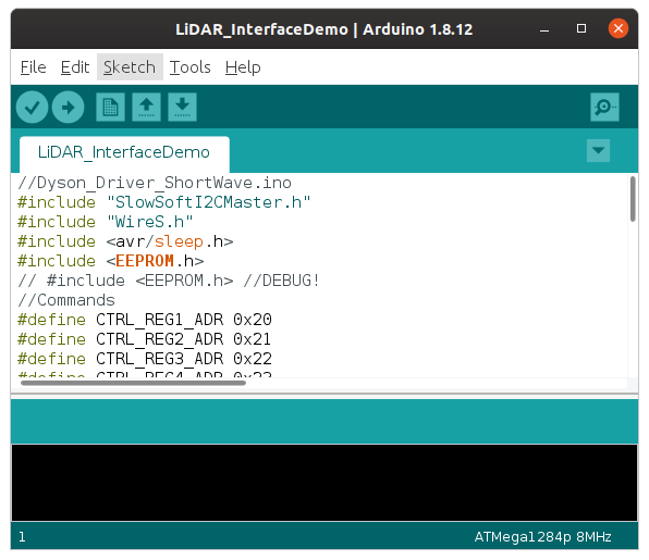
- Unless you are configuring a large-form-factor Walrus in I2C mode (in which case you are now done), open the appropriate firmware (linked above). Then go to Sketch --> Upload Using Programmer. After several seconds, you learn whether you succeeded or failed. Hopefully it worked!
Uploading using the in-system programmer.
Important note for Linux users: You must supply permissions to the Arduino IDE for it to be able to use the ICSP, or you will have to run it using sudo. The former option is better; the latter is easier in the moment.

Walrus v0.0.0 PTH and its housing. Left: 3D-printed top of the housing; the slits are to prevent large material from hitting the sensor. Center: the bottom of the housing. Self-tapping holes are to screw the board onto this housing. The cable entering the housing through a tightly-fitting hole on the "south" side of the image has not yet been stripped to expose the ends of the individual wires. A different variant of the housing is longer to allow the user to strip more of the cable if desired while maintaining the cable jacketing in contact with the hole. Top right: Walrus v0.0.0. This fully-functional initial version is significantly larger than the current unit. Note the pressure transducer (white circle) at top left, and the fact that this has pins and hardware for a full-duplex RS-485 connection. Bottom right: U.S. penny for scale; 19.05 mm (0.75 inch) diameter.
 Render of the enclosure design. The epoxy encapsulation tray sits within a wider cylinder containing a screen designed to keep sediment out. Design still in progress (19 June 2020).
- 3D printer filament: ABS suggested
- Two-part epoxy: 3M DP270 Clear; can be purchased from McMaster-Carr
- Conformal coating to help protect components during epoxy encapsulation. We suggest MG 419D (Digi-Key purchase link). If you prefer a silicone conformal coat, we suggest MG 422C, though we recommend this instead for an external (rather than internal, as this will be), flexible coat.
- 4-pin "HardMount" plug (3D model)
- HardMount cable: Alpha Wire AR0400105-SL357 (-40 PVC jacket)
- [Alpha Wire page](http://www.Alpha Wire.com/en/Products/Connectivity/AlphaConnect/Cordsets/AR0400105)
- Example from DigiKey
- Comes in a [variety of lengths from 0.6 to 20 meters](http://www.Alpha Wire.com/en/Products/Connectivity/AlphaConnect/Cordsets/AR0400105) (Digi-Key search results)
- User may choose a cable that terminates in a plug, alongside a matching recepticle in the wall of the data-logger box, for a specialized solution that does not require cable glands.
- One #2-56 x 3/16" thread-cutting screw per board to fasten it to the housing for the epoxy encapsulation
- 7x #4-24 self-tapping screws (Additional link: untested but probably identical screw from Fastenal)
- 3x to hold board in place
- 4x to to attach the lid of the 3D-printed enclosure
Assuming that we are using a 4-wire connection instead of the full-bridge RS-485 (supported by the large-form-factor/PTH board) because this is being phased out in favor of a 4-wire half-bridge.
- 4-conductor Alpha Wire, soldered to pads or rings
Subfolders of the "3Dprint" directory contain "STL" files that you can use with a program called "Slic3r" to create 3-D printable parts for your housing. Assuming that you have a Prusa 3D printer, you will want to download the Prusa variant of Slic3r. This comes with the appropriate setup files and information to help you configure the printer and print your parts.
Link to all housings once designed <<
TO DO: Options for HardMount with (and perhaps without) the plug. <<
Solder the HardMount plug onto the four SMD pads with the notch (for plug orientation) at the bottom side of the board. The best way to do this is to:
- Add small pillows of solder to each of the four pads, enough to create contact with the HardMount solder cups but not so much that it is not possible to slide the HardMount plug over them.
- Slide the HardMount plug on; it will take a bit of finesse to keep it from being pushed off of the solder pillows.
- Using some Blu Tack (or equivalent), fix the board and HardMount plug in place
- Double-check that the notch in the HardMount plug is on the back side of the board
- Solder on the first connection
- Check whether the board is straight; reflow the solder as needed until the connection is secure
- Solder the second connection
- Flip the board, ensuring that it is straight (if not, make changes)
- Solder the other two solder-cup connections
Optionally, pass the cable through its hole in the 3D-printed enclosure bottom for the pour-over epoxy encapsulation. This means that you will not later need to pass the full length of the cable through the hole!
Next, solder the cable through the rings or onto the SMD pads. Ensure that all connections are solid prior to encapsulation. The encapsulation process will strain-relieve the cable.
@bschulz1701: with this epoxy, do we need to conformally coat the boards first?
After creating the housing, affix the logger to it using the #4-24 screws listed above. If the design includes an integrated cable (instead of a HardMount plug), MAKE SURE that a cable of the desired length is attached beforehand! Otherwise, MAKE SURE that a HardMount plug is attached beforehand!
@superchap123: Your clip design would come in here too.
Before applying the epoxy, make sure that all zones where epoxy could leak out of the 3D-printed lower portion of the enclosure are sealed. The epoxy is somewhat viscous, so gaps need not be made completely airtight.
Next, pot the boards in 2-part epoxy (per the supplies list above, we suggest 3M DP270 Clear; can be purchased from McMaster-Carr). Be careful to fully cover everything except for the white inside membrane on the pressure transducer. If epoxy touches this, it is rendered unreliable or useless.
Walk through assembly with images <<
 Potting the large-form-factor Walrus. 3D print designs for this lower/tray portion and the to-be-attached lid are included within this repository in the "3Dprint" folder.
These instructions assume that you are using a Margay or Okapi data logger. If this is not the case, similar pins are available on a generic Arduino board.
Pass the cable through the housing to the logger, ideally using a cable gland that you can tighten on the box containing the logger: this can provide waterproofing as well as some strain relief. Follow the table in the Wiring and pinout section to attach individual wires to the appropriate pins on the data logger and (if needed) RS-485 converter. In bulleted-list form, with colors given for Alpha Wire 5004C:
- V- (Walrus) to GND or V- (Logger)
- V+ (Walrus) to a positive voltage source between 3.3 and 5.5 V (Logger)
If using the sensor in I2C mode, attach the signal wires as follows:
- SIG1 (Walrus) to SDA (Logger)
- SIG2 (Walrus) to SCL (Logger)
If using the sensor in RS-485 mode, attach the signal wires to the Longbow Backpack as follows:
- SIG1 (Walrus) to A+ (Longbow)
- SIG2 (Walrus) to B- (Longbow) (You may use another RS-485 converter, in which case the wiring is up to you!)
Then use another set of four wires to connect the Longbow to the logger:
- GND to GND
- Vin to a 3.3 to 5.5 V power source
- SDA to SDA
- SCL to SCL We recommend Pololu's pre-crimped wires for this with a male terminal, as it ensures that you can have these four wires in the proper order for both the Walrus and the data logger. For this reason, Northern Widget data loggers (Margay and Okapi) always have these four pins in the order:
- GND
- V+
- SDA
- SCL
After uploading the Walrus firmware, you should be able to use any standard Arduino device to connect to it and read its data.
The firmware uploaded to the Arduino device should include the Walrus library as demonstrated below. Documentation for the Walrus library, auto-generated using doxygen, is available on its linked GitHub page.
This code is intended for any generic Arduino system.
Note: Not all of this code is built yet. THIS IS A TEMPLATE!
// Include the Walrus library
#include "Walrus_I2C.h"

// Declare variables -- just as strings
String header;
String data;

// Instantiate class
Walrus myWalrus;

void setup(){
    // Begin Serial connection to computer at 38400 baud
    Serial.begin(38400);
    // Obtain the header just once
    header = myWalrus.getHeader();
    // Print the header to the serial monitor
    Serial.println(header);
}

void loop(){
    // Take one reading every (10 + time to take reading) seconds
    data = myWalrus.getString();
    // and print it to the screen
    Serial.println(data);
    delay(10000); // Wait 10 seconds before the next reading, inefficiently
}Not yet developed.
The Margay data logger is the lightweight and low-power open-source data-logging option from Northern Widget. It saves data to a local SD card and includes on-board status measurements and a low-drift real-time clock. We have written a library to interface with the Margay, which can in turn be used to link the Margay with sensors.
// Include the Walrus library
#include "Margay.h"
#include "Walrus_I2C.h"

// Declare variables -- just as strings
String header;
String data;

// Instantiate classes
Walrus myWalrus;
Margay Logger; // Margay v2.2; UPDATE CODE TO INDICATE THIS

// Empty header to start; will include sensor labels and information
String Header = "";

// I2CVals for Walrus
uint8_t I2CVals[] = {0x4D}; // DEFAULT

//Number of seconds between readings
uint32_t updateRate = 60;

void setup(){
    Header = Header + myWalrus.getHeader();
    Logger.begin(I2CVals, sizeof(I2CVals), Header);
    initialize();
}

void loop(){
    initialize();
    Logger.run(update, updateRate);
}

String update() {
    initialize();
    return myWalrus.getString();
}

void initialize(){
    myWalrus.begin();
}Not yet developed.
Pre-deployment check:
- Ensure that the cable is appropriately strain relieved on the logger end (the screw plug or epoxy, depending on model, handles this on the sensor end).
- Check cable for nicks or tears; replace if needed.
- Ensure that the unit functions properly and gives good readings in the lab
- Check that you have programmed the desired reading duration
- Ensure that the transducer for your Walrus functions over the desired pressure range
Once you are ready, you can deploy your sensor in the river, lake, or atmosphere that you hope to measure. Remember that you must correct all pressure measuremennts for barometric pressure in order to recover a water level. If the water is saline or heavily sediment laden, you must know the salinity or sediment-adjusted density as well.
Support for this project provided by:


This work is licensed under a Creative Commons Attribution-ShareAlike 4.0 International License.