Unfortunately IP camera manufacturers aren't yet shipping hardware with OpenIPC preinstalled, so to install OpenIPC onto a camera which is still using factory firmware images, one of the following methods must be used:
-
The Coupler project makes available firmware images which can be installed using the firmware upgrade mechanisms which are built into the factory firmware of many cameras.
-
Flashing the OpenIPC firmware using the U Boot bootloader which is included in the vendor firmware. This method interrupts the normal boot process of the vendor firmware, and instead instructs U-Boot to load the OpenIPC firmware over the network, and write it to the flash storage (replacing the main portion of the vendor firmware). This method requires the camera's case to be opened to connect a UART adapter to the camera's internal "console" serial/debug port.
Instructions for using Coupler can be found in the project's documentation.
The SoC includes the CPU core of the camera, as well as all the necessary peripherals such as the camera and network interfaces. For various reasons (including the limited onboard storage space on most IP Cameras), the OpenIPC project currently builds separate firmware binaries for each SoC model. You must identify the SoC which your camera uses, so that you can use the correct firmware binaries. This can be done by reading the markings on the SoC IC package on the camera's main PCB (see example photo below), or by using software such as ipctool to identify the SoC model from the vendor firmware.


Hisilicon Hi3518EV100, Ingenic T20, T31 and T40 SoCs marking. Relevant symbols highlighted with yellow.
TFTP stands for Trivial File Transfer Protocol. As the name implies, it is a very simple protocol intended for transferring files over a local computer network. TFTP does not support authentication. Its code is so tiny and simple that TFTP-clients are widely used in thin-clients and embedded systems for retrieving bootable images from a designated boot server on the local network.
...then it's easy. Pre-compiled and ready-to-use binary package for your distro most likely already exists in distro's repo, and you only need to install it and set it up.
sudo apt install tftpd-hpa
sudo sed -i '/^TFTP_OPTIONS/s/"$/ --create"/' /etc/default/tftpd-hpa
sudo systemctl restart tftpd-hpa.serviceNote: some users reported issues (connection timeouts) when using
tftpd-hpawith recent versions of Ubuntu. In that case, you can try with an alternative TFTP server.
In order to make a connection to UART port you will need a serial port adapter for your PC.

Before you connect that adapter to you camera, make sure that it's working voltage is set to 3.3 volt! Sometimes, you only need to flip a jumper to achieve that. But in some cases you might need to solder a wire, a zero Ohm resistor, or make a connection between two contacts with a blob of solder. Some adapters support only 5 volt. In that case, you will need an additional logic level converter connected between the adapter and UART port on your camera.
One of the contact pads you will need to connect you adapter to is GND (ground).
It is easy to discover using a multimeter in continuity mode. Put one of the
leads onto a well-known exposed ground pads. Usually, these are large open
copper contact areas around mounting screw holes, USB port housing, SD card slot
metallic walls. Use another lead to slightly touch control pads until you see or
hear a notification from your multimeter that the circuit is closed. That means,
you found the ground. Now, you need to find two more: RX and TX, both used
for receiving and transmitting data, respectively. Start with TX. It transmits
series of characters and quite easy to spot.
Be aware that you are looking for a contact with 3.3v potential between it and the ground. Test possible connection points with a multimeter and mark those showing 3.3 volt. This way you won't have to test everything, and you save yourself from hitting say a 12 volt connector intended for infrared LED array or whatnot.
Connect GND pin on your camera to GND pad of the adapter, connect USB
connector of the adapter to a USB port on your PC, start a terminal emulator
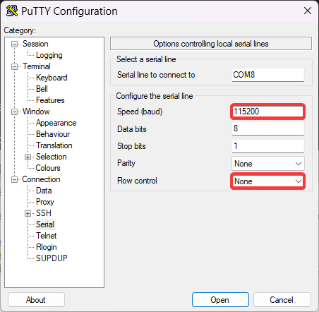
application and connect to your adapter. Set your terminal settings to
115200 bps baudrate, 8 bits, no parity, 1 stopbit, no flow control.
Here's a few command lines for various terminal programs with session logging. Pick your poison.
Start a sessions with
screen -L -Logfile ipcam-$(date +%s).log /dev/ttyUSB0 115200Use Ctrl-a followed by \ to exit the session.
Start a sessions with
minicom -b 115200 -8 --capturefile=ipcam-$(date +%s).log --color=on -D /dev/ttyUSB0Use Ctrl-a followed by x to exit the session.
Start a sessions with
picocom -b 115200 --databits 8 --parity n --stopbits 1 --flow n --logfile=ipcam-$(date +%s).log /dev/ttyUSB0Use Ctrl-a followed by Ctrl-x to exit the session.
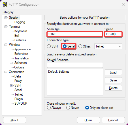
If you opt for a GUI terminal, namely PuTTY, this is how it should look like:
Then, connect RX pin on the adapter to a possible TX contact of UART port
on your camera. Power the camera with its standard power adapter. If you had a
lucky guess then you'll start seeing booting log in your terminal window. In
some cases, if you see garbled text on you screen instead of booting kernel,
you might need to change the connection speed to 57600 bps and try again.
If your screen remains blank, try another UART contact, and then another, until you hit the proper one.
After you found the TX pad, connect it to RX pin on your adapter. Yes, it is
a cross-connection. Whatever transmits goes into a receiver and vice-versa. Now,
put a heavy object -- a railroad nut, an antique tin solder, a shot of vodka
(full) -- on any letter key of your computer keyboard and start connect
remaining TX pin of your adapter to different pads on the camera until you see
it backfeeding to the terminal. As it happens, you have successfully completed
a UART connection to you camera. Now you may drink the vodka.
NB! Usually, there is a fourth contact on a UART connector marked VCC. It is
used for powering camera during initial programming by manufacturer. We strongly
advise not to power your camera though that pin, but use the OEM power connector
for this purpose.
Reboot the camera and try to interrupt its boot sequence in order to access
bootloader console by pressing a key combination on your computer keyboard,
between the time the bootloader starts and before Linux kernel kicks in.
Key combinations differ from vendor to vendor but, in most cases, it is
Ctrl-C, less commonly -- Enter, Esc, * or just any key. Carefully read text
appearing on screen while booting, you might see a hint there. Some cameras
require more exotic combinations not revealed in booting logs. You may try to
look them up on the internet, or ask on our Telegram channel.
Chances are, we have already dealt with such a camera and know the combo.
If you succeeded and got a command prompt then congrats, you've got access to your camera's bootloader.
From this point on, we strongly advise you to keep a record of everything you do. Enable session logging in your terminal. Even better, create a text file on your computer and write down all commands you run and how system responses to them.
Most IP cameras nowadays are equipped with 8 or 16 MB NOR or NAND flash memory. You can check the type and size of the chip installed on of your camera in the bootloader log output. You'll see something like this:
U-Boot 2010.06-svn (Oct 21 2016 - 11:21:29)

Check Flash Memory Controller v100 ... Found
SPI Nor(cs 0) ID: 0xс2 0x20 0x18
spi_general_qe_enable(294): Error: Disable Quad failed! reg: 0x2
Block:64KB Chip:16MB Name:"MX25L128XX"
SPI Nor total size: 16MB
Another example:
U-Boot 2013.07 (Feb 27 2019 - 02:05:08)

DRAM:  64 MiB
MMC:   msc: 0
SF: Detected EN25QH64
Which shows the flash memory model (EN25QH64) that you can look up online to
find a data sheet. Also, 64 in the model number hints for a 64 Megabits memory,
which is equivalent to 8MB. Similarly, 128 would be equivalent to 16MB.
You should also be able to identify the model of the flash memory by looking up at the board, but this is usually a difficult task because the chips are very small and may not come with clear markings.
After you get access to the bootloader console, run help to get a list of
available commands. Check if you have tftp among them. If you do, then saving
the original firmware should be a breeze. You only need to set up access to your
TFTP server from step 2.
NB! If your bootloader does not have tftp, you can still make a copy of the
original firmware. Read here for more.
Check the system environment using printenv command. Look for ipaddr,
netmask, gatewayip and serverip parameters. The first three set IP address,
netmask of your camera, and the IP address of the network gateway for accessing
local network. The fourth parameter is an IP address of your TFTP server. Assign
the values by setenv command (use IP addresses and netmask corresponding to
your local network), then save the new values into environment with saveenv
command.
setenv ipaddr 192.168.1.253
setenv netmask 255.255.255.0
setenv gatewayip 192.168.1.1
setenv serverip 192.168.1.254
saveenv
To dump the original firmware, you need to save the contents of camera's flash memory to a file. For that, you must first load the contents into RAM. Here's how you do that. Initialize the Flash memory. Clean a region of RAM large enough to fit whole content of flash memory chip. Read contents of the flash from into that region, then export it to a file on the TFTP server.
Please note, that flash type, size and starting address differ for different cameras! For exact commands please use automatically generated instructions for your hardware, consult data sheets, or seek help on our Telegram channel.
No two camera models are alike. Different camera models consist of different sets of components. The most important of them, the central processor and the image sensor, directly affect the image quality and the range of functions inherent in a particular camera. Unlike desktop computer CPU, camera's processor handles so many functions that it got a specific name -- System-on-Chip or SoC, for short.
But even seemingly less significant components can set limitations on the camera and its firmware capabilities. For example, different cameras may have different flash memory chips installed. Some cameras may have 8MB of flash memory, while others may have 16MB or more. More flash memory can fit more software code and allow the camera to run additional services that are not available on cameras with less flash memory. So we decided to build two versions of our firmware: the basic version (Lite) for cameras with 8 MB of flash memory and the advanced version (Ultimate) with additional features for cameras with 16 MB flash memory.
As said before, firmware installation routine differs for different cameras. There are different memory addresses and different environment parameters, so before proceeding, determine what kind of SoC is in your camera, what sensor, what flash memory chip and what amount of memory is has.
Below we describe the procedure for installing the OpenIPC Lite firmware on a camera with 8 MB of flash memory, as an example. Even if your camera has larger flash memory, do not skip this text. Read it carefully to understand the principle and the sequence of operations. We will provide specific commands for different cameras in the second part of this section.
Go to https://openipc.org/supported-hardware, find your SoC in the table of supported hardware. Make sure there is a downloadable binary file for that SoC. Hopefully there is a pre-compiled firmware file for your processor -- download it onto your PC.
If you followed step 2, you've got your own TFTP server serving files from
/srv/tftp directory. Extract files from the bundle you just downloaded into
that directory.
sudo tar -C /srv/tftp/ -xvf openipc.*.tgzSo, we have a guinea pig, a camera with hi3518ev100 SoC, equipped with a OV9712 sensor, 64 MB of RAM and a 8MB NOR flash memory.
Connect to the camera via the UART port and access the bootloader console.
Set the component parameters to the appropriate environment variables. Set
environment variables for loading the Linux kernel and the root file system
of the new firmware. Set environment variables for the camera to access local network,
where ethaddr is the original camera MAC address, ipaddr is camera's IP address
on the network, gatewayip is the IP address of a router to access the network,
netmask is the subnet mask, and serverip is am IP address of the TFTP server
from step 3. Save updated values to flash memory.
For exact commands please use automatically generated instructions for your hardware, consult data sheets, or seek help on our Telegram channel.
For exact commands please use automatically generated instructions for your hardware, consult data sheets, or seek help on our Telegram channel.
NB! Pay attention to the messages on the terminal screen! If any of the commands throws an error, find out what went wrong. Maybe you made a typo? In any case, do not continue the procedure until all previous commands succeed. Otherwise, you might end up with a bricked camera!
If all previous steps are done correctly, your camera should start with the new firmware. Welcome to OpenIPC!
After the first boot with the new firmware you need to clean the overlay partition. Run this in your terminal window:
firstboot