All files for Ben Eater's incredible 6502(65c02) breadboard computer making lecture.
Unfortunately, for budget issue, I couldn't examine this codes in my own Eater 6502 computer yet. Although I do my best to check my codes. So, if someone finds out some errors, please let me know about it :) Always thanks.
I'm continuously gonna upload codes of new Ben Eater's video when it's uploaded.
All images from eater.net.
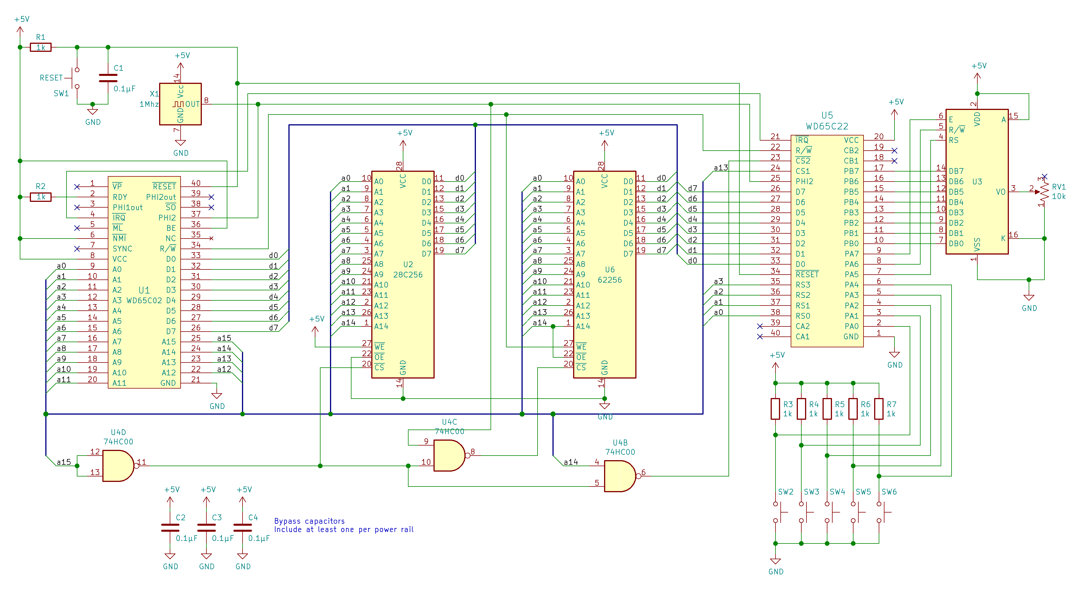
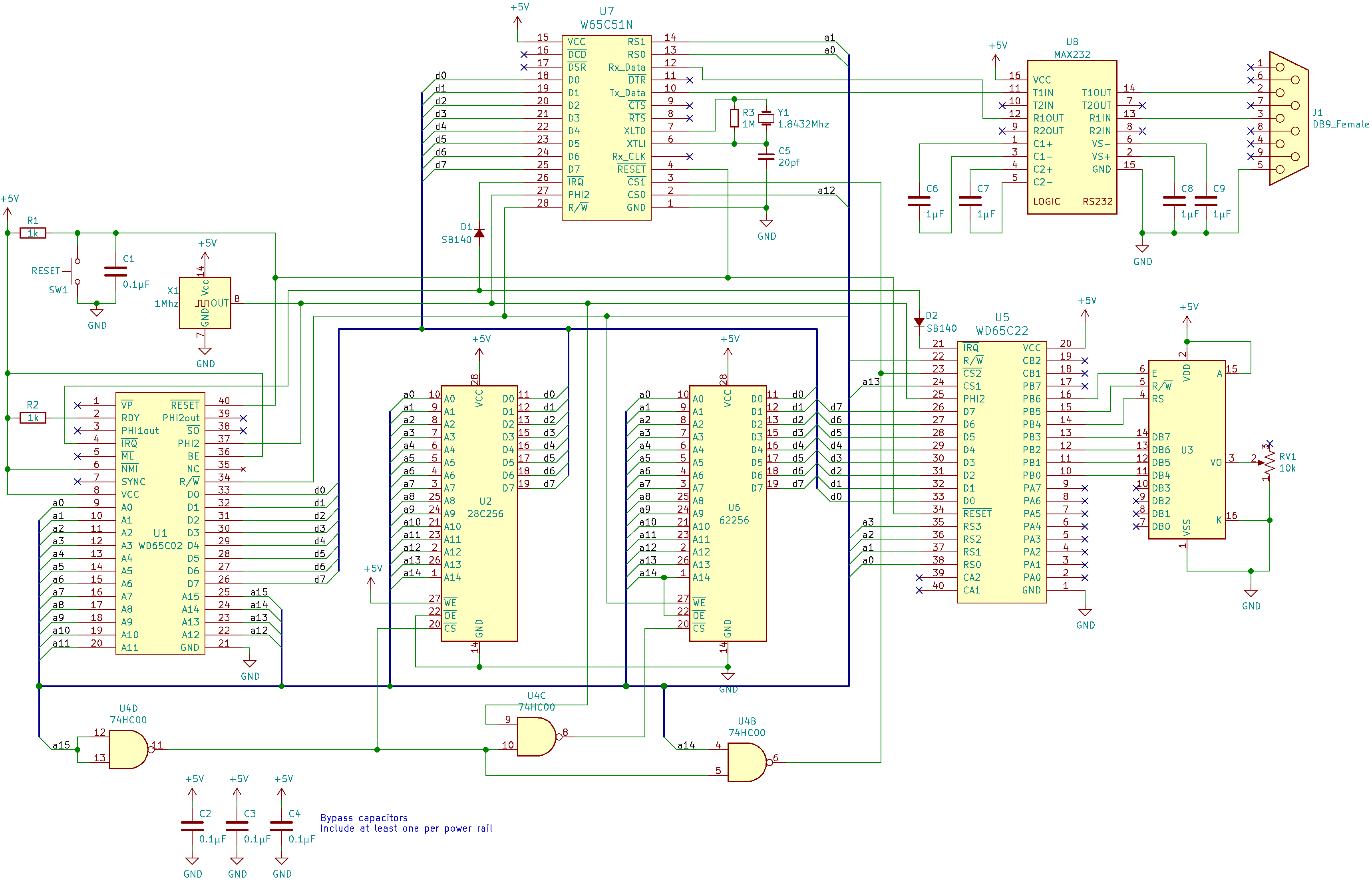
| Chip | Address | Description |
|---|---|---|
| RAM | 0x0000 - 0x3FFF | |
| 0x4000 - 0x4FFF | Unused | |
| UART | 0x5000 - 0x5FFF | |
| VIA | 0x6000 - 0x6FFF | |
| 0x7000 - 0x7FFF | Forbidden | |
| ROM | 0x8000 - 0xFFFF |
| Chip | Address | Description | Installed |
|---|---|---|---|
| RAM | 0x0000 - 0x00FF | Zero Page | V26 |
| RAM | 0x0100 - 0x01FF | Stack | V6 |
| RAM | 0x0200 - 0x02FF | V6 | |
| RAM | 0x0300 - 0x03FF | Input Buffer | V27 |
| RAM | 0x0400 - 0x3FFF | V6 | |
| 0x4000 - 0x4FFF | Unused | ||
| UART | 0x5000 | Data Register | V21 |
| UART | 0x5001 | Status Register | V21 |
| UART | 0x5002 | Command Register | V21 |
| UART | 0x5003 | Control Register | V21 |
| UART | 0x5004 - 0x5FFF | V21 | |
| VIA | 0x6000 | I/O Register B | V3 |
| VIA | 0x6001 | I/O Register A | V3 |
| VIA | 0x6002 | Data Direction Register B | V3 |
| VIA | 0x6003 | Data Direction Register A | V3 |
| VIA | 0x6004 | T1 Low-Order Latches/Counter | V3 |
| VIA | 0x6005 | T1 High-Order Counter | V3 |
| VIA | 0x6006 | T1 Low-Order Latches | V3 |
| VIA | 0x6007 | T1 High-Order Latches | V3 |
| VIA | 0x6008 | T2 Low-Order Latches/Counter | V3 |
| VIA | 0x6009 | T2 High-Order Counter | V3 |
| VIA | 0x600A | Shift Register | V3 |
| VIA | 0x600B | Auxiliary Control Register | V3 |
| VIA | 0x600C | Peripheral Control Register | V3 |
| VIA | 0x600D | Interrupt Flag Register | V3 |
| VIA | 0x600E | Interrupt Enable Register | V3 |
| VIA | 0x600F | Handshake Register | V3 |
| VIA | 0x6010 - 0x6FFF | V3 | |
| VIA | 0x7000 - 0x7FFF | Forbidden | V21 |
| ROM | 0x8000 - 0x???? | BIOS routine | V25 |
| ROM | 0x???? - 0xFDFF | V2 | |
| ROM | 0xFE00 - 0xFFF9 | Wozmon | V26 |
| ROM | 0xFFFA - 0xFFFB | NMI Vector | V11 |
| ROM | 0xFFFC - 0xFFFD | Init Vector | V1 |
| ROM | 0xFFFE - 0xFFFF | IRQ Vector | V11 |
'V' in 'installed' means Video.
1-1_6502_monitor.ino: print each address line signal comes from A0-A15 pins of W65C02S
1-2_6502_monitor.ino: print each address line signal comes from A0-A15 pins of W65C02S only when clock pulse rises
1-3_6502_monitor.ino: Print each address line signals and data line signals from W65C02S only when clock pulse rises
2-1_makerom.py: make every byte of data of EEPROM as 'nop' instruction
2-2_makerom.py: make every byte of data of EEPROM as 'nop' instruction except the places where start address is stored
2-3_makerom.py: make every byte of data of EEPROM as 'nop' instruction except the places where start address is stored, and write some instructions from 0x8000
2-4_makerom.py: make every byte of data of EEPROM as 'nop' instruction except the places where start address is stored, and write some instructions(init and loop) from 0x8000
3-1_compare.s: make same code of video 2 using Assembly language (w/ '.org', '.word')
3-2_compare.s: make same code of video 2 using Assembly language (w/ '.org', '.word', lable)
3-3_blink.s: this code makes LED bulbs blink left to right
4-1_hello_world.s: print "hello, world!" using I/O controller and LCD monitor connected
5-1_hello_world.s: print "hello, world!" using subrutine w/o memory - so, not working
No code
7-1_hello_world.s: print "hello, world!" using subrutine w/ memory, and clear display instruction added
No code
9-1_hello_world.s: print "hello, world!" using 750 'nop' instructions to give enough time to LCD monitor to execute initialization instructions
9-2_hello_world.s: print "hello, world!" checking busy flag to give enough time to LCD monitor to execute instructions
9-3_hello_world.s: print "hello, world!" w/ refactored print_char subrutine
10-1_binary_to_decimal.s: print decimal number using algorithm for binary division
10-2_binary_to_decimal.s: print decimal number w/ algorithm for reversing the number
11-1_interrupt.s: interrupt counter using irq handler
11-2_interrupt.s: interrupt counter using nmi handler
12-1_interrupt.s: interrupt counter using irq handler w/ I/O controller
12-2_interrupt.s: interrupt counter using irq handler w/ I/O controller and delay to get rid of switch bouncing problem
No code
¡Cautions! All pins of PORTA, which was partly a output pins for LCD monitor, is now used to read input data from keyboard. To solve this problem, Ben Eater changed the hardware and the code without mention it in public video. To get every changes, I played and stopped in very short interval(25:48-25:50 in the video) and looked up a final code(keyboard.s), which is gonna be completed in later video, by Ben Eater.
According to datasheet, D0-D3 pins are not used during 4-bit operation. Considering the changed code shown in the video, he may connected DB4 to DB7 of LCD to PB0 to PB3 of I/O controller. And RS to PB4, RW to PB5 and E to PB6. I guess PB7 isn't used as an important pin in this video.
14-1_keyboard_irq.s: shows transmitted protocol data from keyboard continuously using irq handler w/ I/O controller
15-1_keyboard_irq.s: shows transmitted characters from keyboard continuously w/ keymap
15-2_keyboard_irq.s: shows transmitted characters from keyboard continuously w/ keymap - release key & duplicated key data dealt
15-3_keyboard_irq.s: shows transmitted characters from keyboard continuously w/ keymap - release key & duplicated key data dealt, shift key dealt
¡Cautions! '16-2_sensor.s' code is not completed.
16-1_sensor.s: receives data sent from sensor continuously
16-2_sensor.s: receives data sent from sensor continuously (not working, full-code not provided)
17-1_delay.s: simple delay with single loop
17-2_delay.s: simple delay with double loop
17-3_delay.s: delay w/ I/O controller(W65C22) timer in one-shot mode
17-4_delay.s: delay w/ I/O controller(W65C22) timer in free-run mode ('update_lcd' update needed, full-code not provided)
18-1_rs232.s: shows characters that comes from DTE
No code
20-1_rs232.s: sends hardcoded character and shows characters that comes from DTE
21-1_uart.s: connects CPU to UART chip which is connected to RS-232 serial interface
22-1_uart.s: receives data from UART chip which is connected to RS-232 serial interface
22-2_uart.s: sends & receives data from UART chip which is connected to RS-232 serial interface(not working, because of a hardware bug)
22-3_uart.s: sends & receives data from UART chip which is connected to RS-232 serial interface(fixed the hardware bug)
wozmon.s: The WOZ Monitor for the Apple 1
23-1_adapted_wozmon.s: The WOZ Monitor for the Ben Eater 6502 Computer
23-2_hello_would.s: shows "Hello, would!"(intentional typo), which is gonna be mounted together with the WOZ Monitor program
Also, you'd better(but not necessarily) watch together "How Wozniak’s code for the Apple 1 works", although it's not included in Ben Eater's 6502 playlist.
24-1_adapted_wozmon.s: The WOZ Monitor for Ben Eater 6502 Computer
adapted_wozmon.s: Now it only contains WOZ Monitor code
bios.cfg: tells linker how to allocate the code in ROM/RAM etc
bios.s: simple bios file
All changed codes from original codes are included.
All changed codes from original codes are included.
Only adapted_wozmon.s, bios.s, defines_eater.s and eater.cfg has been changed from previous video.