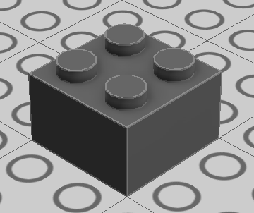
Brick outlines

The outlines seen on bricks in LDD (when the option is enabled) are actually defined in the mesh files (*.g).
The outlines are defined by a set of six texture maps which applies a square image with a line on each triangle.
Theses six texture maps are actually processed as three pairs for each triangle for a purpose I will explain later.
The shader that draws the outlines uses these three images:


 *The actual images are only 4x4 pixel and upside-down (they are flipped when rendering)
These images are mapped onto a triangle according to the three pairs of 2D coordinates defined in the outline data of the mesh.
An outline will be drawn when the amount of blue and/or red is above a certain threshold.
Why is there three images you ask? The answer is that they are used to control how the two lines of a pair will be combined.
They can combined either by "union" or "intersection". I will explain later why it is needed.
The shader starts off by finding out which triangle is being drawn and fetches the outline data of this triangle.
It then process each pair of 2D coordinates like this:
- Get the color of image 1 with the first coordinate
- Choose between image 2 and 3 according to the sign of the value of X of the second coordinate
- Get the color of selected image (2 or 3) with the second coordinate
After that, some stuff is done to the obtained colors to obtain an "outline threshold" value. My brain melts each time I try to follow through the code.
The only thing that is important to remember is that the second pair is used to determine if the two coordinates of a pair should be combined by union or intersection.
A negative value of X in the second pair will make an union.
A positive value of X in the second pair will make an intersection.
The first thing to have in mind is that the outlines are not lines drawn with a thickness.
To make things simple, think of them as an infinite virtual line that splits a triangle in two: the upper half is drawn as normal and the bottom half is drawn as an outline.

The easiest way to understand how union and intersection works and also to understand why issues can occurs is to use an example.
Let's take a look a this example model representing an L plate (2420):

The thick outlines are the border of the model where an outline needs to be drawn.
The green area is (a portion of) the expected outline to be drawn.
Now let's focus on the outlines for the inner corner. Triangles #1 and #6 are straight foward and so are #2 and #5.
The reason we need union and intersections is when we have cases like triangle #3. This triangle is connected to two outlines.


Image #1 represents how the texture coordinates would be mapped for the two inner outlines
Image #2 shows how the outlines would be drawn on the triangle if we combined the textures by union
Image #2 shows how the outlines would be drawn on the triangle if we combined the textures by intersection
By this point I'm sure you get the idea that union and intersection are crucial to properly draw outlines.
Take a look on how it can have disastrous effect on triangle #5:


As you can see, if an union is used, all of the triangle would be drawn as an outline.
From the previous examples, you may think that it is easy to select which edges needs to have outlines, which ones applies to a triangle and finally how to combine them to produce the right outlines.
The truth is that it is far more complex then that. The previous examples have simple geometry and are only 2D.
All of this becomes really abstract when you process lists of 3D points.
The process of determining which edges should draw an outline on a triangle is not easy. This is why issues and glitches occurs.
Most issues with generated outlines comes from bad model topology.
Outlines are generated when the faces shared by an edge are not flat or when an edge has only one face attached (e.g. edges of a plane, should not occur in practice)
Make sure that the vertices shared by two surfaces are not merged. They need to have dirrent normals.
The following topology is often seen in models imported from LDraw:

The bad topology has a triangle with an edge near a gap that needs an outline but it also goes through the whole model. Drawing an outline on this edge will produce unwated lines on both side of the gap.