ServoTester, a Arduino project to verify RC-servo function / ein Arduino Projekt zur Überprüfung von RC-Servo Funktion
Beim Erstflug eines 10kg Segler wurde das Modell plötzlich schneller. Steuerkorrekturen am HR-Hebel am Sender zeigten keinerlei Wirkung. Nach ca 20s verschwand das Modell hinter der Hangkante. 3 Tage später konnte das Modell aus 20m Höhe von einem Baumkletter geborgen werden. Da der Rumpf annähernd unbeschädigt war, konnte die Fehleranalyse beginnen und bald war klar, es war der nagelneue HR-Servo. Der Servo lief in Post-Absturz-Tests eigentlich ganz gut, aber zeigte aber plötzlich Aussetzer. Ein Y-Kabel vom Empfänger-HR-Ausgang zum HR-Servo und zu einem zweiten Referenzservo brachte endgültige Klarheit. Der eingebaute HR-Servo zeite sporadische Aussetzer, die der Referenzservo nicht zeigte. Ein sehr unangenehmer Fehler. Während der Bau- und Einstellzeit des Modells zeigten sich keinerlei Probleme und sporadische HR-Tests waren immer erfolgreich. Auch während der ersten 69 Minunten Erstflugzeit, waren keine Probleme erkennbar. So kam mir die Idee einen ServoTester zu bauen, der über einen längeren Zeitraum (2 Stunden) den Servo in unterschiedlichen Positionen anfährt und die Servohebelposition überprüft.
At the first flight of a 10kg glider after about 70 minutes, the model slowly gots faster. Moving the elevator stick has no reaction. After about 20 seconds the model disappears at the hill side. 3 day later the model could be salvaged form the top of a tree. The fuselage was fortunately not damaged. The error analysis was completly clear: The servo for the elevator has dropouts. Not often but when moving the elevator stick I had the feeling the servo does sometimes not move correctly. Putting an Y-cable with a second servo connected to the elevator receiver output, showed the error clear. The elevator servo sometimes does not move. This is a very bad error. At the building and setup phase of the modell, I had no indication of this and a single or short movement test was always successful. So the idea of a servo tester, which runs a servo movement test procedure for a long time (2 hours) and a continous servo position check to verify the correct position was born.
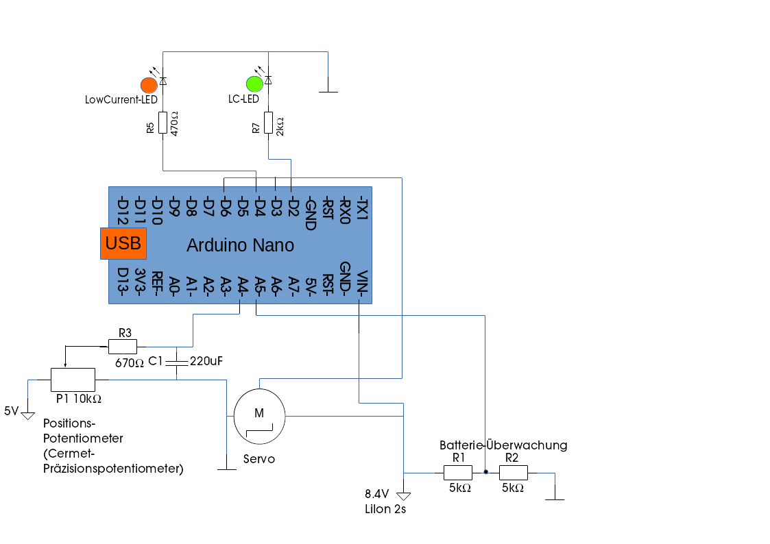
Die Konzeptidee ist sehr einfach. Der Mikrokontroller, erzeugt PWM Servosignale (1.0us - 2.0us Impulse) an einem digitalen Ausgang. So kann der Servo gesteuert werden. Der Positions-Sensor/-Potentionmeter ist ein Spannungsteiler, dessen Spannung am Pin des beweglichen Teils ein Maß für die Position ist. Der Arduino hat mehrere einfache ADCs (Auflösung 1024), die benutzt werden können, um diese Spannung zu messen. Ein weiterer Spannungsteiler unterstützt als Sicherheitscheck eine Batterieunterspannungs-Warnung/-Abschaltung und 2 LEDs dienen als einfache Statusmelder. Zusätzlich werden an der USB-Schnittstelle Textnachrichten ausgegeben. Die Verarbeitungslogik ist als Arduino Sketch in C++ hier hinterlegt.
The concept of the project is simple. The microcontroller, is able to send valid PWM servo signals (1.0us - 2.0us pulses), to a digital output. So the servo can be controlled. The postition sensor/potentionmeter is a voltage divider, the voltage at the moving pin is an indicator for the position. The microcontroller has some build in simple ADCs (1024 resolution), which can be used to measure this voltage. A separate voltage divider can provide a safety check for a battery low voltage warning/shutdown and 2 LEDs are used as simple status indication. Additionally there are text messages sent to the USB interface. The logic is build as Arduino sketch based on C++ code as given here.
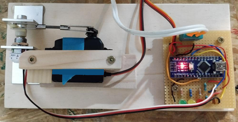
Außer einem Arduino Nano, ist nicht viel notwendig. Zwei Status LEDs (low current LED), um ein simples Benutzerinterface zu realisieren und ein hochwertiges Cermet Potentiometer, das als Positionssensor dient und mechanisch mit dem Servoarm des Servos verbunden ist. Dazu kommen noch ein paar Widerstände und ein Kondensator, wie im Schaltplan dargestellt.
in addition to the Arduino nano hardware only some electronic parts are needed to create a human machine interface (only 2 status low current LEDs) and a high quality potentiometer (Cermet precision potentiometer) is needed as a position sensor, which is mechanical connected to the RC-servo. Some resistors and a capacitor as shown in the circuit diagram.
Der Arduino gibt detaillierte Benutzernachrichten an der seriellen Schnittstelle (USB) aus. Wenn der Arduino über die USB-Schnittstelle an einen PC angeschlossen wird und ein Programm zur Kommunikation mit der seriellen Schnittstelle verfügbar (minicom/putty/ArduinoIDE-Serial monitor) ist, kann bei einer Baud-Rate von 57600 baud mitgelesen werden.
The Arduino will give usefull detailed information on the serial output. So if you connect the Arduions USB connectior with your PC and you have a serial communication programm like minicom/putty or so with a baud rate of 57600 you can see this detailed information
- grüne und rote LED blinken synchron: ServoTester ist in Initialisierung
- grüne und rote LED blinken abwechselnd:
ServoTester
ist in Initialisierung und hat temporären Probleme:
- obwohl der Servo-Hebel in Mittelstellung ist, ist der Positionssensor nicht in Mittelstellung (Gestänge stimmt nicht und/oder Servohebel zeigt in Mittelstellung nicht senkrecht nach oben )
- obwohl sich der Servo-Hebel leicht bewegt, kann diese Bewegung am Positionssensor nicht detektiert werden.
- grün blink langsam (1.5s): es ist ein nicht behebarer Fehler während der Initialisierung aufgetreten, Test wird nicht gestartet. Neutstart durch Reset-Button oder Stromzufuhr.
- grün leuchtet dauerhaft: Test Prozedur läuft normal
- rot blinkt, während grün dauerhauft leuchet: Jeder rote Blinkzyklus entspricht einer fehlerhaften Positionsprüfung. Das sollte bei einem funktionierndem Servo und einer ordentlichen mechanischen Verbindung Servo-Sensor nicht auftreten.
- grün leuchtet, hat aber kurze (0.5s) Aus-Phasen: Test Prozedor ist
beendet.
- rot is dabei Aus: Test wurde erfolgreich beendet ohne Fehler
- rot blinkt: Test wurde beendet mit Positionsfehler. Anzahl der Blink-Phase entspricht dem Anzahl an fehlerhaften Prüfungen.
- Green and Red LED blink synchronously: ServoTester is in initialization
- Green and Red LED blink alternately:
ServoTester
is in initialization, with temporary problems :
- although the servo is in middle position, the servo position sensor is not (offset in mechanical coupling)
- although the servo does move a little around the middle position, the servo position sensor does not dectect correct movement
- Green blinks slow (1.5s): there was an unrecoverable initialization fault, test procedure will not start
- Green is on: Test procedure is running
- Red blinks while Green is on: Each red blink cycle represents one failed position check. This should not happen for a correct operating servo and a valid mechanical connection between servo and sensor
- Green is on, but there is a small (0.5s) off phase: Test is
finished.
- Red is off: Test is finished without an position error
- Red blinks: Test is finished with an position error(s). Count of blink phases indicates the error count
Der ServoTester muss an eine 2s LiIon Batterie angeschlossen werden. Die Nutzung eines Labornetzgerätes ist möglich, jedoch ist darauf zu achten, dass nicht mehr als 8.4V Spannung angelegt wird und dass eine Stromstärke größer 1 Ampere eingestellt wird, da beim Servo-Speed-Test hohe Ströme (je nach Servo) angefordert werden. Der Arduino Nano kann optional mit der USB Schnittstelle eines PC verbunden werden, um neue Firmware auf den Arduino zu laden oder um Textnachrichten an einen seriellen Monitor zu übertragen. Wenn die Batterie mit dem ServoTester verbunden wird, wird :
- der Servo in Mittelposition gefahren.
- wenn der Positionssensor die Mittelposition dedektiert, wird durch eine leichte Bewegung des Servos, die Bewegung des Sensors getestet.
- in dieser Phase kann der Servohebel in der korrekten Position auf die Achse montiert werden.
- im nächsten Schritt werden die Servopositionen (+/-100%) kalibriert.
- danach wird ein Servo-Speedtest durchgeführt, bei dem der Servo von 0% auf +/-100% in maximaler Geschwindigkeit gefahren wird. Die Zeit bis zum Erreichen der Endposition wird als Textnachricht ausgegeben.
The tester has to be connected to a 2s LiIon battery. Optional the Arduino can be connectd via the USB interface to upload new firmware or to transfer textual information, about the servo test. When the battery is connected the ServoTester, first does:
- set the servo to middle positions, if the sensor is not in middle position an temporary error is indicated. Move arm and lever to middle position
- if the sensor middle position is dedected, the ServoTester does some smooth servo movement and tests if the movement is dedected at the sensor.
- in this phase you can mount the servo arm in the right position to the servo shaft.
- the next step is calibration of the servo movement (+/-100%)
- after this, a servo speed test is done, which moves the servo from 0% to +/-100% at maximum speed. The time till reaching the end positions is measured and given as a text message.
Generated by
 1.8.14