This repo shows how to to use USB writes to control the QA40x hardware. There are four ways of controlling the QA40x hardware:
QA40x Application: This allows you to make measurements in a self-contained environment. No coding required.
Tractor: Tractor is a standalone application that controls the QA40x application via REST. The application allows you to quickly build test scripts, specify pass/fail windows for measurement results and permit logging to databases. The scripts can also include operator instructions to allow manual testing by playing a WAV file (for example). This allows factory personnel to verify if pots are scratchy, for example. Tractor doesn't require any coding for standard tests.
QA40x REST: This allows you to control the QA40x hardware via the QA40x application. The control occurs via REST calls. This requires proficiency im writing software. But the software is commonly used protocols used for setting and retrieving data remote web servers. This means the techniques are widely known across across a range of languages. The specialization required here is low.
Bare Metal: The Bare Metal interfaces is a USB register-based interface for directly controlling the hardware. There are 4 endpoints to the QA40x hardware. Two endpoints facilitate register read/write. And two endpoints facilitate data read/write. You put the QA40x hardware into a specific mode via register writes. For example, you might set the max input level to 6 dBV using a register write. And once you have set the hardware up as desired, you stream data to the DAC and stream data back from the ADC. The code in this repo shows how to do this. The code is liberally commented, but feel free to ask a question on the forum if not clear. Note that the language used is C#, and the LibUsbDotNet library is used for the USB reading and writing. Underneath the covers, the LibUsbDotNet uses LibUsb, which is a cross-platform library for Windwows, Linux and Mac. There are lots of wrappers for LibUsb, meaning C#, Python and other languages can readily use the library.
The sample code in this repo performs overlapped IO. That is, you tell an operation to start (by sending a USB packet) and then later to check to see if the operating is complete. In the interim, you can do other work. If you are not familiar with overlapped IO, this code will be frustrating because it's quite a bit more involved than, say, Serial Port code where you are blocking on operations. Addtionally, the code makes use of C# async programming model. This can be a bit confusing if you've not seen it before. Microsoft has a very good tutorial HERE that might be helpful to building an understanding. But in a nutshell, if you see the keyword await that means that the code will pause until the function/method/task is complete. But it also means the thread isn't completely blocked--it can still perform work in other places that isn't dependent on the completion. This means your UI "stays alive" in most places even though it might be blocked at an await.
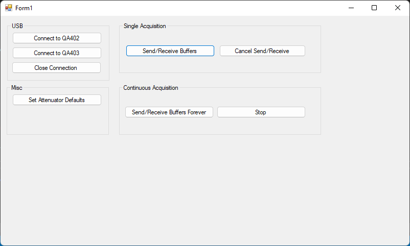
The UI for the test app is shown below.
You can adjust the size of the buffers used for acquisition by sending the DoStreamingAsync() function different array lengths. For example, in the code below, you can see two sines are being generated at line 103 and 104--one for the left channel and one for the right channel. The left channel has a 1Vrms 1 kHz tone, while the right channel has a 1Vrms 2 kHz tone.
At line 114, the buffers are submitted to start the acquisition. It should be clear how to make the buffers larger or smaller.
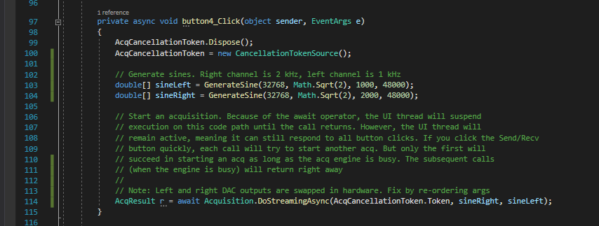
The CancellationToken is a C# pattern used to cancel async operations. If you don't anticipate needing the ability to cancel an acquisition, your DoStreamingAsync() function can leave it out entirely.
Note in the Acquisition.cs file the DoStreaming() function has a few places where "magic numbers" are used on the submitted buffers. The first place is shown below:
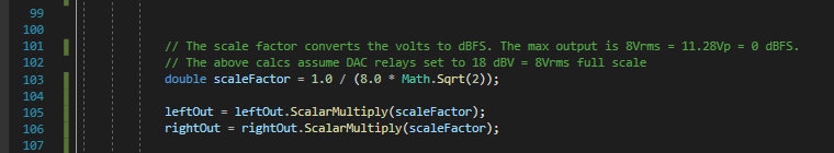
In the code above, the data submitted by the user is expected to be volts. That is, if you generate a sine with 1.41*Math.Sin() then the peak value will be +/-1.41V, and the RMS of that sine will be 1Vrms or 0 dBV. The code above is converting the absolute voltage to dBFS. Since the max output of the DAC is 8Vrms = 11.28Vp, that means that, roughly, the 11.28V tip will need to be scaled to +1, and the -11.28V tip will need to be scaled to -1. This is because the DAC accepts values spanning from +1 to -1.
So, the code above scales the user data from volts to dBFS. Now, the assumption here is that the max output is 18 dBV. If you set the relays such that the max output is 8 dBV, then you will another scaling factor. And another one for -2 dBV max output, etc.
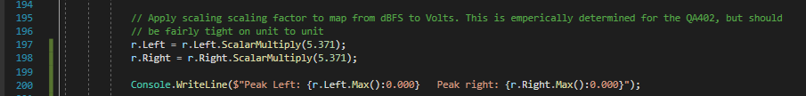
For the input side, there's a similar operation happening but it's a bit more random looking. That takes place at the bottom of the DoStreaming() function. Again, depending on the input range you've selected (0, 6, 12, 18, 24, 30, 36, 42 dBV), this adjustment might need to change a bit.