camera calibration
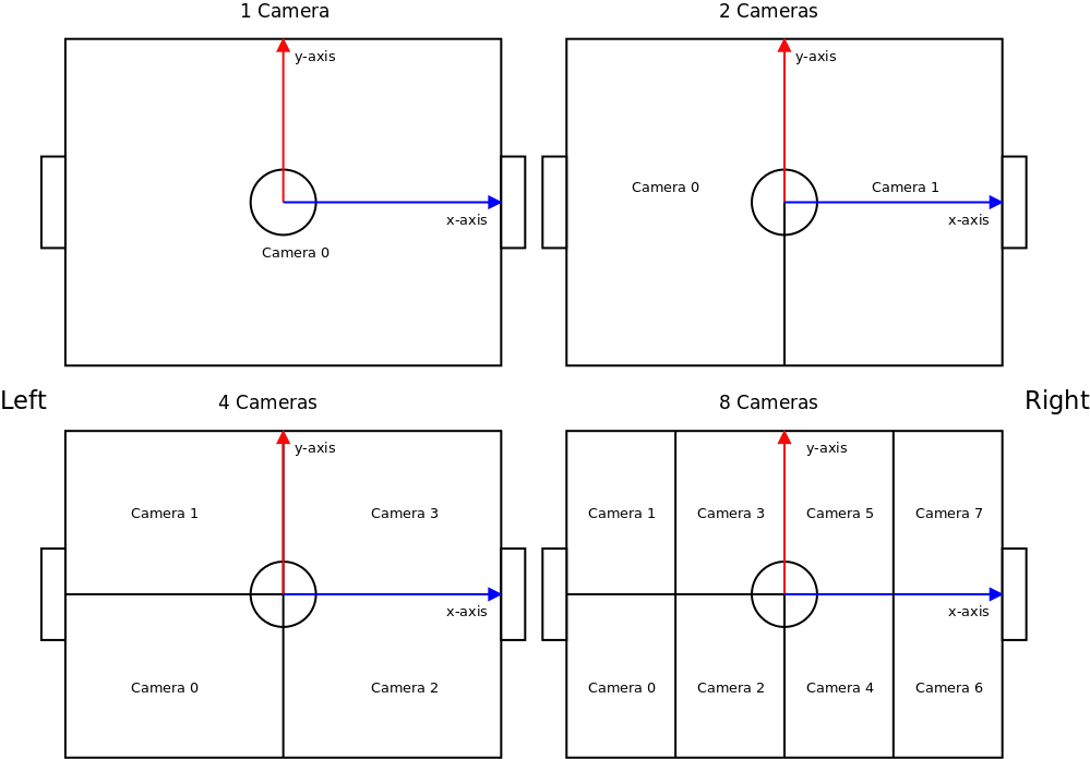
The cameras and the coordinate system in ssl-vision are set up as shown in the following figure. One instance of ssl-vision supports up to four cameras. Cameras are numbered from negative to positive coordinates.
The field markings are specified as two lists, one of named line segments, and one of named circular arcs. To add / remove markings, change the number under the "Number of Line Segments" or "Number of Arcs" text entry. To automatically generate those markings from the global field configuration, click the "Update" button.

The default field markings are as prescribed in the rules book of RoboCup SSL
In the league, we refer to the different field sizes as follows:
- standard field: 4m x 6m (until RoboCup 2014)
- double sized field: 6m x 9m (RoboCup 2015 - RoboCup 2017, since RoboCup 2018 for division B)
- quad sized field: 9m x 12m (since RoboCup 2018 for division A)
First, configure the field dimensions (in mm) in the global field configuration as shown above and press the "Update" button to apply the dimensions to the field markings. You can also adapt the field markings manually by adding/changing line segments or arcs. Those markings are used for line detection.
Teams can read those markings from the geometry package that is send with the Protobuf Wrapper message. The default markings used for RoboCup 2018 are:
Lines:
- TopTouchLine
- BottomTouchLine
- LeftGoalLine
- RightGoalLine
- HalfwayLine
- CenterLine
- LeftPenaltyStretch
- RightPenaltyStretch
- LeftFieldLeftPenaltyStretch
- LeftFieldRightPenaltyStretch
- RightFieldRightPenaltyStretch
- RightFieldLeftPenaltyStretch
Arcs:
- CenterCircle
Log files from 2017 and before will additionally contain four more arcs four the legacy penalty area:
- LeftFieldLeftPenaltyArc
- LeftFieldRightPenaltyArc
- RigthFieldLeftPenaltyArc
- RightFieldRightPenaltyArc
First, choose one of the camera tabs that is backed by a camera. It does not matter, which camera is assigned to which tab and not all tabs have to be used.
Choose the correct camera id according to the numbering schema shown above and enter it into the "Global camera id" text field, then press "Update control points". This will update the expected field coordinates of the four control points. You can check and update them under "Camera i / Camera Calibrator / Calibration Parameters / Control point j", if required. To move the control points around in the image, make sure that the "Calibration" option under visualizations is checked, and that the camera calibration tab on the right is active.
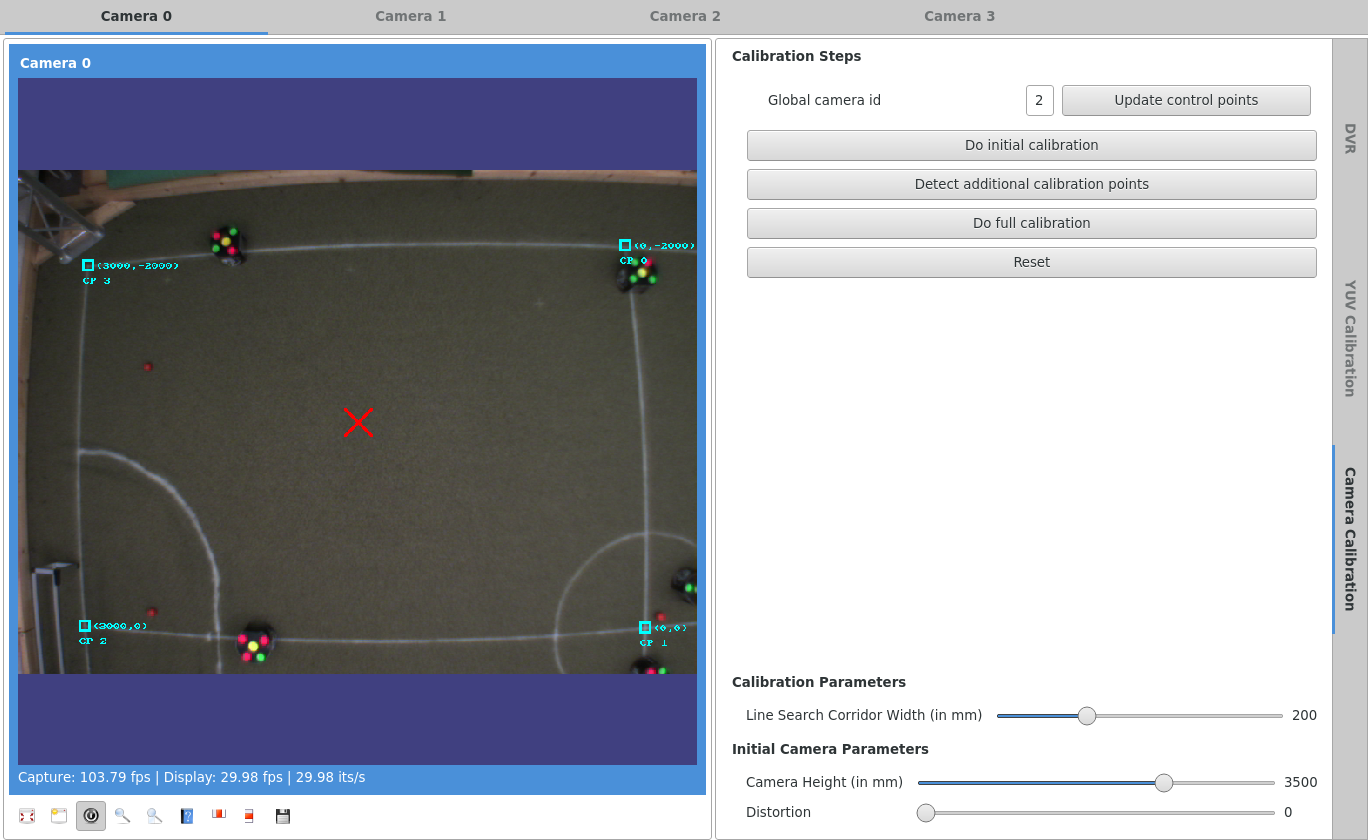
- Enable the camera visualization and check the "camera calibration" and "calibration result" options.
- Select the camera calibration tab on the right, and click on "Reset".
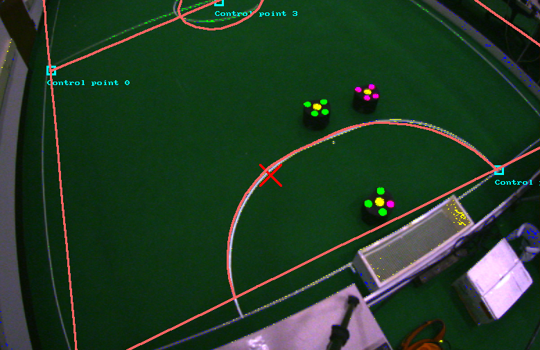
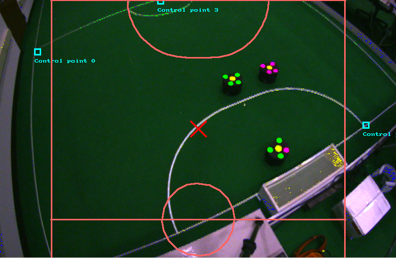 3. Drag the control points to the locations in the image that correspond to the specified world locations. In the screenshot below, the control points include the center of the field and the intersection of the defense arc and the goal line.
4. Click on "Do Initial Calibration".
3. Drag the control points to the locations in the image that correspond to the specified world locations. In the screenshot below, the control points include the center of the field and the intersection of the defense arc and the goal line.
4. Click on "Do Initial Calibration".
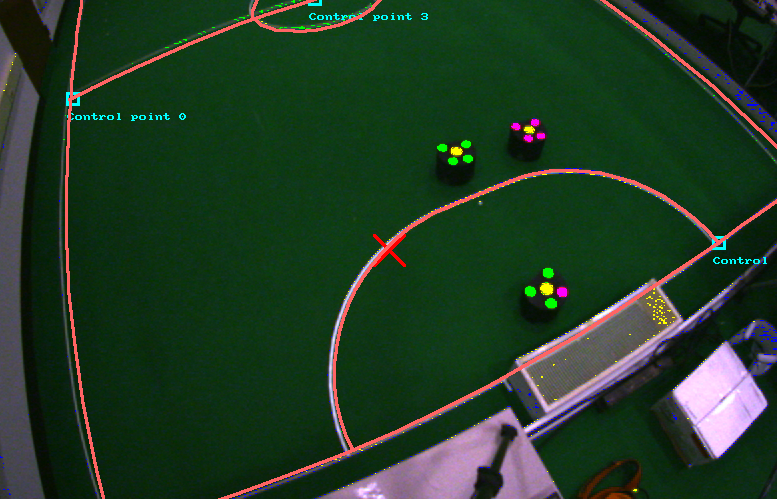
 6. Drag the camera height and camera distortion markers till the calibration result roughly approximates the actual field lines. Click on "Do Initial Calibration" again to update the initial calibration guess. Repeat to refine if required.
 8. Under the visualizations, turn on "Detected edges" and drag the "Line Search Corridor Width" slider on the calibration tab to increase the search corridors till they include the field markings. Click on "Detect additional points".
 10. The detected edges will be displayed. Now click on "Do full calibration" to calibrate using all detected points.
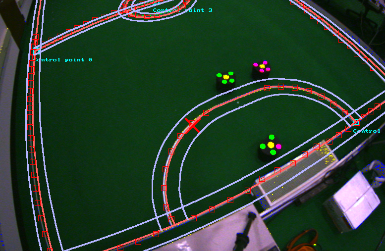
11. If necessary, repeat the last 2 steps with a smaller corridor width to refine the calibration result. The final result should match will with the image, as shown below.
10. The detected edges will be displayed. Now click on "Do full calibration" to calibrate using all detected points.
11. If necessary, repeat the last 2 steps with a smaller corridor width to refine the calibration result. The final result should match will with the image, as shown below.
Note: Not yet on master, see #163
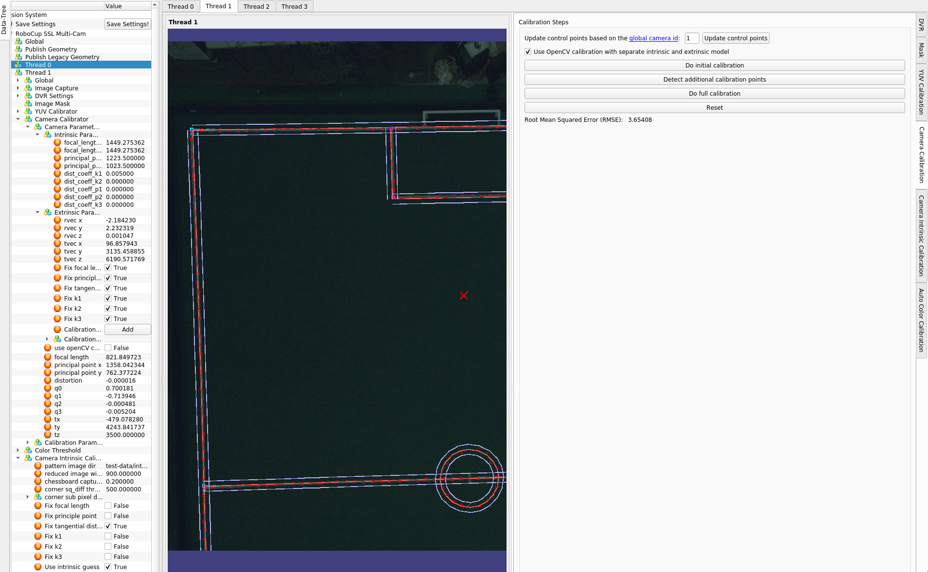
The calibration can alternatively be performed using the OpenCV model by toggling the respective checkbox in the camera calibration view. The differences are as follows:
- The camera model is explicitly divided into the intrinsic and extrinsic model
- The intrinsic model can be calibrated separately using for example a chessboard pattern (there is a separate tab next to camera calibration with instructions) or by entering the parameters manually (from datasheet and/or calculation)
- For both models, certain parameters can be fixed during optimization (in the config tree) to have more control on the calibration
- The "Detect additional calibration point" button generates additional calibration points (magenta) that can be moved like the cyan ones and are used for the full calibration.
- The "Do full calibration" button will primarily calibrate the extrinsic model, but can also fine-tune the intrinsic model. This can be controlled in the config tree as well.
The following image shows the available options and the result: