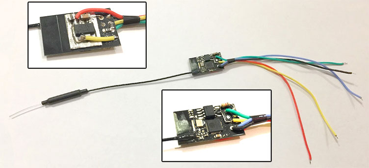
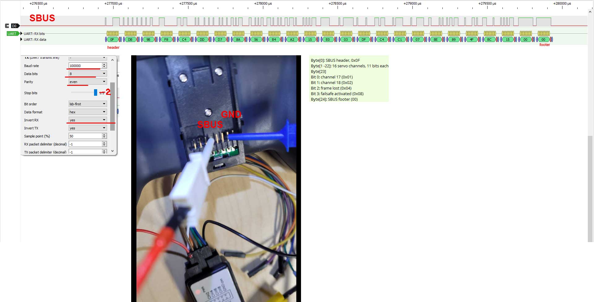
Receiver to be used with flight controller. Receives 15 channels and outputs SBUS signal. Transmits bidirectional transparent telemetry stream (can be used for Mavlink, LTM, MSP etc.).
RSSI is injected into channel 16.
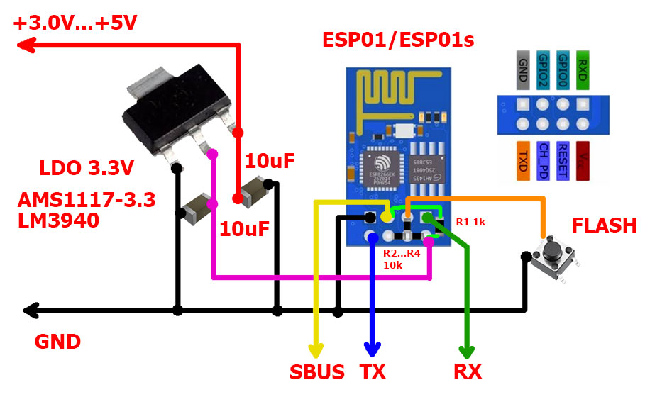
Can be powered from 5V BEC or directly from 1S battery (3.0V...5.0V). If you are going to power it from 1S battery, linear regulator should be low-drop one (0.2...0.3V at 170mAh). ESP8266 will operate stable down to 2.7V, allowing dischaging battery down to 3V.
Peak power consumption is ~170mA.
See testing with INAV 1.7.3 flying wing: https://www.youtube.com/watch?v=UptvxsFHDFA
TODO: support sensors pooling for Smartport telemetry.
TODO: work as telemetry blackbox?
Failsafe flag is passed in SBUS packets. Channels retain last good values.
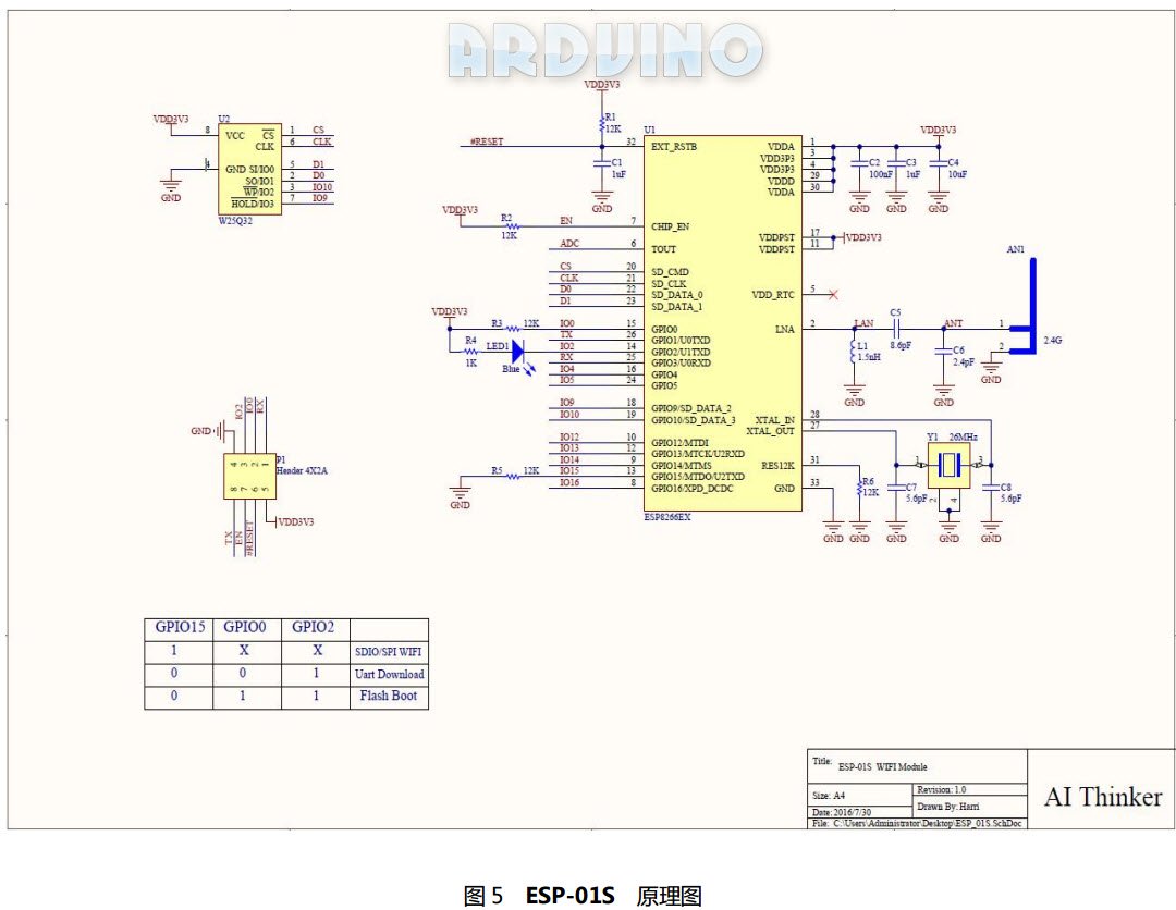
- ESP01s (recommended) or ESP01 board
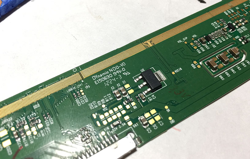
- 3.3V LDO SOT223 (AMS1117-3.3, LM1117-3.3, LM3940 or other)
- 1x 1k 0804/1206 smd resistor, or 1/8W resistor
- 2x 1206 10uf capacitors
- 3x 10k 0804 smd resisors (not required for ESP01s)
- dipole or whip antenna (optional)
- a button
- USB-UART-TLL convertor or ESP01 breakout board (for initial flashing)
10K pullup resistors are not required for ESP01s board. Should be installed on ESP01 boards only.
SBUS output is GPIO2. If GPIO2 is pulled down, ESP board boot fails. Typical SBUS invertor schematix on flight controller includes 1k resistor to the base/gate of transistor and 10k pulldown resistor from base/gate to GND. Effectively, GPIO2 is grounded. The easiest way to solve this is to add 1k pullup resistor.
If ESP is still not able to boot, and boots with GPIO2 disconneted from FC, then R1 value should be decreased, down to 470 Ohm. Alternativelly, connect GPIO2 to FC through diode (cathode to ESP01).
-
Desolder all pins from ESP01 board
-
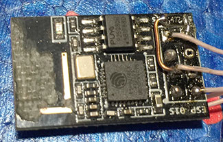
Solder R2...R4 ( not required for ESP01s)
-
Solder R1
-
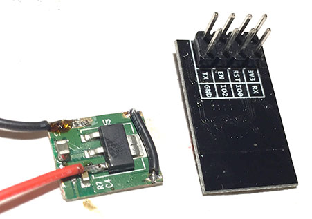
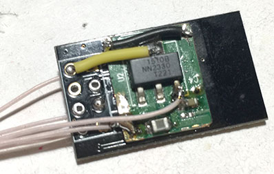
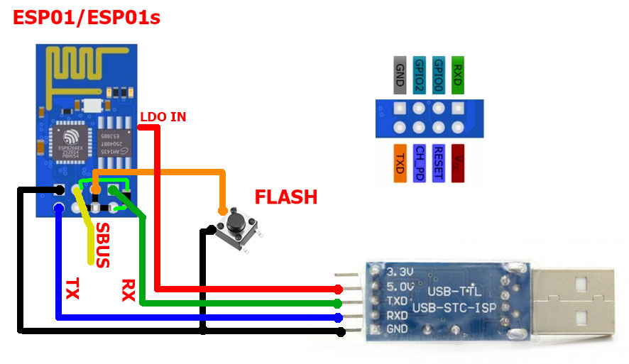
Glue 3.3V LDO or small PCB with 3.3 LDO to the back of ESP01. Connect according to connection diagram above.
If FC has BEC which can provide 3.3V 170mA, LDO may not be required.
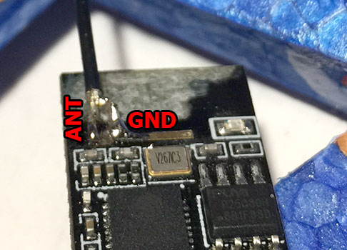
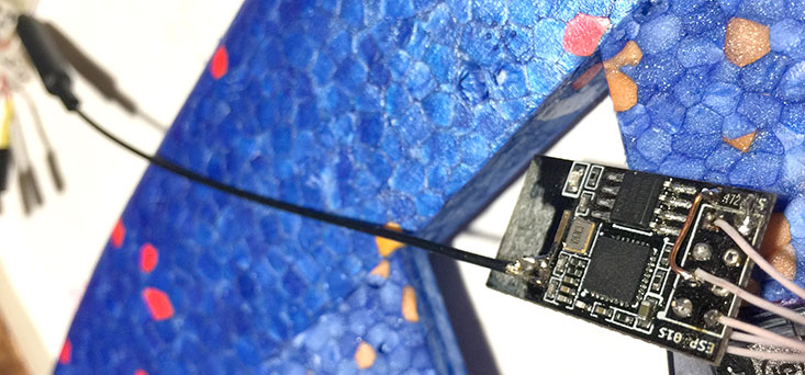
- Remove PCB antenna using dremel, leaving two small pins only:
- Solder dipole or whip antenna
-
Glue antenna wire using some epoxy
(steps 5...7 are optional. PCB antenna can provide range ~100m).
-
Flash firmware
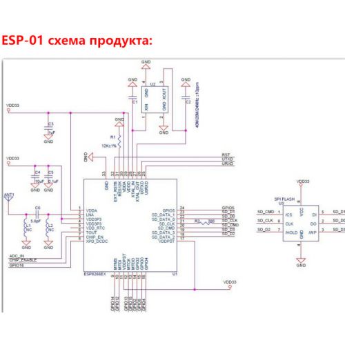
Make sure you flash correct firmware. There are 3 types of ESP-01 board. See reference section below. Use esp01 or esp_1m firmware accordingly.
- Edit receiver configuration: examples/rx_esp01_sbus/include/rx_config.h
- configure key and wifi channel: USE_KEY and USE_WIFI_CHANNEL
- configure telemetry baudrate
- Temporary solder flash button according to connection diagram above.
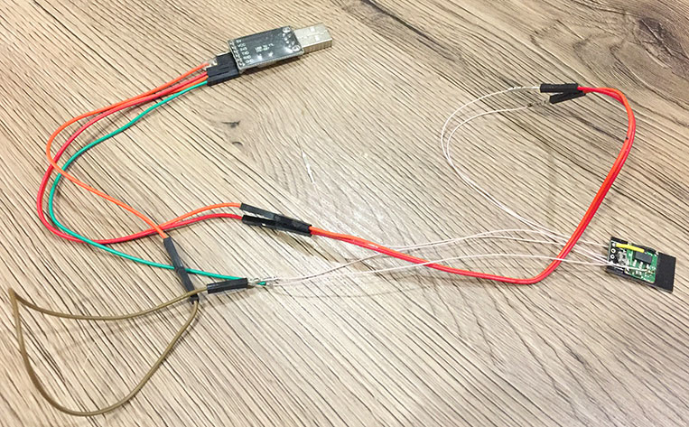
- Connect to USB-UART adapter according the connection diagram below:
- Plug USB-UART adapter while holding FLASH button. Upload examples/rx_esp01_sbus/ project using PlatformIO.
Optionally, you can flash firmware before soldering anything using some ESP01 breakout board.
From my experience, FC serialpathrough mode does not work for flashing.
After initial flashing, firmware can be updated wirelessly (OTA).
When transmitter is not working, it is possible to update receiver.
- Connect to access point "hxrcrsbus" without password.
- Uncomment:
upload_protocol = espota

upload_port = 192.168.4.1
lines in platformio.ini.
- Build and upload using PlatformIO IDE as usual.
There are 3 types of ESP-01 board:
- ESP-01 blue board: 512Kb flash, 2 LEDs (red power LED, blue LED on TX )
- ESP-01 black board: 1Mb flash, 2 LEDs (red power LED, blue LED on TX )
- ESP-01s black board: 1Mb flash, 1 LED ( blue LED on GPIO2 )
Determine your board type by checking installed flash chip. F.e. T25S80 is 1Mb chip.
