ROS tutorial by Purdue SMART lab: Husky mobile robot navigation and creating custom robots with sensor plugins in Gazebo simulation.
The tutorial instructions are also available on the wiki page of this repository: https://github.com/SMARTlab-Purdue/ros-tutorial-robot-control-vision/wiki
Gazebo is a powerful robotic simulator that allows us to customize robot models to fit your research. Gazebo offers physics simulation at a much higher degree of fidelity, a suite of sensors, and interfaces.
This tutorial serves as an introduction to driving and controlling robots (e.g. Husky robot) on Gazebo (Sections 5), building custom robots with custom sensors from scratch and publishing sensor readings on ROS topic (Sections 6, 7) and provides instructions required for Gazebo and ROS installation (Section 4).
All the following steps successfully worked with ROS-indigo on Ubuntu 14.04.
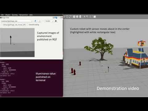
Demonstration video: Please watch the videos below to get an idea of what you can expect to achieve from this tutorial.
https://www.youtube.com/watch?v=Hqur3fG99Ug
This tutorial is prepared by Sangjun Lee (lee1424@purdue.edu) and Tamzidul Mina (tmina@purdue.edu).
The git repository is maintained by Ramviyas Parasuraman (ramviyas@purdue.edu).
We acknowledge the following sources that were used to prepare this tutorial:
-
http://www.clearpathrobotics.com/assets/guides/ros/Drive%20a%20Husky.html
-
http://www.theconstructsim.com/create-a-ros-sensor-plugin-for-gazebo/
Fundamental background of using Linux-based OS and ROS will be required to fully understand the following tutorial. For more information, please visit:
http://wiki.ros.org/ROS/Tutorials
and
We used ROS Indigo in this tutorial. But the tutorial could work even in ROS Kinetic/Lunar, although we did not validate it in Kinetic Kame.
We recommend you install ros-indigo-desktop-full so that you have all the necessary packages. The full package comes with Gazebo 2.2 as default. We recommend using a desktop PC or a laptop with Ubuntu 14.04+.
sudo apt-get install ros-indigo-desktop-full
For more help with ROS installation, follow the instructions here: https://wiki.ros.org/indigo/installation
If you do not have the gazebo_ros package, then install it using:
sudo apt-get install ros-indigo-gazebo-ros
Make sure the stand-alone Gazebo works by running in terminal:
gazebo
You will see the GUI open with an empty world. To see where you install Gazebo, and if it is in the correct location, run:
  which gzserver
  which gzclient
It should say
  /usr/bin/gzserver
  /usr/bin/gzclient
The gazebo_ros_pkgs packages are available in:
sudo apt-get install ros-indigo-gazebo-ros-pkgs ros-indigo-gazebo-ros-control
We now run Gazebo. Before doing it, be sure to always source the appropriate ROS setup file, which for Indigo is done like so:
source /opt/ros/kinetic/setup.bash
Assuming your ROS and Gazebo environment have been properly set up and built, you should now be able to run Gazebo through a simple rosrun command, after launching roscore if needed. Run roscore first:
roscore
Open another terminal and run:
rosrun gazebo_ros gazebo
The Gazebo GUI should appear with nothing inside the viewing window. To verify that the proper ROS connections are set up, view the available ROS topics:
rostopic list
You should see within the lists topics such as:
 /gazebo/link_states
 /gazebo/model_states
 /gazebo/parameter_descriptions
 /gazebo/parameter_updates
 /gazebo/set_link_state
 /gazebo/set_model_state
Open a terminal, and enter the following:
 sudo apt-get update
 sudo apt-get install ros-indigo-husky-desktop
 sudo apt-get install ros-indigo-husky-simulator
If everything looks good, then everything is good. We drive a robot now!
Run roscore first:
roscore
Open another terminal, and launch:
roslaunch husky_gazebo husky_empty_world.launch
You will see the Husky in the empty world.

We can now command the Husky to go forwards. Open a terminal window, and use the command below, copy pasting this one won’t work! You can tab complete this command by hitting the tab key after geometry_msgs/Twist:
 rostopic pub /husky_velocity_controller/cmd_vel geometry_msgs/Twist "linear:
    x: 0.5
    y: 0.0
    z: 0.0
 angular:
    x: 0.0
    y: 0.0
    z: 0.0" -r 10
In the above command, we publish to the /husky_velocity_controller/cmd_vel topic, of topic type geometry_msgs/Twist. The data we publish tells the simulated Husky to go forwards at 0.5m/s, without any rotation. You should see your Husky move forwards.
This example shows how to send a command through ROS topics between two different computers, pair up with someone else.
You need to configure ROS environment variables to properly communicate between two ROS systems.
First, check your IP address:
ifconfig
and put your IP address:
export ROS_IP=YOUR_IP
export ROS_MASTER_URI=http://YOUR_IP:11311
For example, if your IP address is 128.46.80.123
export ROS_IP=128.46.80.123
export ROS_MASTER_URI=http://128.46.80.123:11311
Then run roscore:
roscore
You will see the following messages in terminal:
SUMMARY
========

PARAMETERS
* /rosdistro: indigo
* /rosversion: 1.11.21

NODES
auto-starting new master
process[master]: started with pid [25586]
ROS_MASTER_URI=http://YOUR_IP:11311
If everything's going well, launch Gazebo
roslaunch gazebo_ros willowgarage_world.launch
You will see the Willow garage world without the robot, spawn a husky:
roslaunch husky_gazebo spawn_husky.launch
Person A is done! Now let's prepare for Person B!
To connect the ROS master, configure ROS environment variables. See your IP address:
ifconfig
and put your IP address and the master address from above:
export ROS_IP=YOUR_IP
export ROS_MASTER_URI=http://MASTER_IP:11311
For example, if your (Person B) IP address is 128.46.80.10 and the master IP is 128.46.80.123 (Person A)
export ROS_IP=128.46.80.10
export ROS_MASTER_URI=http://128.46.80.123:11311
To make sure the connection, enter:
rostopic list
You will see a bunch of topic lists such as:
/cmd_vel
/husky_velocity_controller/cmd_vel
/husky_velocity_controller/odom
....
If you've done with the previous tasks, you could move the Husky using the keyboard:
rosrun teleop_twist_keyboard teleop_twist_keyboard.py
Explore the Willow garage and change the role!
This example demonstrates how to control multiple robots simultaneously. One person runs the ROS master and Gazebo simulation and others send a command to control their robot.
Configure ROS environments like we did above and run roscore:
roscore
Launch the Gazebo:
roslaunch gazebo_ros willowgarage_world.launch
Spawn a robot at the origin (0,0):
roslaunch gazebo_plugins pioneer3dx.gazebo.launch
Spawn another robot at a different pose (0,-2) to avoid crashes:
ROBOT_INITIAL_POSE="-y -2" roslaunch husky_gazebo spawn_husky.launch
Pick one of the robots, Husky or P3dx. If you wish to control the P3dx, enter:
rosrun teleop_twist_keyboard teleop_twist_keyboard.py cmd_vel:=p3dx/cmd_vel
If you wish to control the Husky, enter:
rosrun teleop_twist_keyboard teleop_twist_keyboard.py cmd_vel:=husky_velocity_controller/cmd_vel
Compete who escape the Willow garage first!
We will design a simple feedback controller to drive a robot to reach the goal location. In general, autonomous navigation represents a multi-layered embedded system that has the following abilities:
-
to generate an optimal path without collisions,
-
to follow the path generated with desired pose and location,
-
to compute an alternative path if necessary.
In this tutorial, we will design a simple controller that receives the desired destination from the user and publishes command messages to the robot.
Go to the gazebo_tutorial ROS package in this repository and download nre_simhuskycontrol.py to your device.
This controller allows you to adjust controller parameters, proportional gains, and goals. By tuning those variables, you will be able to see better control performance. The controller works in the following algorithm.
-
Calculate difference between current and desired locations. From line 32:
distance = sqrt((pose[0]-goal[0])**2+(pose[1]-goal[1])**2) -
If distance is below a threshold, stop the robot. OR if distance is above the threshold, set yaw angle to orient robot toward desired location, and drive towards it. From line 33:
if (distance > distThresh):
      v = vconst
      desireYaw = atan2(goal[1]-pose[1],goal[0]-pose[0])
      u = desireYaw-theta
      bound = atan2(sin(u),cos(u))
      w = min(0.5 , max(-0.5, wgain*bound))
The algorithm is illustrated in the following image.

Run roscore first:
roscore
Open another terminal, and launch:
roslaunch husky_gazebo husky_empty_world.launch
You will see the Husky in the empty world. To monitor the real-time position data, run:
rostopic echo /odometery/filtered
Go to the folder that includes nre_simhuskycontrol.py and run the controller:
python nre_simhuskycontrol.py
The Husky will not move because the goal is now (0,0). Change the goal in the script and rerun nre_simhuskycontrol.py. For example, the robot will stop as soon as it gets close to the destination at (10,10). You could see your robot has stopped at the destination and the odometry data is close to (10,10) within the distThresh that you defined.
Let's run the controller again with different parameters (wgain, vconst, distThresh).


In the previous section, we learned how to run and control an existing robot on Gazebo. If our work requires a custom robot to be built, this section provides introductory instructions on how to get started with a basic setup. The Model Editor in later versions of Gazebo lets us construct simple models right in the Graphical User Interface (GUI). But for more complex models, you'll need to learn how to write SDF files.
This tutorial demonstrates Gazebo's basic model management, and exercises familiarity with basic model representation inside the model database by taking the user through the process of creating a .sdf file for a two-wheeled mobile robot that uses:
- a differential drive mechanism for movement
- a mesh as visual
- a custom light sensor based on camera for reading the environment
When creating our own model, we must adhere to the formatting rules for the Gazebo Model Database directory structure. Therefore, it is recommended that you familiarize yourself with the Model Database documentation and model description formats at SDF reference.
-
Create a model directory where we call our robot '2wd_mr', short for 2 wheels drive mobile robot:
mkdir -p ~/.gazebo/models/2wd_mr -
Create a model config file:
gedit ~/.gazebo/models/2wd_mr/model.config -
Paste in the following contents:
<?xml version="1.0"?> <model> <name>2wd_mr</name> <version>1.0</version> <sdf version='1.4'>model.sdf</sdf> <author> <name>My Name</name> <email>me@my.email</email> </author> <description> My awesome robot with an awesome sensor. </description> </model> -
Create a
model.sdffile:gedit ~/.gazebo/models/2wd_mr/model.sdf -
Paste in the following:
<?xml version='1.0'?>
<sdf version='1.4'>
  <model name="2wd_mr">
  </model>
</sdf>
At this point, we have the basic content for a model. The model.config file describes the robot with some extra metadata. The model.sdf file contains the necessary tags to instantiate a model named 2wd_mr using Gazebo linked against SDF version 1.4.
Our first robot will have a rectangular base with two wheels on the side and a caster wheel at the rear. First, we lay out the basic shapes of the model. To do this we will make our model static, which means it will be ignored by the physics engine. As a result, the model will stay in one place and allow us to properly align all the components.
Open the ~/.gazebo/models/2wd_mr/model.sdf file.
- Make the model static by adding a
<static>true</static>element:
    <?xml version='1.0'?>
    <sdf version='1.4'>
      <model name="2wd_mr">
<static>true</static>
      </model>
    </sdf>
- Add the rectangular base of size
0.4 x 0.2 x 0.1meters:
    <?xml version='1.0'?>
      <sdf version='1.4'>
        <model name="2wd_mr">
        <static>true</static>
          <link name='chassis'>
            <pose>0 0 .1 0 0 0</pose>

            <collision name='collision'>
              <geometry>
                <box>
                  <size>.4 .2 .1</size>
                </box>
              </geometry>
            </collision>

            <visual name='visual'>
              <geometry>
                <box>
                  <size>.4 .2 .1</size>
                </box>
              </geometry>
            </visual>
          </link>
      </model>
    </sdf>
The collision element specifies the shape used by the collision detection engine. The visual element specifies the shape used by the rendering engine.
-
Try out your model by running gazebo, and importing your model through the Insert Model interface on the GUI.
gazeboYou should see a white box floating .1 meters above the ground plane.
-
Now we can add a caster to the robot. The caster is a sphere with no friction. This kind of caster is better than adding a wheel with a joint since it places fewer constraints on the physics engine.
    <?xml version='1.0'?>
    <sdf version='1.4'>
      <model name="2wd_mr">
        <static>true</static>
        <link name='chassis'>
          <pose>0 0 .1 0 0 0</pose>
          <collision name='collision'>
            <geometry>
              <box>
                <size>.4 .2 .1</size>
              </box>
            </geometry>
          </collision>

          <visual name='visual'>
            <geometry>
              <box>
                <size>.4 .2 .1</size>
              </box>
            </geometry>
          </visual>
          <collision name='caster_collision'>
            <pose>-0.15 0 -0.05 0 0 0</pose>
            <geometry>
                <sphere>
                <radius>.05</radius>
              </sphere>
            </geometry>

            <surface>
              <friction>
                <ode>
                  <mu>0</mu>
                  <mu2>0</mu2>
                  <slip1>1.0</slip1>
                  <slip2>1.0</slip2>
                </ode>
              </friction>
            </surface>
          </collision>

          <visual name='caster_visual'>
            <pose>-0.15 0 -0.05 0 0 0</pose>
            <geometry>
              <sphere>
                <radius>.05</radius>
              </sphere>
            </geometry>
          </visual>
        </link>
      </model>
    </sdf>
Try out your model to make sure the caster appears at the end of the robot (you don't need to restart Gazebo; it will reload your modified model from disk each time you insert it):
- Add a left wheel:
    <?xml version='1.0'?>
    <sdf version='1.4'>
      <model name="2wd_mr">
        <static>true</static>
        <link name='chassis'>
          <pose>0 0 .1 0 0 0</pose>
          <collision name='collision'>
            <geometry>
              <box>
                <size>.4 .2 .1</size>
              </box>
            </geometry>
          </collision>

          <visual name='visual'>
            <geometry>
              <box>
                <size>.4 .2 .1</size>
              </box>
            </geometry>
          </visual>

          <collision name='caster_collision'>
            <pose>-0.15 0 -0.05 0 0 0</pose>
            <geometry>
              <sphere>
              <radius>.05</radius>
            </sphere>
          </geometry>

          <surface>
            <friction>
              <ode>
                <mu>0</mu>
                <mu2>0</mu2>
                <slip1>1.0</slip1>
                <slip2>1.0</slip2>
              </ode>
            </friction>
          </surface>
        </collision>

        <visual name='caster_visual'>
          <pose>-0.15 0 -0.05 0 0 0</pose>
          <geometry>
            <sphere>
              <radius>.05</radius>
            </sphere>
          </geometry>
        </visual>
      </link>
      <link name="left_wheel">
        <pose>0.1 0.13 0.1 0 1.5707 1.5707</pose>
        <collision name="collision">
          <geometry>
            <cylinder>
              <radius>.1</radius>
              <length>.05</length>
            </cylinder>
          </geometry>
        </collision>
        <visual name="visual">
          <geometry>
            <cylinder>
              <radius>.1</radius>
              <length>.05</length>
            </cylinder>
          </geometry>
        </visual>
      </link>
      </model>
    </sdf>
Run Gazebo, insert your robot model and make sure the wheel has appeared and is in the correct location.
- We can make a right wheel by copying the left wheel, and adjusting the wheel link's pose:
    <?xml version='1.0'?>
    <sdf version='1.4'>
      <model name="2wd_mr">
        <static>true</static>
        <link name='chassis'>
          <pose>0 0 .1 0 0 0</pose>
          <collision name='collision'>
            <geometry>
              <box>
                <size>.4 .2 .1</size>
              </box>
            </geometry>
          </collision>

          <visual name='visual'>
            <geometry>
              <box>
                <size>.4 .2 .1</size>
              </box>
            </geometry>
          </visual>

          <collision name='caster_collision'>
            <pose>-0.15 0 -0.05 0 0 0</pose>
            <geometry>
              <sphere>
              <radius>.05</radius>
            </sphere>
          </geometry>

          <surface>
            <friction>
              <ode>
                <mu>0</mu>
                <mu2>0</mu2>
                <slip1>1.0</slip1>
                <slip2>1.0</slip2>
              </ode>
            </friction>
          </surface>
        </collision>

        <visual name='caster_visual'>
          <pose>-0.15 0 -0.05 0 0 0</pose>
          <geometry>
            <sphere>
              <radius>.05</radius>
            </sphere>
          </geometry>
        </visual>
      </link>
      <link name="left_wheel">
        <pose>0.1 0.13 0.1 0 1.5707 1.5707</pose>
        <collision name="collision">
          <geometry>
            <cylinder>
              <radius>.1</radius>
              <length>.05</length>
            </cylinder>
          </geometry>
        </collision>
        <visual name="visual">
          <geometry>
            <cylinder>
              <radius>.1</radius>
              <length>.05</length>
            </cylinder>
          </geometry>
        </visual>
      </link>
      <link name="right_wheel">
        <pose>0.1 -0.13 0.1 0 1.5707 1.5707</pose>
        <collision name="collision">
          <geometry>
            <cylinder>
              <radius>.1</radius>
              <length>.05</length>
            </cylinder>
          </geometry>
        </collision>
        <visual name="visual">
          <geometry>
            <cylinder>
              <radius>.1</radius>
              <length>.05</length>
            </cylinder>
          </geometry>
        </visual>
      </link>
      </model>
    </sdf>
At this point, the robot should have a chassis with a caster and two wheels as shown below.

- Make the model dynamic by setting
<static>to false, and add two hinge joints for the left and right wheels.
    <?xml version='1.0'?>
    <sdf version='1.4'>
      <model name="2wd_mr">
<static>false</static>
        <link name='chassis'>
          <pose>0 0 .1 0 0 0</pose>
          <collision name='collision'>
            <geometry>
              <box>
                <size>.4 .2 .1</size>
              </box>
            </geometry>
          </collision>

          <visual name='visual'>
            <geometry>
              <box>
                <size>.4 .2 .1</size>
              </box>
            </geometry>
          </visual>

          <collision name='caster_collision'>
            <pose>-0.15 0 -0.05 0 0 0</pose>
            <geometry>
              <sphere>
              <radius>.05</radius>
            </sphere>
          </geometry>

          <surface>
            <friction>
              <ode>
                <mu>0</mu>
                <mu2>0</mu2>
                <slip1>1.0</slip1>
                <slip2>1.0</slip2>
              </ode>
            </friction>
          </surface>
        </collision>

        <visual name='caster_visual'>
          <pose>-0.15 0 -0.05 0 0 0</pose>
          <geometry>
            <sphere>
              <radius>.05</radius>
            </sphere>
          </geometry>
        </visual>
      </link>
      <link name="left_wheel">
        <pose>0.1 0.13 0.1 0 1.5707 1.5707</pose>
        <collision name="collision">
          <geometry>
            <cylinder>
              <radius>.1</radius>
              <length>.05</length>
            </cylinder>
          </geometry>
        </collision>
        <visual name="visual">
          <geometry>
            <cylinder>
              <radius>.1</radius>
              <length>.05</length>
            </cylinder>
          </geometry>
        </visual>
      </link>

      <link name="right_wheel">
        <pose>0.1 -0.13 0.1 0 1.5707 1.5707</pose>
        <collision name="collision">
          <geometry>
            <cylinder>
              <radius>.1</radius>
              <length>.05</length>
            </cylinder>
          </geometry>
        </collision>
        <visual name="visual">
          <geometry>
            <cylinder>
              <radius>.1</radius>
              <length>.05</length>
            </cylinder>
          </geometry>
        </visual>
      </link>
      <joint type="revolute" name="left_wheel_hinge">
        <pose>0 0 -0.03 0 0 0</pose>
        <child>left_wheel</child>
        <parent>chassis</parent>
        <axis>
          <xyz>0 1 0</xyz>
        </axis>
      </joint>

      <joint type="revolute" name="right_wheel_hinge">
        <pose>0 0 0.03 0 0 0</pose>
        <child>right_wheel</child>
        <parent>chassis</parent>
        <axis>
          <xyz>0 1 0</xyz>
        </axis>
      </joint>
      </model>
    </sdf>
The two joints rotate about the y-axis <xyz>0 1 0</xyz>, and connect each wheel to the chassis.
-
Start gazebo and spawn your robot model. Select your robot model and click on the dots to the right of the screen and drag them to the left to open the hidden panel.
-
Under the
Forcetab, increase the force applied to each joint to about 0.1N-m. The robot should start to move!
Congrats! you now have a basic mobile robot.
Meshes can add realism to a model both visually and for sensors. This section demonstrates how the user can use custom meshes to define how their model will appear in the simulation. The most common use case for a mesh is to create a realistic looking visual.
-
Navigate to the
2wd_mrdirectorycd ~/.gazebo/models/2wd_mr -
Open the
model.sdffile using your favorite editorgedit ~/.gazebo/models/2wd_mr/model.sdf -
To add a mesh to the chassis visual, find
name=visual, which looks like:<visual name='visual'> <geometry> <box> <size>.4 .2 .1</size> </box> </geometry> </visual> -
A mesh can come from a file on disk, or from another model. In this example, we'll use a mesh from the pioneer2dx model. Change the visual element to the following (but keep the rest of the file intact):
<visual name='visual'> <geometry> <mesh> <uri>model://pioneer2dx/meshes/chassis.dae</uri> </mesh> </geometry> </visual> -
Look in your locally cached model database to see if you have the
pioneer2dxmodel referenced by above<mesh>block:ls -l ~/.gazebo/models/pioneer2dx/meshes/chassis.dae
If the mesh file does not exist, make Gazebo pull the model from the Model Database by spawning the Pioneer 2DX model at least once in Gazebo (under Insert->http://gazebosim.org/models).
Or manually download the model files to your local cache:
    cd ~/.gazebo/models
    wget -q -R *index.html*,*.tar.gz --no-parent -r -x -nH http://models.gazebosim.org/pioneer2dx/
-
In Gazebo, drag the
2wd_mrmodel in the world. The visual for the chassis will look like a pioneer2dx. -
If the chassis is obviously too big for our robot, we need to scale the visual and change pose. Modify the visual to have a scaling factor:
    <visual name='visual'>
      <geometry>
        <mesh>
          <uri>model://pioneer2dx/meshes/chassis.dae</uri>
<scale>0.9 0.5 0.5</scale>
        </mesh>
      </geometry>
    </visual>
And raise the chassis up a little by specifying a pose for the visual:
<visual name='visual'>
<pose>0 0 0.05 0 0 0</pose>
      <geometry>
        <mesh>
          <uri>model://pioneer2dx/meshes/chassis.dae</uri>
          <scale>0.9 0.5 0.5</scale>
        </mesh>
      </geometry>
    </visual>
The figures below illustrate the changes.

Note that at this point we have simply modified the <visual> elements of the robot, so the robot will look like a scaled-down version of the Pioneer 2DX model through the GUI and to GPU based sensors such as camera, a depth camera, and GPU Lasers. Since we did not modify the <collision> elements in this model, the box geometry will still be used by the physics engine for collision dynamics and by CPU based ray sensors.
Our goal is to mount a custom sensor on top of our robot and publish the sensor readings on a rostopic. To do that, we first create a ROS plugin for our camera-based light sensor.
In this section, we cover how to create a custom light sensor and its plugin to publish sensor readings on a ROS topic. The idea is that the sensor can be mounted on the previously built mobile robot to monitor the environment(world) created on gazebo with the robot.
We build our simple light detector sensor based on a camera. We use a camera to capture an image and then use the image to calculate the illuminance of the image. The illuminance value is then published through a ROS topic.
The tutorial is divided into two sections.
- Create the light sensor plugin
- Test that it works
The next section creates the light sensor model and mounts it on our previously built robot.
-
Create e ROS package for the plugin in your catkin workspace that will allow compiling of the plugin.
> cd ~/catkin_ws/src > catkin_create_pkg gazebo_light_sensor_plugin gazebo_ros gazebo_plugins roscpp -
Since we are using a camera to capture the light, we are going to create a plugin class that inherits from the CameraPlugin. The code that follows has been created taking as guideline the code of the authentic gazebo ROS camera plugin
Navigate to your package and create a file called light_sensor_plugin.h in directory /include/gazebo_light_sensor_plugin/. Paste the following code:
    #ifndef GAZEBO_ROS_LIGHT_SENSOR_HH
    #define GAZEBO_ROS_LIGHT_SENSOR_HH

    #include <string>

    // library for processing camera data for gazebo / ros conversions
    #include <gazebo/plugins/CameraPlugin.hh>

    #include <gazebo_plugins/gazebo_ros_camera_utils.h>

    namespace gazebo
    {
      class GazeboRosLight : public CameraPlugin, GazeboRosCameraUtils
      {
        /// \brief Constructor
        /// \param parent The parent entity, must be a Model or a Sensor
        public: GazeboRosLight();

        /// \brief Destructor
        public: ~GazeboRosLight();

        /// \brief Load the plugin
        /// \param take in SDF root element
        public: void Load(sensors::SensorPtr _parent, sdf::ElementPtr _sdf);

        /// \brief Update the controller
        protected: virtual void OnNewFrame(const unsigned char *_image,
        unsigned int _width, unsigned int _height,
        unsigned int _depth, const std::string &_format);

        ros::NodeHandle _nh;
        ros::Publisher _sensorPublisher;

        double _fov;
        double _range;
      };
    }
    #endif
The above code includes a node handler to connect to the roscore. It also defines a publisher that will publish messages containing the illuminance value. Two parameters have been defined: fov (field of view) and range. At present only Field of View (FOV) is used to indicate the number of pixels around the center of the image that will be taken into account to calculate the illuminance.
-
Create a file named light_sensor_plugin.cpp containing the following code in the src directory of your package:
#include <gazebo/common/Plugin.hh>
#include <ros/ros.h>
#include "gazebo_light_sensor_plugin/light_sensor_plugin.h"

#include "gazebo_plugins/gazebo_ros_camera.h"

#include <string>

#include <gazebo/sensors/Sensor.hh>
#include <gazebo/sensors/CameraSensor.hh>
#include <gazebo/sensors/SensorTypes.hh>

#include <sensor_msgs/Illuminance.h>

namespace gazebo
{
  // Register this plugin with the simulator
  GZ_REGISTER_SENSOR_PLUGIN(GazeboRosLight)

  ////////////////////////////////////////////////////////////////////////////////
  // Constructor
  GazeboRosLight::GazeboRosLight():
  _nh("light_sensor_plugin"),
  _fov(6),
  _range(10)
  {
    _sensorPublisher = _nh.advertise<sensor_msgs::Illuminance>("lightSensor", 1);
  }

  ////////////////////////////////////////////////////////////////////////////////
  // Destructor
  GazeboRosLight::~GazeboRosLight()
  {
    ROS_DEBUG_STREAM_NAMED("camera","Unloaded");
  }

  void GazeboRosLight::Load(sensors::SensorPtr _parent, sdf::ElementPtr _sdf)
  {
    // Make sure the ROS node for Gazebo has already been initialized
    if (!ros::isInitialized())
    {
      ROS_FATAL_STREAM("A ROS node for Gazebo has not been initialized, unable to load plugin. "
        << "Load the Gazebo system plugin 'libgazebo_ros_api_plugin.so' in the gazebo_ros package)");
      return;
    }

    CameraPlugin::Load(_parent, _sdf);
    // copying from CameraPlugin into GazeboRosCameraUtils
    this->parentSensor_ = this->parentSensor;
    this->width_ = this->width;
    this->height_ = this->height;
    this->depth_ = this->depth;
    this->format_ = this->format;
    this->camera_ = this->camera;

    GazeboRosCameraUtils::Load(_parent, _sdf);
  }

  ////////////////////////////////////////////////////////////////////////////////
  // Update the controller
  void GazeboRosLight::OnNewFrame(const unsigned char *_image,
    unsigned int _width, unsigned int _height, unsigned int _depth,
    const std::string &_format)
  {
    static int seq=0;

    this->sensor_update_time_ = this->parentSensor_->GetLastUpdateTime();

    if (!this->parentSensor->IsActive())
    {
      if ((*this->image_connect_count_) > 0)
      // do this first so there's chance for sensor to run once after activated
        this->parentSensor->SetActive(true);
    }
    else
    {
      if ((*this->image_connect_count_) > 0)
      {
        common::Time cur_time = this->world_->GetSimTime();
        if (cur_time - this->last_update_time_ >= this->update_period_)
        {
          this->PutCameraData(_image);
          this->PublishCameraInfo();
          this->last_update_time_ = cur_time;

          sensor_msgs::Illuminance msg;
          msg.header.stamp = ros::Time::now();
          msg.header.frame_id = "";
          msg.header.seq = seq;

          int startingPix = _width * ( (int)(_height/2) - (int)( _fov/2)) - (int)(_fov/2);

          double illum = 0;
          for (int i=0; i<_fov ; ++i)
          {
            int index = startingPix + i*_width;
            for (int j=0; j<_fov ; ++j)
              illum += _image[index+j];
          }

          msg.illuminance = illum/(_fov*_fov);
          msg.variance = 0.0;

          _sensorPublisher.publish(msg);

          seq++;
        }
      }
    }
  }
}
The above code calculates the illuminance in a very simple way (calculates the average value). It adds the values of all the pixels in the FOV of the camera and then divides by the total number of pixels.
-
Substitute the code of the automatically created CMakeLists.txt by the code below:
cmake_minimum_required(VERSION 2.8.3) project(gazebo_light_sensor_plugin) find_package(catkin REQUIRED COMPONENTS gazebo_plugins gazebo_ros roscpp ) find_package (gazebo REQUIRED) catkin_package( INCLUDE_DIRS include CATKIN_DEPENDS gazebo_plugins gazebo_ros roscpp ) ########### ## Build ## ########### set(CMAKE_CXX_FLAGS "-std=c++11 ${CMAKE_CXX_FLAGS}") link_directories(${GAZEBO_LIBRARY_DIRS}) include_directories(include) include_directories( ${catkin_INCLUDE_DIRS} ${Boost_INCLUDE_DIR} ${GAZEBO_INCLUDE_DIRS} ) add_library(${PROJECT_NAME} src/light_sensor_plugin.cpp) ## Specify libraries to link a library or executable target against target_link_libraries( ${PROJECT_NAME} ${catkin_LIBRARIES} ${GAZEBO_LIBRARIES} CameraPlugin ) -
Update the package.xml file by including the following line in your package.xml between the tags
_<export></export>_<gazebo_ros plugin_path="${prefix}/lib" gazebo_media_path="${prefix}" />
-
Compile your plugin using the commands below. Compilation should generate the library containing the plugin inside our building directory.
 > roscd
 > cd ..
 > catkin_make
-
We first create a world file that includes the plugin. Create a worlds directory inside your plugin package, and save the following code in a file entitled light.world. This world file just loads the camera with its plugin.
<?xml version="1.0" ?> <sdf version="1.4"> <world name="default"> <include> <uri>model://ground_plane</uri> </include> <include> <uri>model://sun</uri> </include> <!-- reference to your plugin --> <model name='camera'> <pose>0 -1 0.05 0 -0 0</pose> <link name='link'> <inertial> <mass>0.1</mass> <inertia> <ixx>1</ixx> <ixy>0</ixy> <ixz>0</ixz> <iyy>1</iyy> <iyz>0</iyz> <izz>1</izz> </inertia> </inertial> <collision name='collision'> <geometry> <box> <size>0.1 0.1 0.1</size> </box> </geometry> <max_contacts>10</max_contacts> <surface> <contact> <ode/> </contact> <bounce/> <friction> <ode/> </friction> </surface> </collision> <visual name='visual'> <geometry> <box> <size>0.1 0.1 0.1</size> </box> </geometry> </visual> <sensor name='camera' type='camera'> <camera name='__default__'> <horizontal_fov>1.047</horizontal_fov> <image> <width>320</width> <height>240</height> </image> <clip> <near>0.1</near> <far>100</far> </clip> </camera> <plugin name="gazebo_light_sensor_plugin" filename="libgazebo_light_sensor_plugin.so"> <cameraName>camera</cameraName> <alwaysOn>true</alwaysOn> <updateRate>10</updateRate> <imageTopicName>rgb/image_raw</imageTopicName> <depthImageTopicName>depth/image_raw</depthImageTopicName> <pointCloudTopicName>depth/points</pointCloudTopicName> <cameraInfoTopicName>rgb/camera_info</cameraInfoTopicName> <depthImageCameraInfoTopicName>depth/camera_info</depthImageCameraInfoTopicName> <frameName>camera_depth_optical_frame</frameName> <baseline>0.1</baseline> <distortion_k1>0.0</distortion_k1> <distortion_k2>0.0</distortion_k2> <distortion_k3>0.0</distortion_k3> <distortion_t1>0.0</distortion_t1> <distortion_t2>0.0</distortion_t2> <pointCloudCutoff>0.4</pointCloudCutoff> <robotNamespace>/</robotNamespace> </plugin> </sensor> <self_collide>0</self_collide> <kinematic>0</kinematic> <gravity>1</gravity> </link> </model> </world> </sdf> -
Next, we create a launch file for the plugin. A launch file is useful when you want to start/launch many nodes at once without any need to do "rosrun for every node". In the package, create a directory by the name 'launch' and create a main.launch file.
<launch> <!-- We resume the logic in empty_world.launch, changing only the name of the world to be launched --> <include file="$(find gazebo_ros)/launch/empty_world.launch"> <arg name="verbose" value="true"/> <arg name="world_name" value="$(find gazebo_light_sensor_plugin)/worlds/light.world"/> <!-- more default parameters can be changed here --> </include> </launch> -
To run the light sensor plugin on Gazebo from ROS, run ROSCORE and launch the world. Be sure that the GAZEBO_PLUGIN_PATH environment var includes the path to the new plugin.
Now execute the following command:
> roslaunch gazebo_light_sensor_plugin main.launch
Add a few objects on the world in front of the camera. You can see what the camera is observing by running the following command:
> rosrun image_view image_view image:=/camera/rgb/image_raw
After running that command, a small window will appear in your screen showing what the camera is capturing.

Next, we check the calculated illuminance by watching the published topic (/light_sensor_plugin/lightSensor). Type the following command to see the calculated illuminance value from the image:
> rostopic echo /light_sensor_plugin/lightSensor
You should see the topic messages being published on screen:

In this section, we mount the light sensor on the custom mobile robot (sdf file) created previously. Let the mobile robot move about; watch the images being captured and the calculated illuminance values published in real time.
-
Create a model directory for the light sensor:
mkdir -p ~/.gazebo/models/light_sensor -
Create a model config file similar to what we did for our robot:
gedit ~/.gazebo/models/light_sensor/model.config -
Paste in the following contents:
<?xml version="1.0"?> <model> <name>light_sensor</name> <version>1.0</version> <sdf version="1.4">model.sdf</sdf> <author> <name>My Name</name> <email>me@my.email</email> </author> <description> light sensor model based on camera </description> </model> -
Create a
model.sdffile:gedit ~/.gazebo/models/light_sensor/model.sdf -
Paste in the following:
<?xml version="1.0" ?>
<sdf version="1.4">
<model name='light_sensor'>
    <pose>0 -1 0.05 0 -0 0</pose>
    <link name='link'>
    <inertial>
      <mass>0.1</mass>
      <inertia>
        <ixx>1</ixx>
        <ixy>0</ixy>
        <ixz>0</ixz>
        <iyy>1</iyy>
        <iyz>0</iyz>
        <izz>1</izz>
      </inertia>
    </inertial>
   <collision name='collision'>
    <geometry>
     <box>
        <size>0.1 0.1 0.1</size>
     </box>
    </geometry>
   <max_contacts>10</max_contacts>
    <surface>
     <contact>
       <ode/>
     </contact>
     <bounce/>
     <friction>
       <ode/>
     </friction>
    </surface>
   </collision>
   <visual name='visual'>
    <geometry>
      <box>
       <size>0.1 0.1 0.1</size>
      </box>
    </geometry>
   </visual>
   <sensor name='camera' type='camera'>
   <camera name='__default__'>
     <horizontal_fov>1.047</horizontal_fov>
     <image>
       <width>320</width>
       <height>240</height>
     </image>
     <clip>
       <near>0.1</near>
       <far>100</far>
     </clip>
   </camera>
   <plugin name="gazebo_light_sensor_plugin" filename="libgazebo_light_sensor_plugin.so">
     <cameraName>camera</cameraName>
     <alwaysOn>true</alwaysOn>
     <updateRate>10</updateRate>
     <imageTopicName>rgb/image_raw</imageTopicName>
     <depthImageTopicName>depth/image_raw</depthImageTopicName>
     <pointCloudTopicName>depth/points</pointCloudTopicName>
     <cameraInfoTopicName>rgb/camera_info</cameraInfoTopicName>
     <depthImageCameraInfoTopicName>depth/camera_info</depthImageCameraInfoTopicName>
     <frameName>camera_depth_optical_frame</frameName>
     <baseline>0.1</baseline>
     <distortion_k1>0.0</distortion_k1>
     <distortion_k2>0.0</distortion_k2>
     <distortion_k3>0.0</distortion_k3>
     <distortion_t1>0.0</distortion_t1>
     <distortion_t2>0.0</distortion_t2>
     <pointCloudCutoff>0.4</pointCloudCutoff>
     <robotNamespace>/</robotNamespace>
    </plugin>
  </sensor>
  <self_collide>0</self_collide>
  <kinematic>0</kinematic>
  <gravity>1</gravity>
  </link>
 </model>
</sdf>
The above code is adapted from the light.world file we created in the previous section to test our light sensor. Instead of loading the model as a rectangular box on an empty plane, we only define the box here.
Once the light_sensor model has been created, we place it on top of our custom robot model. Open the 'model.sdf' file for our previously built custom robot '2wd_mr' and add the following lines.
    <?xml version='1.0'?>
    <sdf version='1.4'>
      <model name="2wd_mr">

       <static>false</static>

        <link name='chassis'>
          <pose>0 0 .1 0 0 0</pose>
          <collision name='collision'>
            <geometry>
              <box>
                <size>.4 .2 .1</size>
              </box>
            </geometry>
          </collision>

          <visual name='visual'>
            <geometry>
              <box>
                <size>.4 .2 .1</size>
              </box>
            </geometry>
          </visual>

          <collision name='caster_collision'>
            <pose>-0.15 0 -0.05 0 0 0</pose>
            <geometry>
              <sphere>
              <radius>.05</radius>
            </sphere>
          </geometry>

          <surface>
            <friction>
              <ode>
                <mu>0</mu>
                <mu2>0</mu2>
                <slip1>1.0</slip1>
                <slip2>1.0</slip2>
              </ode>
            </friction>
          </surface>
        </collision>

        <visual name='caster_visual'>
          <pose>-0.15 0 -0.05 0 0 0</pose>
          <geometry>
            <sphere>
              <radius>.05</radius>
            </sphere>
          </geometry>
        </visual>
      </link>
      <link name="left_wheel">
        <pose>0.1 0.13 0.1 0 1.5707 1.5707</pose>
        <collision name="collision">
          <geometry>
            <cylinder>
              <radius>.1</radius>
              <length>.05</length>
            </cylinder>
          </geometry>
        </collision>
        <visual name="visual">
          <geometry>
            <cylinder>
              <radius>.1</radius>
              <length>.05</length>
            </cylinder>
          </geometry>
        </visual>
      </link>

      <link name="right_wheel">
        <pose>0.1 -0.13 0.1 0 1.5707 1.5707</pose>
        <collision name="collision">
          <geometry>
            <cylinder>
              <radius>.1</radius>
              <length>.05</length>
            </cylinder>
          </geometry>
        </collision>
        <visual name="visual">
          <geometry>
            <cylinder>
              <radius>.1</radius>
              <length>.05</length>
            </cylinder>
          </geometry>
        </visual>
      </link>

     <joint type="revolute" name="left_wheel_hinge">
       <pose>0 0 -0.03 0 0 0</pose>
       <child>left_wheel</child>
       <parent>chassis</parent>
       <axis>
         <xyz>0 1 0</xyz>
       </axis>
     </joint>

     <joint type="revolute" name="right_wheel_hinge">
       <pose>0 0 0.03 0 0 0</pose>
       <child>right_wheel</child>
       <parent>chassis</parent>
       <axis>
        <xyz>0 1 0</xyz>
       </axis>
     </joint>
        <include>
  	     <uri>model://light_sensor</uri>
  	     <pose>0.2 0 0.2 0 0 0</pose>
	    </include>
       <joint name="sensor_joint" type="revolute">
	        <child>light_sensor::link</child>
        <parent>chassis</parent>
        <axis>
         <xyz>0 0 1</xyz>
         <limit>
          <upper>0</upper>
          <lower>0</lower>
         </limit>
        </axis>
      </joint>
      </model>
    </sdf>
Once the model has been updated, we are ready to run our robot and capture the environment with our custom sensor. Call roslaunch with an empty world in Gazebo.
roslaunch gazebo_ros empty_world.launch
Spawn a copy of the custom robot model on the empty world. The robot model previously built now shows the rectangular box on top which is our custom sensor. You can adjust its pose as necessary to align the sensor properly. The completed robot with the sensor is shown below.

Place random objects around the robot for monitoring.

The model at the moment is publishing on rostopic and the topics can be listed by the following command.
rostopic list
If everything went well, the result should show up as follows.

Call 'rqt' and select the raw image topic from the drop-down menu to view the sensor captured frames.

Use the following command to publish the illuminance value calculated on each frame.
rostopic echo /light_sensor_plugin/lightSensor

Allow the robot to move around by changing the wheel joint forces as shown previously. As the robot moves along, it now captures the video using the custom built sensor and calculates the illuminance value, published on a ROS node.
A demo video of the outcome is available below.
In this tutorial, we presented an introduction to using Gazebo simulation for robot navigation and control. Also, we saw how to create a custom robot with a custom sensor and able to publish the sensor outputs on ROS topics.
The tutorials are summarized and adapted from the sources mentioned in Section 2. We hope, this tutorial will be helpful to anyone starting out with Gazebo and ROS.