Assembly Manual
(major revision August 2018; minor corrections Feb 2019)
For main board version 1.1r5a
F1. Introduction
F2. Changes since last version
F3. Before You StartF3.1. Warnings
F3.2. Tools You'll Need
1.1. Small Components
1.1.1. Resistors
1.1.2. Other small components
1.1.3. Switches
1.1.4. Piezo buzzer
1.1.5. iRover Connector (aka Triple Connector)1.2. Daughter boards
1.2.1. Open Log
1.2.2. Arduino FIO
1.2.3. GPS module
1.2.4. Display module1.3. Power On Test
1.4. Front Plate
1.5. Battery
2. MIDDLE PLATE
2.2.1 Sensor Screen Attachment
2.3. Bottom Plate
3. Pelican Case
4.1. Counter Function
4.2. SD Card
4.3. GPS Lock
4.4. Battery
5. Mounting and Use
6. Notes
This manual provides instructions for assembling the Safecast bGeigie Nano Mobile Radiation Monitoring Device. We're happy to be able to provide this high-performance Geiger counter with GPS logging and memory, which has been developed and field-tested by hundreds of Safecast volunteers and has revolutionized citizen-science-based radiation surveys.
The kit is an excellent tool for DIY learning. Assembly can take as little as 3-4 hours, depending on your level of skill and experience with electronics. Beginners should allow approximately eight hours.
For Nano Support: catch-all landing page http://nano.safecast.org/; these community-edited nano wiki pages; the links on the home page of Safecast website http://blog.safecast.org/; the Safecast Devices Discussions and Support group. Contact info@safecast.org.
You can purchase a bGeigie nano kit at kithub.cc.
This version of the manual reflects changes appropriate for Nano main board version 1.1r5a. The version number of the board is printed on the reverse side.

Caption: Main Board (PCB) reverse side with board version number highlighted.
Overall, the assembly process is very similar previous versions, but the order of some assembly steps has been changed based on experience teaching the build. In addition, attention is called to components which may be slightly different than those in the original bGeigie nano kit.

Note that the LND_7317 pancake sensor is very delicate. It has a thin mica covering on one face, inside of which there is a partial vacuum. The mica is easily punctured. Should this occur, it will damage the tube irreparably. We recommend that you leave the pancake sensor in the box until you're ready to attach it.
IMPORTANT: Some bGeigie Nano kits are provided with a protective mesh screen already attached. Check the sensor in your kit now before you begin building. If the protective mesh screen has not yet been attached, please complete section 2.2.1 Sensor Screen Attachment below before continuing.
As with any project, take the time to prepare by gathering the necessary tools, clearing space, reading the manual, and turning off distractions before you start.
- The temperature of the soldering iron should be about 200-350 degrees Celsius (400-650 degrees Fahrenheit).
- Smoke from solder is dangerous for your health, so work in a well-ventilated area.
- Wear safety glasses when cutting off leads.
- Do not puncture the Li-Po battery.
- Be gentle with the kit. Some of the components are fragile. For example, it's possible to inadvertently break the wire leads from the battery.
- Soldering iron or gun
- Solder (60/40)
- Screwdriver (small Phillips-head/plus)
- Needle-nosed pliers
- Nippers (for cutting component leads)
The following may be necessary for addition: *Clear acrylic nail polish (aka "nail top coat," without glitter) — To use as adhesive for attaching the protective screen to the sensor if necessary (see step 2.2.1 Sensor Screen Attachment)

The parts come in several smaller bags.
— Identify, count, and check the parts against the Parts List wiki page at https://github.com/Safecast/bGeigieNanoKit/wiki/Parts-List — You can also check them against the placement diagrams in this manual and relevant photos. — If parts are missing or damaged, please contact us at info@safecast.org.[link] — Carefully open the sensor box and check to see if the protective screen is attached. If not, go to 2.2.1 Sensor Screen Attachment.

Caption: Main board (PCP) version 1.1r.5a, front side.
Nearly all of the components attach to the main board (PCB). Consult the Large Parts, Small Parts, and Back Parts placement diagrams below for help with placing parts.While we suggest starting with the components that lie close to the board before the taller ones, the order of assembly is partly a matter of preference. Similarly, some builders place all of the components first and then solder them, while others prefer to place and solder one component at a time.
Start by attaching four black plastic standoffs to the main board. Insert them into the holes in the corners.
- At each corner, insert a 10mm standoff from the upper face of the board.
- Attach the corresponding 8mm standoff to each 10mm standoff from the bottom.
Click to enlarge Image in a new window
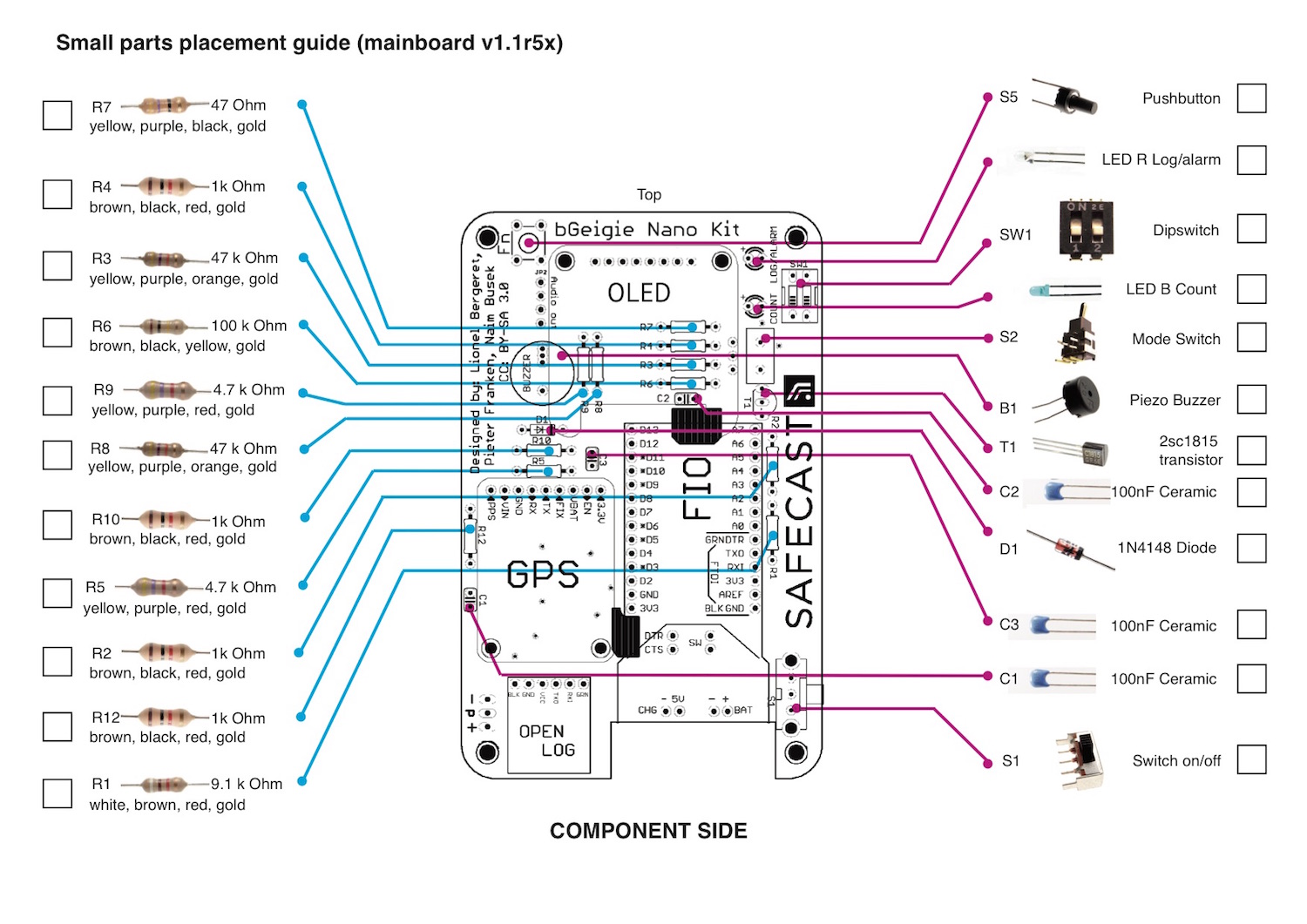
All of the small components go on the main board. Place and solder them, nipping off the leads. Refer to the Small Parts Placement Guide for help with placing these components. You can secure most components in place before soldering them by bending the leads slightly outward; this will allow you to turn the PCB over to solder without the parts falling out. All leads must be closely trimmed so that they project less than 1mm from the surface of the main board.


Top: Component leads bent for ease of soldering; Bottom: Component leads properly nipped to less than 1mm height.
####POLARITY NOTE: What is polarity and why should you care? Several types of electronic components are designed to work with the current flowing in one direction only, while others can work either way. Putting a component that has polarity in the wrong way will usually just prevent the device from working properly, but in some circumstances it could fry a few things as well. So make sure your components are oriented correctly!
The kit contains 11 resistors (of six values, numbered R1-R10, R12), as listed in the Small Parts Placement Guide. Resistors have no polarity so either side can go in either orientation.
Pay close attention to the color ID stripes as listed on the placement guide. (Be especially careful not to confuse the 4.7k resistor, which has a red stripe, with the 47k one, which has an orange stripe).
Double-check for correct placement against the diagram before you solder. If in doubt, the resistors can be measured with an ohm meter. Ask for help if you need it.

Caption: Main Board (PCB) with all resistors installed

Caption: Small components: diode, capacitors, LEDs, transistor
The diode has polarity, so be careful to orient it correctly. The black stripe on one end of the small orange glass part should align with the small white stripe on the component's outline on the board.
While the capacitors in the photo are blue, the ones in your kit may be another color. They have two leads. These capacitors have no polarity and can be inserted in either orientation. Avoid bending the leads too far outward, which can split the capacitors in two.
There are two LEDs, one blue (for "COUNT") and one red (for "LOG/ALARM"). The "case" or “bulb” of LEDs may be colored or may be clear. As of this writing, most Nano kits are supplied with clear LEDs, with the red one marked in red with a marker pen. You can also try powering the LEDs up with a 3V battery to check.

Caption: The LED on the right is red, the one on the left is blue. The LEDs included in your kit may be slightly different so check them before installing.
LEDs have polarity and must be oriented the proper way. One lead is longer than the other. This longer lead is the positive (+) lead, which goes in the hole marked "+" on the board. The side of the plastic case that's flattened is the negative (-) side. Take care not to overheat the LEDs when soldering. Placing a part that has polarity the wrong way is the most common mistake.
— Place the blue LED in the “COUNT” spot and solder in place.
— Place the red LED in the “LOG/ALARM” spot and solder in place.
Note: The LEDs will be more visible if they are installed so they sit about 5mm higher than the main board surface.

Caption: LEDs properly installed
Place the transistor in the "T1" spot. It has three leads, which may need to be spread slightly in order to fit. Mount the transistor so that its shape matches the corresponding “D” shape on the board, with the flat side of the case aligned with the flat side of the diagram.
![]()
Caption: Proper orientation for the transistor

There are four switches.
The dual DIP switch dims the alarm indicators (i.e., turns the lights and sounds on or off; #1: Speaker "clicks" and small Blue LED “Count” blinks; #2: small Red LED “Log/Alarm”). [edit this?]
— Place the switch in the "SW1" spot. It has four pins. Position the switch with the side labeled "ON" toward the top of the board, aligned under the "SW1" label on the board. The switch must be oriented correctly in order for it to work. — Solder the switch in place.
The toggle switch alternates between bGeigie and xGeigie modes. The mode is indicated on the transparent top plate, with positions for "bq/m^2 uS/h" and "log cpm".
— Place the toggle switch above the rectangular outline between transistor "T1" and the blue "COUNT" LED. It has three leads, and a mounting clip with two pins. — Solder them all in place.
This is the power switch. 0 = "off," and 1 = "on."
— Place the power switch in spot "S1." The three leads go in the three center holes in the board, the thick mounting pins go in the outer holes. — Solder them all in place.
The function of the push button switch is user assignable, optional, and not currently implemented. If you would like, you can write code to give it a custom function.
NOTE: The push button switch provided with your kit may be one of several different types. Some have four leads, others have two. Switches that have four legs can easily fit in a vertical orientation (switch facing up). With switches that have two long leads, it's helpful to bend the switch over for clearance, inserted into the two holes away from the board edge. Those that have two short leads also should be inserted into the two holes away from the board edge.

Caption: Your kit may include one of these three types of push button switches, or another type.

Caption: Proper orientation of a two-pin push button switch
— Place the push button switch in the "Fn" spot and solder in place.
The buzzer goes in the large circular spot in the upper left quadrant of the main board, and has two leads. It can go in any orientation. There are extra holes in the board to accommodate buzzers of different sizes. The buzzer should fit flat.
— Insert the leads of the buzzer in the appropriately sized holes and solder in place.

Caption: Mounting holes for piezo buzzer.

Caption: The piezo buzzer may be attached to a cardboard holder. It’s easiest to just snip it off close to the cardboard.
The iRover connector is installed on the rear side of the main board. It connects a three-wire lead from the iRover (the sensor controller and high voltage supply board) to the main board. The kit comes with a 10-pin length, angled male header; cut a 3-pin length from this to use as the iRover connector (more info about the headers that are provided can be found in section 1.2 Daughter Boards below).
[Editors note: add photo of cutting 3pin length]
Temporarily attach the plug of the three-wire lead to a 3-pin angled header. This will help maintain the proper angle of the header and make it easier to handle. The three-pin angled header must be inserted from the rear side of the main board in the position labeled with a diagram and “+p-” and can be soldered from either side of the board. It might be easier to solder it in place on the rear side first, before flipping the board over, for ease of handling. Note that the iRover connector must be attached before attaching the OpenLog, which fits near it on the front side of the main board.

Caption: The iRover Connector is installed on the back of the board in the position indicated by this diagram.

Caption: The three-wire lead temporarily attached to a 3-pin angled header for ease of positioning.

Caption: The iRover Connector in place.

Caption: Solder joints for the iRover Connector for ease of handling

Caption: Proper solder joints for the iRover Connector.
After you've installed all of the small components, the top of the main board should look like this:

Caption: Front side view of Main Board (PCB) with all small components installed.
<a

Caption: Placement guide for daughter boards and headers (Board pictured may be an earlier version but the component placement remains the same).
The bGeigie Nano uses several daughter boards (sometimes called “breakouts” or “shields”), including the OpenLog memory unit, the Arduino FIO processor, the GPS module, and the OLED display. These are attached to the main board with headers, which are long black plastic components with metal pins or legs. Headers are provided in three types (male straight, male angled, and female straight) and several lengths. Most of them need to be cut to the needed length. In many cases they can be easily snapped to the right length, but in some cases a cutting tool such as a knife or nippers may be needed.
Although it is not crucial that the daughter boards be installed in the sequence we describe here, we have found that our method, which begins with those which stand closest to the main board and ends with those highest from it, makes it a bit easier to handle at each stage. The headers for the daughter boards are all mounted from the front side of the main board. They have a “long pin” side and a “short pin” side, and in most cases this orientation is very important. In our method, the long pins of the headers always go into the holes in the board and the short ones project above and are soldered to the breakouts. Please pay close attention to the instructions for each component. To visualize the fit of the parts, study the relevant photos and diagrams and the parts. We have designed the bGeigie Nano and its assembly method so that in most cases the daughter board itself acts as a placement aid. We've found it easier to assemble each daughter board and its headers to the main board first and then solder them.
It’s easy to mistakenly cut headers to the wrong length, so be careful when cutting them. While it’s possible to cut them all beforehand, we’ve found that it’s less confusing if they’re cut as needed.
The following headers should be found in the kit: [CHECK!!]
-
One 40-pin (or “leg”) length, straight, male header.
-
One 10-pin length, angled, male header.
-
One 8-pin length, female header: Used uncut for mounting the OLED display.
(This writes the data to a micro-SD card)
-
Foam tape is used between the OpenLog and the main board to help secure it and to prevent the microSD card from accidentally being inserted into the space between the logger and the main board. Cut a 5mm x 8mm piece of foam tape and attach it to the metal housing on the underside of the OpenLog.
-
Insert a 6-pin length of male header into the 6 holes at the top of the "OPEN LOG" spot on the main board, long pins facing down. Do not solder it yet.
-
Peel the backing from the foam tape, align the OpenLog carefully with the header pins, and press it into position.
-
Solder the 6 pins of the header to the OpenLog from above and to the main board from the rear.

Caption: OpenLog location

Caption: OpenLog component

Caption: Underside of open log with foam tape attached to metal housing.

Caption: 6-pin header inserted long-pins down into main board.

Caption: Header soldered to OpenLog.
The Arduino Fio is a microcontroller board based on the Atmel AVR ATmega328P microcontroller. This is the programmable brain of the Nano. (Fio is the name of this version of Arduino board. FIO also stands for Funnel Input/Output. For background, see the Fio home page on the arduino.cc website; also see the Sparkfun page and wikipedia table of Arduinos.)

Caption: The Arduino FIO module showing the 6-pin angled header.
NOTE: The FIO has a small switch on the underside which should be turned OFF before installing it!
- A 6-pin length of angled male header goes on the Fio itself, in the row of holes beginning with GNDBLK and ending with DTR GRN. It is inserted from the top in the orientation shown (short pins go into the FIO board) and soldered on the bottom (see photo). This is used to connect the Fio to a computer for programming, such as firmware updates, when necessary.

Caption: The Arduino FIO module with the 6-pin angled header in place.
NOTE: For the straight headers, it is easiest to place them all without soldering, and then use the FIO itself as an alignment guide to ensure proper positioning.
-
A 14-pin length of male header goes on the left side of the Fio outline on the main board, holes D13 to 3V3, long pins down.
-
An 8-pin length of male header goes on the upper right side of the Fio outline, in holes A0 through A7, long pins down.
-
There are four pairs of holes in the main board labeled CHG, BATT, SW, and DTR-CTS. Each gets a 2pin male header, long pins down. It’s easy to forget these, so make sure you install them before you solder the Fio to the board.

Caption: 14-pin, 8-pin, and 2-pin headers in place
- Carefully place the FIO onto the headers, aligning the pins into the holes as you go. All of the pins need to be soldered on both the bottom of the main board and to the FIO. It’s a bit tricky to turn the assembly over before both sides are soldered and the FIO firmly held in place. We recommend soldering a pair of pins on the FIO side first — the BAT+ and D13 pins — then carefully turning it over and soldering the corresponding pins on the rear side of the main board. A tool handle or other small object can be used to prop the FIO in place while a pair of pins are soldered on the underside of the main board. Once a pair of pins have been soldered on each side, the alignment can be checked and adjusted as necessary.

Caption: Fio in place, showing location of BAT+ and D13 pins to be soldered first
- Solder the remaining header pins on both sides.

Caption: FIO soldered to the header pins.
- IMPORTANT: Carefully trim all of the header pins on the underside of the main board to avoid puncturing the battery later!
(Global Positioning System receiver, which makes it possible to precisely locate where a reading was taken)
The GPS module is also mounted mechanically using hardware before soldering it in place, to ensure proper positioning.

Caption: GPS module location. Note the two large holes for the mounting hardware.
- The GPS unit comes with a metal battery clip. It's not needed, and in fact, can cause problems if it's installed, so it should be discarded.

Caption: GPS module showing the unused battery clip which may be discarded.
-
Two 5mm-long metal standoffs (like long hex nuts) are mounted to the front face of the main board using stainless steel screws inserted from the opposite side. These will help keep the module and the header properly positioned while soldering them.
-
A 9-pin length of male header goes into the holes at the top of the "GPS" spot on the main board. In this case the long pins should face upward.

Caption: 5mm metal standoffs for mounting the GPS module and 9-pin header in place (note long pins facing upward).
- Align the GPS module to the header pins and attach it to the standoffs using two stainless steel screws inserted from the top. It should be held firmly in a horizontal position, parallel to the main board.

Caption: The GPS module screwed in place.

Caption: The GPS module should be parallel to the main board as shown here.
- Solder the 9 header pins to both the top of the GPS module and to the rear side of the main board.
(Organic Light-Emitting Diode display) There's more than one way to do this, and some variation in hardware provided. This is our currently preferred method for the older board shown on the left.
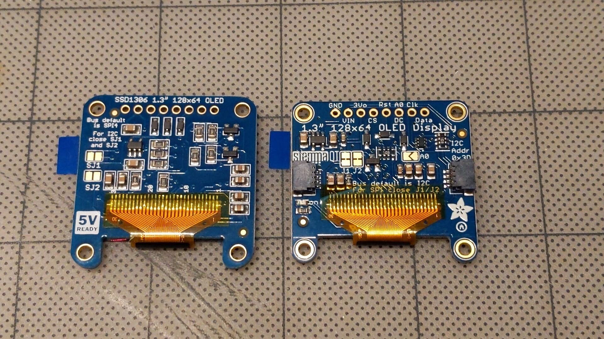
If you received the newer board (on the right, with the Ada Fruit logo), see the new display modification guide.
The module is mechanically attached to the main board in the correct position using hardware before any soldering is done:

Caption: The OLED display module location. Note the two large oval holes for the mounting hardware.
- Attach two 10mm-long metal standoffs at the OLED mounting locations on the main board, using stainless steel screws inserted from the opposite side. The standoffs in your kit may be slightly different from those pictured.

Caption: 10mm metal standoffs in place.
- Insert the long pins of an 8-pin male header into the 8-pin female header. Then insert the female header pins into the main board. Do not solder yet.
Caption: 8-pin male header and 8-pin female header assembled and in place.
-
Align the display module with the protruding header pins and the standoffs, and screw in place using two stainless steel screws. Do not tighten the screws yet.
-
Solder the female header pins to the main board from the rear side, and the male header pins to the display module from the top. The display will be easily removable.


Caption: OLED display module installed, with black plastic portion of the male header in place
The display should be functional at this point, but because there are slight high differences between the headers and the standoffs we prefer to improve the fit as follows. This is optional.
OPTIONAL STEP!
IT MUST BE DONE CAREFULLY TO AVOID BENDING THE HEADER PINS. IF YOU ARE NOT FULLY CONFIDENT OF YOUR SKILLS DO NOT ATTEMPT IT.
This optional step involves removing the black plastic portion of the 8-pin male header attached to the OLED display module. This will allow the OLED display module to seat properly.
- Remove the display and turn it over. The 8-pin male header should have been soldered to the display at this point and remain attached. Using needle-nosed pliers, nippers, or a similar tool carefully pry the black plastic piece away from the display until it is free.

Caption: Removing the black plastic portion of the 8-pin male header attached to the OLED display module.
- Reattach the display module using screws as before.

Caption: When the black plastic portion of the male header is removed, the assembly will look like this. Note: In this photo the mounting screws have not yet been replaced.
END OF OPTIONAL STEP
!! IMPORTANT: Make sure you're running the most recent firmware. You can download it at: https://github.com/Safecast/bGeigieNanoKit
Once you've finished assembling the main board, including the daughter boards, it's a good idea to do a power on test. This involves temporarily connecting the battery and turning the unit on. We recommend doing this because it's much easier to fix problems that might be due to misplaced or poorly connected components before the unit is fully assembled. The same test sequence can be used for diagnostics after the entire nano is assembled.
A. Before connecting the battery:
-
There is a small ON/OFF switch on the underside of the FIO. Make sure that it is in the OFF position, i.e. towards the 6-pin angled header. If you didn't remember to do this before attaching the FIO, it's accessible (barely!) on the assembled unit. If this switch is in the ON position, the unit will power up as soon as the battery is connected, and power switch attached to the main board will not function.
-
Remove the micro-SD card if it has been inserted into the open lock
-
Set the switches on the main board:
- DIP switch: both in ON position
- Toggle switch: Can be in either position, but we suggest moving it to the down position (log/cpm)
- Power switch: in OFF position
B. Plug the battery connector to the FIO.
C. Turn the power switch to ON
What appears on the display may change with upgrades to the firmware. With firmware version 1.4.1, in a moment, the display should show:
-
The splash screen, with the word SAFECAST.
-
The welcome screen:
- Unit version number
- Unit ID number
- Battery charge level
- Mode indicator
- Alarm setting
- Customizable text string (useful for putting a name)
- The main screen
D. With the toggle switch in the down position (logging mode/CPM), (during a mid-assembly test, with the sensor not connected)
Left column:
- 0 CPM
- 0 uSv/hr
- NO SD CARD (when the SD card is installed, this should display Date/time).
Right column:
- battery charge indicator
- No GPS (probably, though in certain conditions it may lock quickly and show the number of GPS satellites it's receiving signals from)
- XXm (height)
- XXhXXm (elapsed time)
E. With the toggle switch in the up position (Bqm2/uSv/h), the display should show (see photo below):
In a single column:
- 0uSv/hr
- 0CPM 0Bq/m2, alternating with Mx=0 (max reading since reset)
- Ds=0 (cumulative dose since reset)
- NO SD CARD, etc, as above
F. Several LEDs should illuminate.
-
The red power light should be glowing visibly glow beneath the upper end of the Fio.
-
A small red LED on the GPS breakout should blink.
-
A small blue LED on the OpenLog light should blink.
This completes the basic test (additional tests can be performed after completion (see section 4 below):

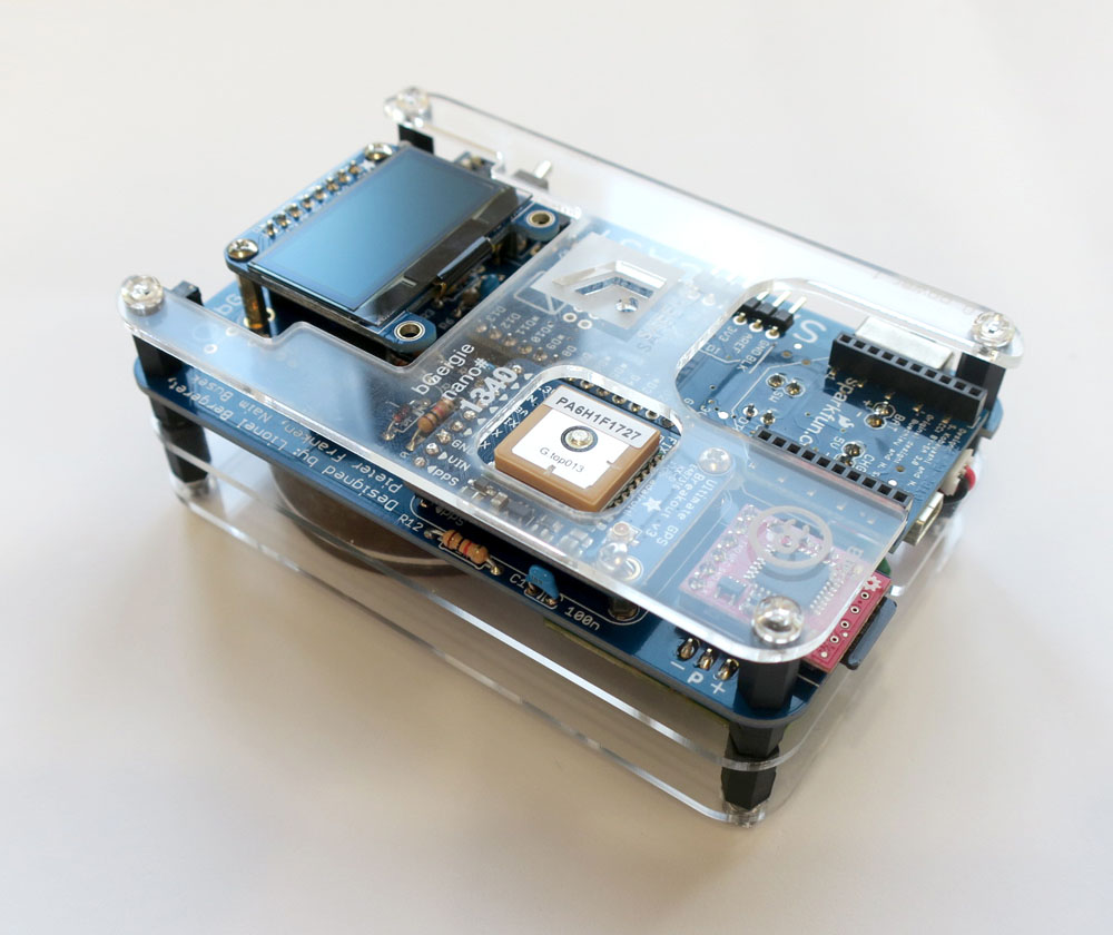
Caption: Successful power-on test. The battery is attached and the main screen is being displayed.

Caption: Front, back, and middle plates. Remove paper backing before installing.
There are three laser-cut acrylic plates: front, middle, and back. Now is a good time to attach the front plate, to make it easier to handle the unit during the remaining steps. The front plate has the Safecast logo, the unit serial number, and cutouts for the display, GPS, and FIO. Remove the brown paper backing from the plate and attach it to the black plastic standoffs using four clear acrylic screws.

Caption: Front plate attached using four clear acrylic screws

Caption: Size comparison of 1200mAh (A, top) and 2000mAh (B, bottom) batteries.
The bGeigie Nano uses a 3.7V Lithium Polymer (Li-Po, Li-Poly) battery. The one included with your kit will probably have either a 1200 or 2000mAh rating. Attention: The battery is encased in a thin mylar membrane. If this is punctured, the battery can be hazardous, and fire can possibly result. Handle it carefully! To guard against this hazard a plastic protective sheet is provided, and foam tape is used to provide a protective buffer space between the battery and the other components.
Charging the new battery full with the first use is recommended. The percentage of battery charge appears in the startup screen and a graphic indicator is displayed in the bottom right during use. The 1200mAh battery will give 24-30 hours of use on a full charge, while the 2000mAh type will give over 40 hours. Recharging is via a cable between the miniUSB port on the bottom of the Fio to a USB on a computer or a correctly rated miniUSB recharger (such as https://www.sparkfun.com/products/10401). (Do not connect a miniUSB cable from a power-ON USB source without first turning Power OFF on the Nano.) Replace a broken or worn-out battery with one with the same voltage rating. If higher-voltage batteries are used the Nano charge circuit may overheat.

Caption: Battery. This one is 1200mAh, Your kit may contain a slightly different type.
This step uses double-sided foam tape which is a bit hard to remove if something goes wrong. It’s best to do a dry run before actually attaching the battery with the foam tape! There is more than one way to attach the battery, but this is our currently preferred method. There is no soldering in this step.
-
First tape layer: Cut four pieces of foam tape about 2cm in length, and attach them to the corners of the battery.
-
Protective plastic sheet: In the photo, the protective sheet is pink, but the one in your kit may be clear or another color. Cut it so that it extends about 5mm beyond the battery on all sides. Peel the paper backing from the tape and carefully attach the plastic sheet to the battery.
-
Second tape layer: Attach four more pieces of foam tape, about 2cm long, at the corners like before.

Caption: Steps for attaching foam tape and the plastic battery protector. Left: First layer of tape. Four pieces attached at the corners of the battery. Center: The plastic battery protector sheet trimmed so it’s larger than the battery by about 5mm on all sides, then attached to the first layer of tape. Right: Second layer of tape, again four pieces attached at the corners.
- Attaching the battery to the main board: The battery will align with the large white Safecast logo on the rear side of the main board. The battery lead should extend from the bottom, towards the side with the connectors. Peel the paper backing from the tape, carefully position the batter and press it into place.

Caption: Left: The battery should be positioned above the Large white Safecast logo on the rear of the main board. The battery lead should extend from the bottom. Right: Battery in correct position
- When properly installed, there should be about 3mm of space between the battery and the main board, wit the plastic sandwiched in-between.

Caption: Side view showing the proper space between the main board and the battery, with the plastic protector in-between. This will help ensure that the battery will not be punctured by any remaining sharp leads etc protruding from the rear of the main board.
- The battery lead will be more easily routed to its connector if it is carefully bent in a u-turn fashion.

Caption: The battery lead bend.
- It will be easier to route the battery lead to the connector and avoid it sticking out if it’s given a single-loop twist. Leave the battery disconnected for now, however, to avoid problems during the next assembly steps.

Caption: The battery lead with fit more easily if the lead is given a single-loop twist like this.
Overview: Two important components, the iRover power supply and the sensor, are mounted to the middle acrylic plate. As with the other steps, orientation and alignment are crucial. There are only four solder joints to be made, however.
(The iRover is the controller board and HV (high voltage) supply for the pancake sensor) The iRover is attached to the middle plate using 5mm-long metal standoffs and screws. Before this can be done, however, the three-wire lead (used as a placement guide for the iRover connector in step 1.1.5 iRover Connector) must be soldered to the iRover. Most iRovers currently supplied have three small holes for this connection. Others, however, may have three small pins or metal bumps. We will show the procedure for iRovers with three holes. If the type included in your kit is different, everything other than the solder connections themselves will be the same.
- The “front” of the iRover has a thick red wire sticking out of it. The 3-wire lead will be attached from the opposite (rear) side. Locate the three holes on the rear side.

Caption: Rear view of iRover, showing three holes for connecting the three-wire lead. The iRover in your kit may be slightly different
- Split the ends of the three wires slightly and strip them to leave about 5mm of wire exposed. (The colors of the 3-wire connector included in your kit may be different, but red wire will always be positive). Tin the ends of the wires to make inserting them easier. Insert the stripped ends of the three-wire lead into the holes in the iRover, paying careful attention to the orientation shown in the photo. The red wire should go nearest the closest edge as shown. Solder the wires in place from the opposite side.

Caption: Placement of the stripped ends of the three-wire lead into the holes in the iRover. The red wire should go nearest the closest edge.

Caption: The iRover with the 3-wire lead attached.
- Remove the paper backing from the middle plate and orient it as shown in the photo, paying attention to the sensor placement outline. Attach two 5mm stainless steel standoffs to the two small holes near the bottom of the plate (not the corner holes!). Attach them with stainless steel screws inserted from the back of the plate.

Caption: The middle plate with two 5mm-long metal standoffs attached using screws from the bottom side. Pay careful attention to the orientation relative to the sensor placement outline.
- Position the iRover board on the standoffs, and attach it with two stainless steel screws inserted from the top. Make sure the side of the iRover with the 3-wire lead is on the bottom, and the thick red wire with the black connector on the top face is roughly centerline with the plate.

Caption: When attaching the iRover to the middle plate, the 3-wire lead must be routed through the notch as shown.
- Place the middle plate over the black plastic corner standoffs, and slide the 3-wire lead onto the iRover connector on the main board. The red wire must be closest to the edge of the main board as shown in the photo. The clearance is a little tight so you may need to use needle-nose pliers or a similar tool.

Caption: The 3-wire lead must be connected with the red wire closest to the edge as shown
- Push the middle plate onto the black plastic corner standoffs, and attach the four remaining ones. They should be finger-tight.

Caption: The middle plate with the iRover correctly mounted, and the plate attached to the black plastic standoffs.
The pancake GM (Geiger-Müller) sensor is very delicate. Take care to protect the sensor membrane during the assembly process! Most bGeigie Nano kits are provided with a protective mesh screen already attached. If the one in your kit has not yet been attached, please complete section 2.2.1 Sensor Screen Attachment below before continuing.

Caption: GM pancake sensor with a protective mesh screen attached.
Once the sensor has been connected to the battery it also presents an electric shock risk (about 500 volts! Yow!), so be very careful about touching it. Especially the iRover connection where the bare wire is soldered. Also take care not to let the bare wire touch the silver metal connector. The included shrink tubing is to help prevent that.*A thin uninsulated silver cathode wire is initially coiled against the sensor case. Gently uncoil this and wrap it under the anode post and up out of the way. Making sure it doesnʼt touch the bare metal surface. See photo below.
- The sensor is attached to the middle place with double-sided foam tape. The etched outline on the plate may be enough to help you position it accurately, but we recommend you do a test fit using the opening in the rear plate as a guide, as once attached it’s very difficult to re-do. Attach a couple of pieces of foam tape to the bottom of the sensor as shown in the photo, and before peeling the backing tape off, practice dropping the sensor into place. When youʼre sure you can do it accurately, peel the tape, drop it in place, and carefully push it down to ensure a secure bond. Then remove the rear plate for the following steps.

Caption: Foam tape attached to rear of sensor for mounting.

Caption: Sensor installation. Note the rear plate temporarily installed to use as a placement guide. The silver cathode wire is carefully wrapped out of the way. It’s best to perform a few dry runs before peeling the backing from the foam tape.
-
The sensor gets two connections to the iRover: the anode connection, which is the thick red wire with black connector, and the cathode connection, which is the thin, uninsulated silver wire.
-
Most iRovers have a small hole for connecting the cathode wire, but infrequently some will have a small wire loop or a metal bump. The photo shows the cathode wire placed into a hole-type connector. It will need to be trimmed to length (but not too short) and soldered into place. Needle-nose pliers may be helpful for threading the wire into the hole.

Caption: Placement of the cathode wire into the small hole in the iRover
- Slip the short length of shrink tubing onto the thick anode wire. The black anode connector is simply pushed onto the metal post, and should have a tight friction fit. Slide the shrink tubing towards the sensor so that it covers the exposed metal on the anode post.

Caption: Cathode wire soldered in place, and anode wire connected with shrink tubing slid into place.

Caption: Sensor installed.

Caption: The tubing can be shrunk using a heat gun or a lighter. Either way care is necessary not to damage the components and to prevent burns.

NOTE: This step is only necessary in cases where the sensor provided in the kit does not alreayd have the screen mesh attached.
The copper mesh cover should be attached to the pancake sensor so that it protects the membrane. We've found that a thin coat of clear acrylic nail polish carefully applied to the edge of the mesh works well as an adhesive. It can also easily be removed later if needed by using nail polish remover.
Use clear nail polish or "nail top coat," without glitter or other anything like that in it. Only a thin coat is needed. You should apply it to the edge of the mesh because it's easier to handle than the sensor. Carefully position it on the sensor as shown in the photo, and press down on it lightly with your finger for a minute or so until the polish starts to set. Let it dry for about 5 minutes.
- Now is a good time to attach the rear plate, using 4 black plastic standoffs and nuts.

Caption: The bottom acrylic plate in place. It is fastened using four acrylic nuts.
*Check all the plates, standoffs, screws, and nuts now to make sure everything is where it should be. It all disassembles fairly easily if you need to change something.

Caption: Side view showing the proper stacking of plates and standoffs.

Caption: Completed Nano, right-side up

Caption: Completed Nano, upside down

Caption: Completed Nano, front view

Caption: Completed Nano, back view

Caption: Completed Nano, right side

Caption: Completed Nano, top end

Caption: Completed Nano, back end

Caption: Completed Nano, left side
The Pelican case is a standard Pelican Micro Case 1010 model. (The sticker with the manufacturer's logo can be peeled- and cleaned-off.)

Caption: Using tape to remove label adhesive
The case has a removable rubber liner (black, yellow, blue or red). A hole must be cut in this removable rubber liner to fit the pancake sensor. There is more than one way to do this:
-
Itʼs easiest to use the opening in the rear plate as a hole-cutting template. Push it snugly into the rubber liner, and trace the circular opening with a pen, pencil, or thin marker. Remove the liner from the case before cutting the hole in the rubber liner.
-
Use an X-acto, Olfa, or similar knife to cut the liner hole.

Caption: Cutting a hole in the Pelican case liner with a knife

Caption: Joe's method of cutting a hole in the liner using a sharpened can
Safecast community member Joe devised this hack to simplify cutting neat holes for the sensor in the rubber lining of the Pelican case. This method takes advantage of the fact that the sensor is almost exactly the same diameter as a standard aluminum drink can. To use this approach:
- Remove the top face of the can, using a sturdy knife or another method (Joe uses a razor saw).
- Sharpen the thick aluminum edge slightly, as shown in the photo. It doesn't have to be extremely sharp to work.
- Place the rubber liner on a block of wood or similar surface, and use the rear acrylic plate (the one with the hole for the sensor) to gauge or mark the position of the hole.
- Align the can carefully, push down hard with your palm, and rotate it slowly a couple of times.
This method requires a bit of a knack, but it makes the best holes!

-
Put the liner back into the plastic case, and gently but firmly insert the assembled bGeigie Nano into the liner. Check that the sensor is properly aligned with the opening in the liner (alternatively, place the Nano into the liner and insert them together into the case). It should be a very snug fit. Close the case. The clasp shuts tightly with a click.
-
Eight clear, neoprene feet are provided in the kit. Place them on the four corners of the top and bottom sides of the case. While the feet are optional, they often make it easier to mount the device.
- Strap(s) are also provided to make it easier to mount the Nano on a car or other vehicle. (See #10 “Mounting tips” in Operation Manual.)
In this configuration, the bGeigie Nano is fully operational for most types of data gathering.

To test the counter function with the sensor disconnected, use a knife blade or other small piece of metal to make a brief connection between the plus and middle pins on the triple-connector. The blue COUNT LED should light up, the speaker should click softly, and the display should show counts each time the pins are touched.
If the blue LED doesn't blink, it was probably installed with the polarity reversed. Another possibility is that the polarity of the diode (D1) is wrong. Remove and solder those components again if necessary.
- Because the SD card is only detected at startup, switch the power off first.
- Insert the SD card.
- When the unit powers up, a date/time reading should appear at the bottom of the left column (replacing NO SD CAD), but it will not be correct until the GPS has locked.
Test the GPS lock by putting the unit near a window while it's powered on. After a few minutes, the "No GPS" indicator will change to indicate the number of satellites it has locked to (e.g., "4 [upcaret]"). A height reading should also appear (e.g., "3m"). Since firmware version 1.3.0, Nano initiates a GPS reset procedure when there's no SD card inserted at boot time. To test the GPS lock, make sure you've inserted the SD card first. See the bGeigie Nano Operational Manual for more information.
To test charging the battery, attach a mini-USB cable to the Fio, then to a computer or USB charger. A yellow charge light should glow visibly underneath the Fio. The light will go out when the battery is fully charged.
As described above, the bGeigie Nano can be used in LOG mode (toggle switch down) for mobile mapping of radiation, or in SURVEY mode (toggle switch up) for measuring surface radiation etc. It must be in LOG mode with a GPS signal lock in order to generate radiation map data that can be uploaded to the Safecast database (api.safecast.org). By far the most common use is to log data with the Nano attach to a vehicle. The short video linked below explains how to use the two modes, attach the nano to a car, etc..
Schematics are available in Eagle format in the Safecast GitHub repository.