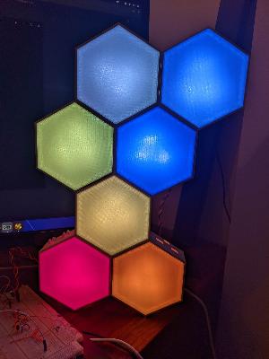
Hexagon wall v2
To properly build the hexagon2 project, you'll need the following:
# Install build tools
sudo apt-get install gcc-arm-none-eabi jq

# Configure rust
rustup default nightly
rustup target add thumbv7em-none-eabiIn order for your project to build correctly, you'll need to run the following command:
./build.sh
The build script will generate a .hex file and place it in a folder called out. This hex file is compatible with the teensy 4.0 and can be flashed with the teensy-loader utility.
CAUTION: Do not build this in release mode. It optimizes a lot of stuff away, and can cause problems.
- 1x DC Barrel Jack
- 1x DS18B20
- 1x 4.5k Resistor
- 1x 100uf Capacitor
- 1x ESP8266
- 1x Teensy4.0
- 3x WS2812b SMD
- 3x WS2812b SMD
- 2x Right-Angle Headers
- 1x M4x12 Bolt
- 1x M4 Nut
- 2x M4 Washers
There are two circuit boards which need to be fabricated. The gerber files are located in the gerber/ folder. You will need:
- 1x brain_v1.x.zip
- nx unit_v1.x.zip
You need 1 brain per project and as many units as you like. Each hexagon will require 1 unit.
NOTE There is SMD soldering required for this project. If you don't want to solder yourself, a BOM and Pick and Place file are included inside the unit.1.x.zip file. This only applies to the individual hexagon units. Brain still has to be manually assembled.
Each WS2812B takes 50mA and one hexagon unit has 3 of those. So that means you're looking at 150mA draw per hexagon unit. The trace in all the circuits (as of the August 6th upload) is pretty thick (1mm) which can support 2.3A with 10 degrees (C) of thermal dissipation. That is about 15 hexagon units that you can string together before you'll reach capacity. You can go more, but things will start getting toasty.
To mitigate this problem, all boards have a "POWER JUMPER" section. You can connect wire to the POWER JUMP (like, say, 18 guage wire) and splice it in throughout the final assembly. in this way, you can route the power in a much more controlled fashion.
There are a few parts which need to be 3D printed. You can find everything in the 3d/ folder. The important things are pre-generated in .STL format. You can also find all the openscad source code for each object.
- hexcore.stl
- hexshield.stl
- snapfit.stl
This is the actual hexagon which you will mount the circuitry to.
Infill 15 or 20%
Pattern Rectilinear is fine
Material PLA Recommended
Color White
This is the faceplate which attaches to each hexagon node using a friction-fit mechanism.
Infill 100%
Pattern Rectilinear Required
Material PETG Recommended
Color Transparent
This is the little snapfit connector that you can use to attach hexagons together.
Infill 15 or 20%
Pattern Rectilinear is fine
Material PLA recommended
Color Any