Due to bandwidth limitations I was forced to remove some files. If you can't download some of the larger files, go to Printables. You should find the most important files there. Printables: https://www.printables.com/model/606030-3d-printed-hexapod
Seems like you want to build a Hexapod. Don't know why but since you're here, might as well tell you about the most important features about my design:
- Cheap: 120 € (see Parts (toBuy) file)
- RGB: 271 individual RGB LEDs
- Cable management: Cables are routed inside the leg. no cable loop that tangle
- ORP compatible: compatible with the Open Robotic Platform modules
- Bluetooth control: Remote control via phone app
If this hasn't convinced you might I suggest watching my videos on the design and build.
Leg: https://youtu.be/Ta3ILBvA57U
Body & first Steps: https://youtu.be/FBk1Pa01zQ4
Since you are reading this I assume you are at least considering my design. I have some instructions on Instucatbles and Hackster.io if you want to take a look at that. Instructables: https://www.instructables.com/3D-Printed-Hexapod/ Hackster.io: https://www.hackster.io/sir-kuhnhero/3d-printed-hexapod-05a60c
You can also find all the most important files on Printables: https://www.printables.com/model/606030-3d-printed-hexapod
All the 3mf files are oriented correctly with the needed support material. My parts are design in a way that uses minimal support material. See “Parts (toPrint)” Excel sheet.
If you don't know what and where to buy take a look at the "Parts (toBuy)" Excel sheet. Those are the parts I bought and where. You can also update the prices and it will automatically calculate the final price. Everything I listed is without shipping since that varies drastically.
If I didn't buy it or the link doesn't work anymore I linked to where I would buy.
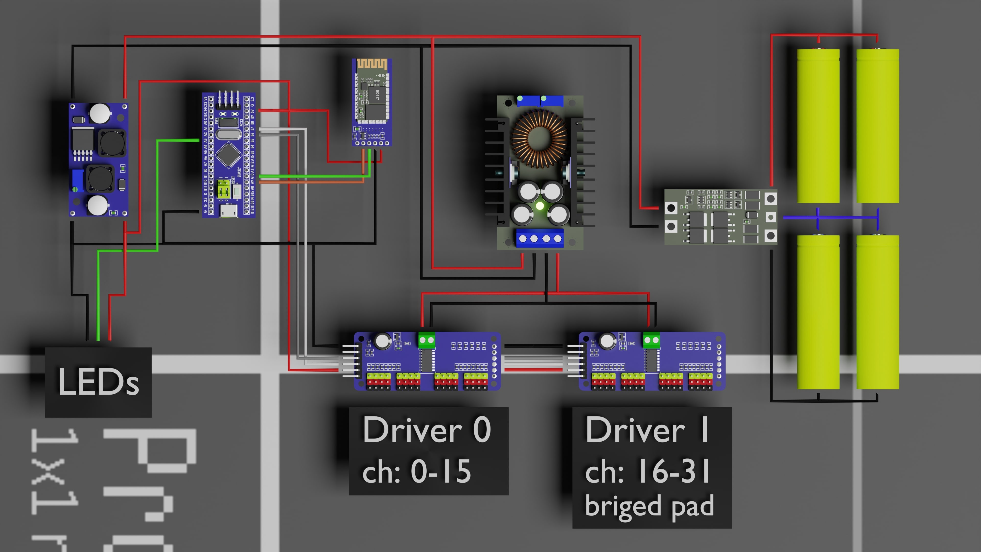
Connect everything like in the wiring diagram above. You will see where to place te servo drivers in an image bellow. Be sure to use shielded wire for the connection between the STM32 and the servo drivers. I had some problems with interference without it.
One thing missing here is the XT60 connection between the battery and the rest of the circuit. You need a way to shut the hexapod down and recharge the battery.
The LEDs are all connected in series in this order: Eye Centre, Eye middle ring, Eye outer ring, bottom ring, leg[ (front right) root -> tip (proceeding clockwise)
For the servos you can connect them to wherever is easiest. However you will need to set the channel for each servo in the "output.cpp" file correctly.
Leg[0].Servo[0].ch = 2;
Leg[0].Servo[1].ch = 1;
Leg[0].Servo[2].ch = 0;

Leg[1].Servo[0].ch = 6;
Leg[1].Servo[1].ch = 5;
Leg[1].Servo[2].ch = 4;

Leg[2].Servo[0].ch = 13;
Leg[2].Servo[1].ch = 14;
Leg[2].Servo[2].ch = 15;

Leg[3].Servo[0].ch = 18;
Leg[3].Servo[1].ch = 17;
Leg[3].Servo[2].ch = 16;

Leg[4].Servo[0].ch = 25;
Leg[4].Servo[1].ch = 26;
Leg[4].Servo[2].ch = 27;

Leg[5].Servo[0].ch = 29;
Leg[5].Servo[1].ch = 30;
Leg[5].Servo[2].ch = 31;
The Leg naming is as followes:


On that node ensure that you bridge the first solder pad on one of the servo drivers. This will ensure that it uses a different I2C address. This second driver will continue the channel numbering of the first (16-31).
The code has been written in Visual Studio Code with the platform IO extension.
To Upload it make sure you have both installed and add the folder bellow as a project.
From here upload the code. Be sure to use an ST-Link for this. You can use a simple FTDI Programmer or something similar but you will have to unplug the Bluetooth module to connect it and change the "upload_protocol" in the platformio.ini file from "stlink" to what your programmer requires. Check here for more info.
[env:genericSTM32F103C8]
platform = ststm32
board = genericSTM32F103C8
framework = arduino
debug_tool = stlink
upload_protocol = stlink
lib_deps =
  adafruit/Adafruit PWM Servo Driver Library@^2.4.1
  fastled/FastLED@^3.6.0
I had some issues with my ST-Link a while ago and had to switch to an FTDI programmer. This ended up looking like this:
[env:genericSTM32F103C8]
platform = ststm32
board = genericSTM32F103C8
framework = arduino
upload_protocol = serial
lib_deps =
  adafruit/Adafruit PWM Servo Driver Library@^2.4.1
  fastled/FastLED@^3.6.0
If you want to deactivate some functions, for example the LEDs, for some reason you can do that in the "header.h" file by commenting out what you don’t want. This can be great for testing new features.
#define WS2812B_LED

#define SERVO
//#define SERVO_CALIBRATION

#define DEBUG
// #define DEBUG_SERIAL
// #define DEBUG_LED

#define BLUETOOTH
You will also need to fine tune the servo angles by setting the angleOffset for each servo in the output.cpp file. If you set your values correctly it should look something like this. To make this easier you can uncomment "#define SERVO_CALIBRATION" in the "header.h" file. This will move every leg to it's origin.

If you install the application you will get a message saying this might be dangerous to install. This is normal so don't worry. If you don't trust me take a look at the MIT App Inventor project files and compile it yourself.
Once installed make sure to allow "Nearby Devices". This is required for the app to find available Bluetooth devices.
Note that there are slider for controlling the Hexapods LEDs but that is currently disabled to reduce latency.
Turn your Hexapod on and pair to the Bluetooth module in you phones Bluetooth settings (only do this once). The default password is 1234 or 0000.
Now open the Hexapod Remote app and connect to the Bluetooth module. Once connected the Hexapod will have a simple startup animation and now you can control the hexapod using the two sticks.
Note that if you have changed something with #define at the beginning of header.h this behaviour might be different.
To be clear, my design is NOT perfect. Here are all the problems I have:
- highly integrated leg design: routing the cables inside the leg looks awesome but makes assembly more difficult. If you were to not use LEDs this problem would largely be negated.
- Current spikes: the hexapod is able to handle some load but especially at times of a power spike the Buck converter powering the servos can be insufficient. So you might want to use two or buy a more powerful one.
- I2C buss instability: I had problems with the I2C buss between the STM32 and servo drivers breaking down causing the Hexapod to freeze. I was able to fix that by using shielded cables, but it required some trial and error.
- incomplete Code: Not all features have been added in code. For example no LED animations beside the startup animation.
If you have any questions or suggestions consider writing me a comment.
Happy Making :)