this
With the advancement in internet technology in the last 30 years , a new market of devices has emerged that combine the use of the internet and sensors to exchange information between them in a meaningful way. These devices are called Internet of Things or in short IoT . The mass marketing and adoption of these devices has made easily available to many people which implement them in their home without proper infustractior with many of them being vulnerable to low level attacks. There have been studies and testing done on IoT devices in regards to network penetration testing but there is a lack of research in the field of Radio Frequency. The increase in IoT device attacks has surge drastically in the past few years , specifically in 2019 there was a record of 2.9 Billion attacks collected by honey pots on IoT devices. That was a 300% increase in attacks in comparison to the previous year where there where only 819 Million attacks.
One of the major attacks which have compromised many Zigbee based IoT devices is the Zigbee Worm attack which exploits hard-coded symmetric encryption keys in the Zigbee protocol that allow the worm to take control of the devices . This then allows it to spread to other nearby zigbee devices allowing for full control of the network . This can be done as far as 400 meters away which makes it even more difficult to track and trace.
The worm can then spread from a single smart bulb to those nearby thanks to the use of these skeleton keys. [cite]https://www.theregister.com/2016/11/10/iot_worm_can_hack_philips_hue_lightbulbs_spread_across_cities/
[cite](K. Rawlinson, “HP study reveals 70 percent of internet of
things devices vulnerable to attack”, 2014)
In this section we shall explore related work which have been done in the past on radio frequency vulnerabilities in Iot devices. We shall also critically analyse the results and conclusions of the related works as well as the methodologies and testing environments used.
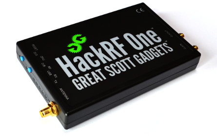
The HackRF is a half-duplex sdr transceiver designed for RF investigation. It has an operating frequency of 1Mhz - 6Ghz with a 8-bit quadrature sample rate. The hackrf has a maximun transmition power of 30mW this makes it suitable for transmittion at close ranges but it prone to emission of sperodic emissions which could compromise nearby equipment if used with amplification equipment. The HackRF is compatable with GNU-Radio allowing it be calibrated to work with multiple other equipment and protocols. One of the main disadvatages of the HackRF is its subpar receive perfomance . In our case we added a Temprature Compensated Crystal Oscillator (TCXO) to the HackRF to increase the receive performance to minimise frequency drift while receiving for long periods from time. We will explore the usefulness of a TCXO in the context of this research in the next section.[REFERENCE] The TCXO chip used in our hackrf is a Si5351 which is a high performance crystal oscilator which can operate at 0.1 PPM accuracy.
The NESDR is a low cost SDR receiver capable of receiving from 25Mhz up to 1.7 Ghz. Its wide popularity has given rise to multiple software packages supporting it with a wide range of decoding protocols such as DMR,APRS,LORA,P25,FSK, etc. The low cost of the NESDR makes it a good choice for testing and development purposes as is it has a much greater sensitivity than the HackRF when paired with a resonant antenna. In contrast to the HackRF the Smart SDR is only capable of receiving but has an overall better software compatibility. RTL-SDR based devices are based on two chips . The RTL2832U demodulator chip and the R820T2 tuner chip. It also features a 0.5 PPM(parts per million) low noise Temprature Compensated Crystal Oscillator (TCXO) chip capable of keeping the tuner in sync with the demodulator as it heats up. Since heat is a major factor in the signal stability of the tuner it is important to keep the device in a stable temperature range.
[cite]( add info from rtlsdr.org)
Temperature Compensate Crystal Oscillators are used to correct the voltage of the tuner chip which results in variations in frequency over temperature differential.The voltage correction is applied to varactor diode located on the crystal circuit which varies the crystal frequency by a miniscual amount. This results in a much more stable frequency. TCXO can reach a stability of 0.1 PPM but there are some issues being introduced. When a TCXO chip resides at a temperature extreme for long periods of time might a exhibit a frequency shift when it returns back to its normal ambient room temprature. This is a major issue for long term operation of the device as it might skew the results of the project. For example, whe monitoring a device for long periods of time so we can sniff packets being transmitted by the device we might experience a shift in frequency causing loss of packets even when we are "monitoring" on the correct frequency of operation. This hysterisis error is temporary but it is imporatant to take into account when monitoring a device for long periods of time.
[cite](Design Technique for Analog Temperature Compensation of Crystal Oscillators)
( @ARTICLE{7065313,
author={Huang, Xianhe and Liu, Dong and Wang, Yan and Chen, Pingping and Fu, Wei},
journal={IEEE Transactions on Circuits and Systems II: Express Briefs},
title={100-MHz Low-Phase-Noise Microprocessor Temperature-Compensated Crystal Oscillator},
year={2015},
volume={62},
number={7},
pages={636-640},
doi={10.1109/TCSII.2015.2415652}}
)
The Zigbee protocol is a IOT specific protocol used for the transmission of data from sensors and automotation control networks using the IEEE 802.15.4 standard. It uses very low data data rates of around 250Kpbs which operated on the microwave frequency allocation of 868 , 902-928 Mhz and 2.4 ghz frequencies. Usually higher frequencies are used to transfer data between devices at higher datarates but closer range. Usually Zigbee devices have a maximum range of 100m (assuming propagation allows)
https://www.sciencedirect.com/topics/engineering/zigbee-protocol
The structure of the Zigbee network is consists of three main devices. The coordinator , Router and End Device . A zigbee network cannot function without a coordinator as is bridges the device with the network . The coordinator is in charge of storing and the information sent by the end device while the router with re transmit the data to the appropriate device .
Bluetooth is a short range low power mode for transferring data between two devices. It is usually used to sync between devices in a mesh network, send files between devices , stream music etc. It operates on the 2.4Ghz portion of the spectrum utilizing 79 channels of 1mhz bandwidth each. Bluetooth network operates using a frequency hopping to minimize interference to other devices and try to mitigate any potential impact it might have to other devices. When two devices connect to each other using Bluetooth they initiate a handshake signal which usually requires authorization of both parties with some sort of pop up notification or by entering a one time password. Bluetooth devices are organized a star topology meaning that there is one master server which sends data to multiple slave nodes. For example a master server could be a phone and the slaves are the wireless earphones or speakers. A Bluetooth packet is made up of three parts :
- Access Code
- Packet Header
- Payload
This allows the protocol to work either Synchronous mode for voice calls or Asynchronous Mode for data transfer.
https://www.scientificamerican.com/article/experts-how-does-bluetooth-work/
https://techspirited.com/how-does-bluetooth-work https://ieeexplore.ieee.org/abstract/document/824570?casa_token=dUcTveas6GkAAAAA:B5RAywdmD74wiBePLyszuzFhUsvzuin--HUvxDcrDBfQY0qjGUhoPZE0zQevAXHAdCjfZtP4
The Bluetooth controller is in charge of implementing the physical layer (Layer 1) of Bluetooth which is made up of the radio , base band and link management layer. It establishes the initial communication with the destination device using the Host Controller Interface . The link management layer is in charge of creating that initial connection between two devices in turn use the base band layer to create an access control system through the radio link layer .
"Multi-level Bluetooth Intrusion Detection System" (cite)
The HCI layer is a mediator between the controller and host. The host uses the host controller interface to establish a link between it and the Bluetooth controller .
"Multi-level Bluetooth Intrusion Detection System" (cite)
The Bluetooth Host houses the Bluetooth protocols logical stack components which allow the Bluetooth protocol to be used with different applications .
"Multi-level Bluetooth Intrusion Detection System" (cite)
Every electronic device which utilizes Radio frequencies for communication and operation such as WiFi , zigbee , lora etc.. are prone to harmonic frequency emission . This is one of the fundamental properties of electromagnetic radiation . Electronic devices are under heavy regulation from bodies like the FCC which are in charge of reducing and controlling the behavior of these emissions .
| Harmonic | No. of waves | No. of Nodes | No. of anti-Nodes | Length vs Wavelength Relationship |
|---|---|---|---|---|
| 1 | 1/2 | 2 | 1 | Wavelength = (2/1) * L |
| 2 | 1 | 3 | 2 | Wavelength = (2/2) * L |
| 3 | 3/2 | 4 | 3 | Wavelength = (2/3) * L |
When a wave oscillates it will produces harmonic waves with a reduction in bandwidth every time which results in an oscillation on a different frequency . In our case this could allow for attacks to be carried out by using even less "sophisticated" equipment by transmitting on lower frequencies.
Harmonics can cause unintended interference to other devices operating on the frequency which the harmonic will oscillate. As we get closer to the third harmonic and the wavelength increases it will increase the noise floor of the electrical signal which in turn can cause "jamming" of legitimate signal reaching their intended receivers . Furthermore , they can cause the capacitance level of power factor capacitors to flactuate and inductance of the power supply to become unstable causing the device or neighbouring devices to behave irregularly.
Harmonic Spurious emission are also a huge issue in electronic devices as they produce unwanted oscillations close to the fundamental frequency as-well as harmonic frequencies which can cause interference . For example a device transmitting at exactly 433mhz with a bandwidth of 25 khz will also bleed onto other frequencies well over its bandwidth without proper filtering . This is especially prominent in dual side mode modulations such as Frequency Modulation (FM), Amplitude Modulation (AM) , Dual Side Band (DSB) ,Phase Modulation (PM). Protocols like Wifi use a combination of Binary Phase Shift keying (BPSK) and Quandrature Phase Shift Keying(QPSK). The protocol switches between modulation types to optimise transmission rate and error correction . Many of these spurious emissions are generated by Low Noise Amplifier embedded in the devices which are used the amplify the low powered signal transmitted from the device. Using this type of amplification causes not only the desired transmission signal to be amplified but also any harmonics or "noise" it generates by:
"INSERT EQUATION HERE"
https://www.tutorialspoint.com/wi-fi/wifi_radio_modulation.htm https://www.rfwireless-world.com/Terminology/spurious-vs-harmonics.html https://punchthrough.com/harmonics-part-1-introduction-to-harmonics-ble-2/
For any device to be FCC compliant it should have adequate filtering to reduce the harmonic emission from the device . The harmonic produced by a device should be segnificantly less powerfull than the fundemental frequency of operation . To limit the spread of spurious emissions and harmonics adequate filtering should be used such as a low pass and high pass filter to only allow emission on a specified frequency range.
One of the advatages on installing filtering is the increase in transmission quality as the packet drop rate deacreses.
GNU RADIO is a open-source software development platform used to create virtual signal processing block which can be implemented with software defined radio such as the Hackrf. By using the platform is allows low cost rf radio equipment to be "equipped" virtually with decoders , filters , processing blocks to encode and decode data in the RF spectrum. Using Gnu Radio allows us to make complex RF signal simulations without the need for expensive hardware thus reducing the cost of testing equipment.
https://www.dataloggerinc.com/wp-content/uploads/2016/11/16_Basics_of_signal_attenuation.pdf
https://www.electronics-notes.com/articles/radio/rf-attenuators/what-is-an-rf-attenuator-types.php
Attenuation is the degradation of signal strength during transmission, this is causes interference to devices close to the transmitting device which might cause it to loss data. Attenuation is represented using decibels(dB). Decibels are the logarithms amplification by a factor of 10 by an input signal and divided by the output .

Attenuation decreases the efficiency of a transmitted electrical signal due the absorption or scattering of the photons. One of the main benefits of using 2.4ghz for protocols like WiFi and Bluetooth is the lack of interference due to weather conditions.
- Using a non resonant antenna for 2.4ghz will cause high Standing wave ratio which will result in loss of packets , loss of power and possible damage to electronic components of the HackRF. Even at 1.1Ghz the closest resonant harmonic frequency which is 2.2ghz which is still very far away from 2.4GHz . It is offset by 200 mhz .
- ZigBee receiver suffers from larger than 90% packet error rate.
- Uses spectrum spreading to stop interference but in reality fails.
- Using greater that -1.6 dB of noise will interrupt the signal.
- Makes the assumption that interference cancellation just using more power in the case of "wifi" .
- Assumes Zigbee devices has two antennas, but in reality will not work on devices using only one.
- Need extra device to actually test for interference and try to avoid it .
The paper sets an interesting premise using low budget zigbee receivers to conduct their research while using a hackrf to conduct their tests. The use of basic radio hardware is a good start but it is not enough to fully test the security of the protocol. The premise that these are a threat is true but it should be noted that the attacks have taken place at an extremly close proximity to the rceivers and transmitters. Taking that into acccount it would require the attacker to be very close to the device which would make it extremely obvious, the only way this would be fesable would be to use a high-gain antenna paired with a substantial amplification. Furthermore that sets the bar of these attack to only be semi-succesful at close range. In addition the receivers used are barebones with insuficient filtering or other advanced features and are not even enclosed in a case to atleast reduce the chances of spurious emissions. The study assumes that this will work on more commercial device but it is not a guarantee that it will work on all devices as many off the shelf device are designed with extra filtering and componets to meet FCC regulations. Taking this into account it should also be noted that the zigbee protocol is designed to also change frequecy (frequency hopping) uses channel 11(2.405 ghz) just for the initial connection phase. The paper explores the use of Neural Networks to create a jamming mitigtion modules which leverages its resources to decode zigbee packets through malicious signal. This is a very interesting idea and the paper does a good job of explaining how it works, but it is important to note that the testing was done using laptops and not iot devices. There needs to be a much more minimalistic approach to apply this method since most IoT device are designed with very low end hardware. A solution to this would either be implement the neural network on a device like a raspberry pi which is uses low power but is powerful enough to run a neural network or use a more powerful device like the Intel NCS.
The paper epxlores the possibility and the risk of attack aswell as detecting attacks on Vehicular ad-hoc networks (VANET). The use of these RF networks is to create a network of vehicles which are able to communicate with each other using a common frequency which allows them autonomus vechicles to exchange information. In doing so they can predict drivig patterns , traffic and hazards that have been detected by other vechicles along the road. The paper also describes the use of unsupervised machine learning to detect the presence of jamming attacks. The main compromised which was made during the testing of the jamming attacks was that the jammer was using equal or less power than the cars transmitter, this was a maximum of 100mW . Reducing the power reduced the chance of the jammer being able to perform its intended purpose. Hence the senario tested was a "idealistic" scenario where the jammer was able to fuction "most" of the time. In a real world scenario if this was to be perfomed at a large scale , the jammer could possibly emit a large amount of noise using more than 1W which would cause the cars to lose their connection. There is no mention in the paper of the use of any obstacles that could possible reduce the transmission of car such as trees , buildings , etc. This is a very crucial part in coducting a real world scenario of the attack as in most cases cars wont be driving on open roads but in built up cities. Since propagation of the signal will greatly depend on line of sight as the frequency used by the cars are in the Microwave band (300mhz-30ghz) it would be more realistic to put some form of obstacles around the transmitters. Furthermore , VANET uses cell towers to send out information in an adhoc mode which might be in an issue in more rural areas were cell reception is weak.
[cite](Solving Urban Infrastructure Problems Using Smart City Technologies)
A Lightweight Replay Attack Detection Framework for Battery Depended IoT Devices Designed for Healthcare
The paper proposed a solution to replay attacks toward low end IoT devices. The proposed solution uses Universaly unique identifier (UUID) to identify the device and uses a hash function to create a unique signature for each device. The signature is then hashed with a secret key which is used to create a unique signature for each device. Expanding, with the use of timestamps it keeps a short log of events triggered while also adding a unique identifier to each log entry. The unique identifier is then used to identify the operation before and after execution. Furthermore, it theoretically use a the battery depletion monitor to monitor battery power and append it to every new log that is created , this creates a theoreticaly low powered solution to monitoring any attacks. If a command is replayed back to the device that is exactly the same as the previous one it would be rejected by the microcontroller as it it will be detected asa replay attack. The issue in using such a solution , it assumes that all IoT devices use similar hardware specifications. This is an issue since not all microcontroller work in the same way and this could create compatibility issues. One major flaw of the solution is that it continously creates a log of excecuting commands , which is not a good solution for a battery dependent device as it would contastly consume power and eventually run out of battery. In reality , even if it detects a replay attack it would end up becoming a Denial oF Service attack due to this limiting factor.
A Technical Review of Wireless security for the Internet of things: Software Defined Radio perspective
The paper presents examples of attacks that can be done using software defined radio on IoT Devices.It explores some attacks that require planning for example replaying ACARS packets but also simplistic attacks like sniffing telemetry data using cheap SDR hardware. They paper does have a full list of attacks with a few examples as well as the devices capable of the attacks. The issue lies with the fact many of the more sophisticated attacks require a lot of power ,a lot of time to complete but also a lot of money to purchase the hardware. For example the attack on GSM ,GNSS , and Bluetooth requires a USRP which is not only expensive but also large in size compared to a hackrf one. A best case scenario would be to use it in a specific built vehicle like the Israeli Spy van in seized Cyprus. A van like that is was equiped with over £9 million worth of equipment and was used to carry out a lot of attacks such as the alleged surveillance of high value assets from the Middle East. What we can deduce from this is that a large amount of these attacks are usually state sponsored on usually only target high value targets . That said we should not rule out the threat of these attacks but we should be aware of the fact that they are state sponsored and that they are not going to be easy to detect or targeted to the average person. Expanding, the paper has made some claimed that some of the attacks like the ones on NFC can be prevented by using a USRP. Although this might be possible since it will make it difficult of anyone with a device such as a hackrf to correctly sniff the signal. It means that the cost of securing from an attack like this is quite high with the chances of it happenig being quite low. Even if the attack happens "descreatly" using the hackrf in a "portapack" it should be noted that the attacker would need to get very close to the victim(even physically touching them) for this to happen and at that point the NFC signal would over power the signal generated by the USRP because of attenuation. Concluding as stated in the paper , cybersecuirity challenges which arise from the use of software defined radio toward IoT devices are extreamly complex and therefore are not something that we can expect to be able to solve in a short amount of time. Software Defined Radios are a great tool that should be used to secure IoT devices and should be combined with other security measures to make sure that the devices are secure from different kinds of attacks.
https://www.securityweek.com/cyprus-arrests-three-israeli-spy-van-probe https://www.timesofisrael.com/cyprus-police-say-they-seized-israeli-spy-van-question-owner/ https://abcnews.go.com/International/wireStory/cyprus-police-investigate-israeli-owners-spy-van-67069061 https://www.rt.com/news/474601-israeli-spy-van-cyprus/ https://store.sharebrained.com/products/portapack-for-hackrf-one-kit https://www.vice.com/en/article/ep48kp/nso-group-cyprus-circles-bulgaria-ss7
Using the hackrf we set it to receive at a frequency "X" wiht a sample rate of 5 Msps and a IF gain of 16db and Baseband gain of 16db. We then resample the signal through a low pass filter to remove any unwanted noise. We save the capture data as a binary file using File Sink.
To analysise the receive file we used gnu radio to create a sketch that would decode the data live and plot a graph of relative gain and amplitude.
Encryption is used in a wide range of applications even on radio frequency transmissions . One of the most used encryption methods is AES256 which is a symmetric encryption model .
AES (Advanced Encryption Standard) is a symmetric encryption algorithm that uses different key sizes of 128/192/256 in 128 blocks. Symmetric key encryption uses a private key to encrypt and decrypt data between two or more devices . Since all devices that what to decrypt the data need to have the same private key there is always a risk that the key could be efiltrated to the malicious actors epsecially in large networks. Thus using asymmetric key encryption was created to solve this problem . Instead of using the same key to encrypt and decrypt , we use a private key and a public key . The public key is shared with everyone , while the privte key is used to maintain its function to encrypt condidential data and only allows the owner to access the data. This does come at a disadvatage as is comes with an overhead and required more processing time and resources something exeedingly sparse on low-end devices such as sensors and IoT devices. This is why even though AES is usin a Symmetric Key Encryption standard, due to its low resource requirments it able to work on IoT devices.
[1](Zakir M and Sarker H. A cost effectivesymmetric key cryptographic algorithm for small amount of data. Proceedingsof theIEEE Int. Multitopic Conf., 2005, pp. 1–)
[2](F. Information. Announcing the Advanced Encryption Standard (AES). 2001.)
One of the early adoptors of frequency hopping spread spectrum are for military use. It works by constantly changing between the carrier frequency and other pre programmed frequencies . These changes are done by a code plugin which is known both tohe receiver and transmitter . FHSS is very useful in trying to avoid interference to other signals , enable Code-Division multiple access which allows communication of multiple signals through one entity and prevent eavesdropping .
By dividing hte available band space into smaller bands or channels signals hop between them in a predetermined fashion. If there is interference at a specific frequency it will only affect the signal during a short interval.
There are three main advantages of using FHSS compared to using a fixed frequency:
- Jamming is difficult to accomplish by a malicious third party if the pattern is unknown
- The signals are difficult to intercept if the pattern is unknown
- Since the signal keeps changing frequency it is resistant to narrow-band interference from other sources of transmittion
- FHSS allows multiple devices to transmit on the same frequency
The main consumer devices that use FHSS are devices that use the 2.4 Ghz and 5.8 Ghz bands. One of its main challenges is synchronizing the transmitter and receiver. One of the most common approaches to this is to have the transmitter use all the allocated channels at a fixed time sequence allowing for the receiving device to detect the carrier signal by switching randomly between channels. Furthermore , once the signal is detected it checks if its a valid signal sometimes using a checksum for checking the integrity of the packet and to confirm the identity of the device. They devices can also use fixed Frequency hopping patterns using a set of tables , thus allowing the devices to synchronize using a specific pre allocated table.
[cite](Principles of Spread-Spectrum Communication Systems)
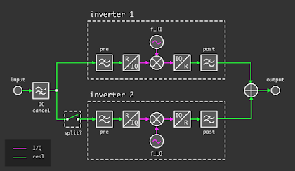
The oldest method of obfuscating the content of RF transmissions is scrambling. This is done using a set frequency value to invert the frequency of the input signal which creates a "clone" of the signal on a different frequency range. In other words , the signal is transposed to a different range and can only be decoded by a device using te same frequency offset and settings. Compared to other methods of protections , it is the most primitive as it can be easily broken and de scrambled. Even more complex scrambling methods like split-band inversion are also prone to de-scrambling.
De-scrambling voice communication for example, can be done by recording the signal we want to de-scramble using a program like SDR# and SDR capable of listenig on the specified frequency. After recording the IQ data we play it back using the same software and look for the inverse modulation. Depending on the modulation we can use either Upper or Lower Side band modulation to demodulate one of the two inverted modulations.
Frequency scrambler descrambling
Split-Band inversion works by adding one more carrier frequency which devides the spectrum into two equal but opposite parts and then combines them both into one signal. The most difficult part is finding the two initial frequencies before the combination happens.
There are automated programs that do this for us one example is "deinvert" by Oona Raisanen which can automatically monitor a frequency using an RTL-SDR and do the whole processes without any fiddling around. This also works with Split-Band Inversion but at a lower success rate. Deinvert On its own scrambling is effectively weak and only stops the weakest of malicious actors from listening and sniffing data. It needs to be combined with other forms of security.
Replay attacks are "simplistic" in nature as their end goal is to replay a transmitted signal to the targeted device. This could cause a device to respond to a message or command that was issued before for example, turning on and opening the garage door , turning off the light etc. These have become very common as they are easy to exectute on low-end devices such as sensors and IoT devices especially without any form of protection. Some mitigation strategies are to use rolling codes which are a type of encryption that can be used to prevent replay attacks. A rolling code works by using a hash function to create a unique code for each message. This code is then used to encrypt the message and then the hash function is used to create a unique code for each message. This is done to prevent replay attacks. cite
Denial of service Attacks are attacks that cause a device to crash or become unresponsive. They are very common in the form of flooding IMCP packets to webserver or devices to disconnect them from a network. It is one of the oldest and most common types of attacks. In the RF world it is known usually as jamming. To produce a jamming signal ,the jammer uses a signal generator to produce a continuous wave signal which is then sent to the target device. Usually a jammer will send out a stronger signal than the signal it is trying to jam effectively making the target device un-operational. In sound waves , we could cancel out the wave by transmitting an equal and opossite wave. In doing this, we cancel out the wave and the signal is completely cancelled there for the sum of the waves would be zero. This is not the same concept in the RF world as RF uses transverse waves which do not oscillate the same way as sound waves.
\int\mathbf{A}dV\cdot\int\mathbf{B}dV\neq \int\mathbf{A}\cdot\mathbf{B}dV=0
∫ A d V ⋅ ∫ B d V ≠ ∫ A ⋅ B d V = 0RF waves are always perpendicular to the direction of oscillation , thus when we examine their behaviour away from the their source of generatin we can conclude that they are always perpedicular. Therefore , it becomes very diffuct to jam a signal in the same way as sound waves as there are many factors taking place which could cause the signal to pass through.
Source https://www.physicsforums.com/insights/are-electromagnetic-waves-always-transverse/
Sniffing is one of the most common forms of RF attacks. Since there is no way of physically hiding an RF transmission , any transmission which does not use some form of encryption , hopping or scrambling faces the threat of being monitored by an unauthorized third party. In many cases using a proprietery protocol can also make it difficult for inexperienced unauthorized third party to sniff and decode the signal. This is because the protocol is not well known thus there are no presents available to decode the signal. In this case we can use a software to analyse the signal and determine its modulation , sample rate , bandwidth etc. In our case we will be using a software called Universal radio hacker which is a free and open source software that can be used to analyse the signal. Expanding , once a malicous threat actor managed to sniff and decode a signal , they can then use this information to perform a variety of attacks for example packet manipulation , replay attacks , etc.
A man in the middle attack is performed by a malicious third party by eavesdropping between two or more devices which are communicating with each other. Usually the attacker will try and mask themselves as the receiving or transmitting device that the other device has established a connection to. In doing so it allows the malicious threat actor to sniff and analyze the victims transmission without them knowing and also send back malformed packets which can be used to execute commands remotely . These can be in the form of forged ssl certificates , authentication keys for establishing secure connections or rogue wifi/zigbee/bluetooth devices which try to take control of a victims device. One of the first instances of a man in the middle was the decoding of the German Military's radio communication done by the Royal British Intelligence during world war 2. This was done using the Enigma machine which was used to decode the "encrypted" form of communication done by the German army.
Man in the Middle(MITM) attack usually happen on the communication layer . One of the most common forms of MITM attacks are spoofing attacks where the attacker takes on the identity of an authentic device trying to lure in the victim and steal their data.
[cite](MAN-IN-THE-MIDDLE-ATTACK: UNDERSTANDINGINSIMPLEWORDS) [cite](W. Kozaczuk, 1984)
For conducting our experiments we placed the devices in close proximity to our softwware defined radios. To eliminate the chances of interference we placed the devices in a large room with no other devices turned on in close proximity. Since our main receiving device the Hackrf is poor receive perfomance we did not have to worry about interference from device from other rooms. In the case of of testing our Weather Station sensors we used an RTL-SDR (SMART SDR) which was connected to a Raspberry pi using the RTL_433 decoding software. This allowed us to filter out any unwanted signals and capture only the ones we needed.
The Belking Nestcam HD (insert Information here)
By using sparrow WiFi in conjunction with our hackrf we deduced that the Belking NEtstcam was operating at 2.437 Ghz (Channel 6) , we could also monitor any clients that connected to the device or at least initiated a connection.
Using Sparrow WiFi we managed to use its inbuilt de-authentication function which uses both the hackRF and the computers wifi adapter. This produced valid results and disabled our devices from connecting to the camera directly . If any of the devices had been connected from before it would kick them off the network and disallow them from connecting back again .
Furthermore , we also used the hackRf on its own. By first moniting the frequency for IMCP Packets which we sent using our phone. Once we captured the packets we re transmitted the packets using the hackrf on the same frequency. This resulted in spikes latency from the phone to the the camera but no packet loss. This could be due to the following reasons:
-
The hackrf is does not transmit at a bandwidth large enough to cover the whole channel on its own. Even though the nest cam does transmit using only 20Mhz bandwidth , it is likely stronger than the signal being sent by the HackRF thus overpowering it.
-
The low power transmitted by the hackrf is not enough to completely overshadow the transmission of the Nestcam.
-
Wifi switches between modulation types there for if we are jamming using only one form of modulation we might only temporally manage to cause some disruption.
-
Even when using Universal Radio Hacker we where unable to decode any packets primarily because of the lack of bandwidth.
hackrf_transfer -r test.bin -f 2437000000 -s 20000000 -l 40
hackrf_transfer -t test.bin -f 2437000000 -s 20000000 -x 47
What we can take away from this is that we could possibly cause disruption of service by using a higher gain antenna and much stronger amplification of the signal. This would possibly disrupt the signal enough to cause substantial packet loss . In doing so , we could possibly attack the device from a larger distance which would make it almost undetectable without specialist radio equipment . More specifically some form of triangulation would be necessary to detect the direction of the signal .
Further testing has been done by also sending IMCP packets on a harmonic frequency of 1.2185 Ghz which has a second harmonic of 2.437 Ghz . Using the same method as above but just changing the frequency of transmission we observed that there a small increase in latency but not very substantial . This could be due to many factors result for example external interferance which makes it an unrealiable .
The Nest smoke alarm (insert info) uses both Bluetooth and wifi to connect to the internet and a nest hub. It uses Bluetooth 4.0 with a max transfer rate of 1mbps. It uses a modulation type of GFSK , operating between 2.402 ~ 2.480 Ghz. The channel spacing used by the device is 2 Mhz which makes it ideal for the hackrf to sniff at least one channel. Looking on the inside of the device we can see that it use a meandering mono-pole antenna with a gain of 0.29dBi and a maximum transmit power of 0.995 mW. The internal coax connections are done using a Sucoflex 104 which is a low loss , high stability cable with shielding acceptable up to 26.5ghz.
https://eu.mouser.com/new/huber-suhner/huber-suhner-sucoflex-104-microwave-cable-assemblies/
https://fccid.io/ZQAS30/Test-Report/Test-Report-BT-LE-2648525
By using sparrow wifi we could see that the device was using channel 6 for WiFi . We where succesfull in de authenticating the device using deauthetication packets from both the HackRF and the Wifi adaptor. Using only the hackrf we could see a small rise in ping . The same methodology as the previous testing was done .
hackrf_transfer -r test.bin -f 2437000000 -s 20000000 -l 40
hackrf_transfer -t test.bin -f 2437000000 -s 20000000 -x 47
Further more we have also sniffed the wifi packets using our WiFi adapter in monitor mode. By analyzing the packets we determined normal operation and nothing out of the ordinary was present. The only interesting result was that the device was continuously sending out beaconing packets at very small intervals.
By using the hackrf we have also sniffed part of the Bluetooth spectrum to capture the connection between the mobile phone and the Nest Device . Because of the lack of bandwidth available on the hackrf we cannot sniff the whole Bluetooth spectrum hence we only focused on channel 37 which was the most commonly used one. This resulted in multiple malformed packets being received with the only "useful" packets being decoded being the broadcast packet by the NEST device.
While sniffing the packets , there was no way for us to receive the handshake signal which could allow us to perform a replay attack . Even using the hackrf_transfer function to save the raw data and re-transmit them back we were unable to see any effect on the device or the network it was connected to . Furthermore using a harmonic freq of 1.2185 Ghz we were able to slightly increase the latency between the device and other device but not substantial enough to cause any issues.
The hive hub is a zigbee device coordinator used to connect and control multiple zigbee devices. The device it self transmits using an RF6555 CHIP which is capable of transmitting both WIFI and Zigbee with a maximum transmission power of 18dbm. The chip also has an integrated Low noise amplifier for greater reception and transmission . For the device to start transmitting and receiving Zigbee packets , it requires an account to be created on the Hive website [cite] , this posses a potential threat , if the Hive service would at some point become obslete it would render the device useless.
inFactory sensors are widely used sensors which can be found in many weather stations. Many of these weather stations either have built in functionality to send data over the internet or use an other thirdparty device to do this for them . They usually operate on 433.920 Mhz using FSK modulation which send out packets to neighbouring monitoring devices which display the data. This data is sent using an unencrypted signal which can be decoded using the rtl_433 software. Many IoT enthusiasts have used rtl_433 to decode the data and perform analysis on the data.
To aquire our data we used rtl_433 to decode the data and perform analysis on the data. We were able to see that the data was being sent out using a frequency of 433.920 Mhz. This frequency is used by the COWP weather stations to send out data. We used the following command to decode , store the signal and later perform analysis on the data using Universal Radio Hacker. The flags used in the command are as follows:
- -d: Device number
- -R: Device ID (at specified in rtl_433 wiki)
- -a: Analyze mode 4
- -A: Pulse Analysis
- -S: Store all raw signals
rtl_433 -d 1 -R 91 -a 4 -A -S all
Many of these weather stations send data to the internet which are used by community driven services. This data is then used to create graphs and send out notifications to users. The data is then stored on the internet and can be accessed by anyone. This is a potential threat if the service becomes overun by malformed information which could render the information useless. One such service is the Citizen Weather Observer Program (COWP) which is a community driven service which provides weather data using community driven weather stations. This information is made available and used by weather services and homeland secuirity. The COWP is a great example of a service which is not only used by the community but also by the government. COWP lists on their website that they are used by over 800 different government and non-government organizations .
Many of the sensors are housed in thin plastic casing with little or no shielding from the elements. Furthermore , the circuit board itself has minimal protection from external RF interferance which makes it easy to Jam and break the connection bewteen the screen and the sensor. To achieve this we sent out a signal using a HackRF irrelevant of modulation mode as it would still be more powerful than the sensors internal amplifier. Although we were able to jam the connection between the HackRF and the sensor , we could take this a step further and use a handheld tranceiver and transmit a carrier wave on 433.920 with more than 1 watt , this could potentially jam multiple devices on the same frequency and at a much larger distance.
The simplistic nature of the protocol used aswell as the lack of authentication and encryption makes it quite easy to replicate the signal. Furthermore the protocol is very simple and can be easily modified to send out a different message. This attack is very effective as it requires no knowledge of the protocol and can be easily replicated. By capturing the packet using Universal Radio Hacker we were able to analyse it and deconstruct it in a readable format . This was achieved using six different samples if the packet to allow us to cross reference between them and also detect any changed that might be present in the packet.
While trying to reverse engineeer the packet we deduced that the first 12 bits are used as a preamble to syncronize the local time with the remote time. The next 4 bits are used to encode the synchronization and the remaining bits are used to encode the message being sent. The packets are being sent in 30 second intervals which gives us a 30 second window to send out a message. The message is sent out using the same protocol as the sensor would send it out and is intepreted by the sensor. The message is then decoded and displayed on the screen.
Building on our replay attack and the decoding of the signal using URH , we can further try to modify the packets using signal generator packet. After changing values randomely in the data part of the packet we were able to send out a modified packet which was decoded by the sensor and displayed on the screen. This was achieved by sending out a modified packet with the same preamble thus allowing the receiver to identify the signal .
https://github.com/merbanan/rtl_433
https://fccid.io/2APN5SNZB-02 https://www.ti.com/lit/ds/symlink/cc2530.pdf?ts=1627450920062&ref_url=https%253A%252F%252Fwww.google.ru%252F
The Sonoff SNZB-02 is a small Temparture / Humidity monitor that operates using the zigbee protocol . It uses a small internal PCB antenna with a maximum power of 3mW or 4.58 dBm . This achieved using a cc2530 chip which is a very small and low power radio chip . The device uses a standard 2.4 Ghz RF frequency and uses a GFSK modulation which is a very low bandwidth and low power modulation . The device itself is housed in a small plastic casing with minimal shielding from other forms of RF interference . This device is very small and can be used in a small space like a room or in a small space like a room. The device itself will send out a beaconing packet alerting any receiving device of the current temprature and humidity of the area.
"insert picture here"
The device sends out data using metric units while also sending telemetry for monitoring the health of the device. The SNZB-02 sends out a packet containing :
- Temptrature in Celcious with a resolution of 0.01 degrees
- Humidity in % an accuracy of 0.01
- Battery Level from 0 to 100
- Link Quality from 0 to 100
- Voltage in millivolts
The device itself suffers from a poor design element of not having a way to turn off the device . This means that if the device is left on for too long it will continue to send out packets and consume power but also the positioning of the pcb antenna will affect the signal strength .
As we can observe the pcb antenna is located next to the cc2530 chip on the very edge of the board. Although there is very little room for improvment of the board design we can still improve the design by moving the pcb antenna to a different side of the board or even adding an IPX connector to add a small wire antenna . This would allow us to reduce signal loss of the device but also increase its transmission range. This is importart as a lot of the devices are not able to receive signals from a distance greater than a few meters. This has the benefit of reducing the chances of a rogue device being able to intercept the signal.
Expanding on this dilema , a very low skill attack of just sticking some aluminium tape on the side of the device could potentiall block the signal from being received by the coordinator.
Using Universal Radio Hacker we where able to capture the signal of the device but due to the nature of the Zigbee protocol its use of frequency hopping we are unable to succesfully replay the intialisation packet. This means we are unable to connect to the coordinator using our hackrf. Furthermore , just like bluetooth the low bandwidth used by the zigbee protocol means that we are unable to replay the entire packet. We were able to capture part of the packet but not large enough to decode or analyse it . Even though we took this into account , we managed to breifly replay the packet back to the device when it was listening channel 11. This was only momentary and only happened for a few seconds after that we were unable to do the same thing again for some time.
Like most devices it starts sending a beaconing packet on channel 11 (2.405 Ghz) . Channel 11 is the channel most frequently used by devices in the 2.4 Ghz band to initiate the syncroization of the local time with the remote time. This channel is also used by the Zigbee protocol to send out the beaconing packets. But since the Zigbee protocol is designed to use frequency hopping it becomes difficult to actual jam the channel. But after further investigation we manage to Jam the signal using SDRANGEL using its 802.15.4 module. By transmitting a random Zigbee packet we were able to stop the receiver from gathering telemetry from the device. It should be noted that this only worked after syncronizing the device with the coordinator. Furthermore , it should also be noted that the hackrf has a much greater transmit power than the Sonoff device which means that we were just overlapping the signal. We used a bandwidth of 10 Mhz just enough to jam the channel and the one next to it , this allowed us to stop the device from hopping over to a "free" channel".