Enhancement: Adaptive Pressure advance #5609
Conversation
Reduce the frequency of requested PA changes by introducing a "state" variable.
Implement user toggle for adapting PA for external walls for overhangs
|
Awesome |
Want to see how it performs. I have 2 use cases for this:
Number (2) has been disproven as a benefit as klipper has a micro stutter when changing PA, causing the reverse effect. I am now testing (1) as the micro stutter shouldn't matter when transitioning features anyway as you're starting to print from a stand still anyway. Hopeful that this will be the major use case but will see following testing. If (1) is also disproven then I will shelve the feature as not needed and having an approximate PA being good enough for most cases. I'll be updating the original post with my test results, but always welcome community testing as I only have 2 printers :P |
|
This is awesome! Do you use same accel for all the features in your tests? |
Nope I'm using varying accelerations as below: but I guess my accelerations are not sufficiently different between perimeters to show the effect of acceleration on PA. The only place I go high is internal solid infill. The rest are reasonably conservative (in order to remain within the klipper input shaper envelope). The above PA profile was tuned for 3k accelerations. From the test I've done, higher acceleration does indeed affect PA but more likely than not it's a linear correlation. So what I suspect is happening in my test situation is that the faster speeds use lower PA anyway and that is good enough to prevent issues showing on the internal solid infill which also uses very high accelerations. |

|
I wonder if this would also improve performance for scarf seams due to the change in speed and flow rate. Does the changes in this PR affect scarf seams? If so, I'll try some tests targeting scarf seams :) |
|
So... Digging a little more: https://klipper.discourse.group/t/pressure-advance-smooth-time-skews-pressure-advance/ From Kevin: "It may be possible to come up with an alternative smoothing system [the smooth time approach] to reduce the amount of over-extrusion during slow speeds. (Possibly by giving greater weight to the desired extruder position at low toolhead speeds.) It’s not immediately clear how to do that though." "It seems an acceptable (smooth time) value is dependent on acceleration - the higher the acceleration the lower the smooth time should be in order to get acceptable results." So it appears we actually have a double whammy and this (the effect of smooth time) is what we are compensating for. I may extend the feature to also consume an acceleration profile for a specific speed value and use the two curves to interpolate between. For reference I have the smooth time set to 0.01 on my printer and this may be the reason why the curve is not ridiculously steep or not as visible as variations between different feature accelerations More research is necessary..... |
No it won't as we must not be changing PA during a feature being printed as this causes proven scaring. So its a no go for this. |
|
I'm also thinking it might make more sense to use volumetric speed instead of print speed here. At the end of the day, it's all about predicting and compensating for the pressure inside the nozzle. Wouldn't volumetric speed be more precise? If it works, it could make line width, layer height, and even nozzle size agnostic! |
|
Test prints with a 10k acceleration target done. At 50mm/sec there is no difference between the 3k and 10k acceleration PA test. At 100mm/sec the optimal PA drops from 0.029 to 0.026 At 150mm/sec the optimal PA drops from 0.026-27 to 0.022
So there is for sure another correlation there. |


|
For volumetric speed I need to do PA tests for the same speed and acceleration using different layer heights - that should keep the time dimension constant (speed/acceleration) while only looking at the flow rate. To be honest I'm still trying to triangulate where that non linearity is happening from - if we understand that then we can model it. So far candidates are: For number (2) this is interesting. I would expect that
However from my experience with a 0.25 nozzle, I use a PA value there of 0.048 compared to the avg. of 0.030 or so for the 0.4 nozzle. Which makes sense as higher inherent pressure needs higher PA. However look at this part of the curve here:
Maybe the reason it is flattening is because of the increase in pressure reducing the effect of smooth time on the needed PA compensation.... And maybe the reason the curve isn't flattening as much for higher accelerations is because the smooth time effect is larger than the pressure non linearity? What I can tell for sure using experimental data so far:
We need more tests and I need more brains for this!! |

|
So I’ve run a set of PA tests with varying flows (using different layer heights, keeping speed and acceleration constant) and there definitely is a correlation - lower flow needs higher PA or it looks that way. It’s getting a bit late here so I’ll post results tomorrow |
|
I ran a quick and dirty test, even though my printer is probably not the main audience for this feature as its a slightly modded ender 3, and I can see some marginal but promising results. My inner and outer walls have smaller/thiner gaps in between each other, there are smaller pinholes for my internal solid infill, and my initial layer is more consistent and no longer has a flattened out edge for the circle that makes the hole of the orca cube. I did also notice slightly worse overhang performance like you already mentioned. |
You shouldn’t have a difference in overhang performance as I’ve disabled the code that was causing the Pa to change before and after an overhang. Curious to what you’ve seen so I can fix it - any chance of a before/after pic for the overhang region? |
|
Good morning everyone! A bit of an update on flow vs PA. Below is a graph plotting the different PA values as a function of flow rate. Volumetric flow speed based changed using variable layer height: A couple of observations:
Community ask: It would be great if someone with a 0.6 nozzle could verify that their PA is correlated to nozzle size inversely. ie do you use a lower PA for a larger nozzle (with similar geometry) or not? What has the community observed? PS. the only reference I've found related to PA and nozzle size scaling was here: https://www.reddit.com/r/klippers/comments/14dhj2y/comment/joq929v/?utm_source=share&utm_medium=web3x&utm_name=web3xcss&utm_term=1&utm_content=share_button and the user does indeed say that there is an inverse relationship -> larger nozzle -> lower PA which would validate the above results. Converting the code to base the extrapolation on flow is a piece of cake (the interpolator doesn't care what values you put in anyway), so once we have some positive confirmation that this trend continues with larger nozzle sizes (reducing PA the larger the flow rate) I will convert the code from speed based to flow rate based which would have some very cool side benefits if the correlation holds:
|


|
I use significantly lower pressure advance with 0.6mm nozzle compared to 0.4 when printing. I mainly print PETG, and 0.6mm nozzles have a PA value of 0.012 while for 0.4mm it's 0.045. So seperate PA curves for each nozzle size is probably still needed, probably due to the viscosity of PETG so it has a much harder time going though 0.4mm nozzles? |
It's probably because I didn't spend much time making sure that the PA values were the best ones to use and using an old and crappy filament. I'll do some more through tests once I have some good filament. |
|
New build is up. Found a rare bug which impacted seams if you had enabled wipe before external perimeters - this is now fixed. Also it’s up to date with the latest orca mainline branch. |
|
I think it might be caused by how pressure advance is calculated. Because when extrusion slows down, it effectively retracts, then it transitions to outer walls, with higher PA, then accelerates. I think due to higher PA more material is pushed out of the nozzle than retracted in? |


|
I;ve broken something on this build - please hold off :) |
|
|


|
@GromovPeter I've only tested it on objects with 0.2mm and 0.1mm layer height and it worked, making both types of layers have sharp corners. For your case I think it requires more precise calibration.
|

If I print fix layer hight it looks perfect. But variable layer height I think it change Flow and pressure advance and corners going very different depends of layer height |

|
OK bug fixed. @Ataraxia-Mechanica the changes wouldn't help you with your specific case - it was only when wipe before external was enabled and specifically on overhanging regions, so it wouldn't trigger this issue with what you saw I'm afraid. I really wish I had your printer to figure out what's going on :( Looks like I need to do some petg testing... Could you post the project file for your test print? I'd like to run it through my printer, in case I'm missing something |
This feature will change your PA if you change your layer height. But your case looks very extreme - I've never seen anything so pronounced with variable layer height, with this feature disabled :S So something else is going on, and I'd suggest trying to trouble shoot that before delving into this feature. Potentially your extruder struggles with the increased pressure from the lower layer height. But still it shouldn't be like this. Maybe your baseline PA value is way off? |
|
@GromovPeter At least it looks like the thick layers are having too high PA values, so it follows the higher flow having lower PA behavior, so this PR should improve the corners. I think the value is just too high in general? |
I have enabled pressure advance in meterial. 0.05. I think it must be constant and not changing with different layer height. |
|
@GromovPeter You need to use the calibration button and select pressure advance, then test out different value under different flow, then fill it inside the new setting inside the filament. The newest build isn't ready yet, after it finishes, you can do this: |

|
@Ataraxia-Mechanica I've taken a look at your project file - firstly omg aren't you making good use of the plates feature :D Secondly, a couple of things to try:
ERS disabled:
So maybe run one test with all three recommendations. ERS disabled, 3 perimeters and 0.46 line width for external and internal perimeters and post a picture? PS. Please use the latest build |


|
The surface quality with 0.46 width looks so good. I was using orca wrong this entire time :( |
post a pic :D Did you do all three suggestions or just the line width? Would help troubleshooting and also learning :) |
|
All 3 suggestions. 3 walls static > 2 walls static > 2 walls dynamic > 3 walls dynamic, for some reason. With dynamic PA on, the seam also splits up into 2 parts. Guess the extra material builds up more with 3 walls and dynamic PA? PA also needs to be a bit higher it seems. |

|
Your PA for sure needs to be higher... |
|
Also when using dynamic PA, as the value is more aggressive for your external perimeters this would lead to the seam gap being potentially more pronounced. You can set your seam gap to 0% instead of 5% I think you have now. This will close the seam more tightly. Finally with 2 walls the outer wall is printed first, immediately after a retraction and travel move. This usually leads to inconsistent seams as the nozzle has ever so slight time to depressurise and also has to precisely control the deretraction process which is inherently variable (extruder slack and play, filament grip, resistance in the tube etc) Compared to printing with 3 walls, the seam starts immediately after an internal perimeter is printed. So the travel from the inner to the outer and then back inner is tiny, so no loss of pressure. And usually there is / shouldn't be any retraction there as well. |
|
Also, in both cases, the PA of outer wall is 0.038, so I don't think it's caused by outer wall PA? By the way I think you should make what you told me into a tutorial. More people probably have set the extrusion width to exactly the nozzle width. |

|
That is the wipe move. Set your min distance before retracting to 2 or 3mm to avoid retractions when moving between perimeters on inner and outer inner ordering. Especially as you appear to be using staggered inner seams |
|
But by using travel distance threshold, the wipe on outer wall disappears first, then the wipe of inner wall disappears. |

Yeap the wipes are not necessary over small distances... The nozzle doesn't have enough opportunity to ooze so you're causing more harm than good by retracting, wiping and unretracting. I would set to 3mm if I were you, especially as your travel speeds are 500mm/sec and accels at 25k - there is zero opportunity to ooze over 3mm with that speed ;) Also I've noticed you're using a negative extra length on restart. This, I suppose, was because your filament oozed and you wanted to get better seams. But with the right PA, this may be causing unintended consequences, like the seam gaps you're seeing as the nozzle isn't fully primed. If I were you I'd go for inner outer inner, 3 walls, no extra length on restart, 3mm distance before retraction. In any case I'm attaching you my profile so you get some ideas :) And you may need to up your PA as your non seam corners are still bulging out I'm using a 2.4 350, so not as fast as yours :) But even with slower speeds this works very well |
|
Oh, that was just from a slightly older file. All the tests done today was with 0 extra length. Currently I'm using 0.045 PA and it looks good. By the way with wider line width the printer seems to be much better at bridging, perhaps because lines wasn't stretched? Thank you for diagnosing my issue today, never realized my profile was wrong. |
|
@Ataraxia-Mechanica stefan from cnc kitchen has a decent article on line widths here:https://www.cnckitchen.com/blog/the-effect-of-extrusion-width-on-strength-and-quality-of-3d-prints take a look at my profile - maybe you find other variances too that are of interest ;) to not “pollute” the pr just reach out to me over discord and we can chat there too :) |
|
So new push completed - have enabled adapting PA on fully overhanging perimeters as shown below. Highly experimental and may end up reverting it as it is unproven whether this is doing more harm than good but pushing out to testing.
@lookypanda would you mind cross checking that I have not introduced any regressions against your "tricky" models above if possible? @Ataraxia-Mechanica same here if you haven’t run out of blue petg yet 😂😅 All, Dont think I'll do any more updates to this for the coming week or two as looks like work will get a bit crazy but please do let me know if you find any issues. |


How picky are you about getting your PA tuning absolutely nailed for sharp corners but also no gaps between perimeters? This feature aims to bring PA tuning closer to perfection by reducing the compromises made when picking a single ideal PA value. The benefits are not earth shattering, but if you are picky about print quality, they are there.
I will leave this PR at this stage of development for now and would love your feedback and observations. It works, doesn’t appear to be causing any bugs, it’s just not fully optimised code wise yet
This PR is a long read but hopefully it will be useful :)
EDIT: Feature has been revamped to cater for accelerations and volumetric print speeds together, creating a 3 dimensional PA model that is used to derive the most appropriate PA against both different accelerations, print speeds, layer heights and line widths!
Testing is needed to demonstrate value and any adverse effects and whether we can mitigate them.
The description below has been updated with the revised workflow.
Feature Description and approach
What I and others have noticed is that the PA value needed to avoid artefacts is less the faster you print and the higher the print acceleration is. (see credits in the end and user submitted test results in this PR).
To demonstrate this I've run a series of tests from 50mm/sec to 200mm/sec at 3k acceleration, 0.2 LH and 0.015 and 0.005 smooth time.
From left to right at 50-100-150 & 200 mm/sec and 200mm/sec at 0.005 smooth time with constant acceleration at 3k.

Next I run a series of tests for the same speeds (50-100-150mm/sec) with constant acceleration at 10k
What this means is that we never get ideal PA values for each print feature. We can tune PA for a faster print speed but compromise on corner sharpness for slower speeds or tune PA for corner sharpness and deal with slight corner perimeter separation in faster speeds. Same for accelerations.
This compromise usually means that we tune for an "in between" PA value between slower external features and faster internal features so we don't get gaps but also not get too much bulging in external perimeters.
In this PR I am aiming to address this limitation of the current way to use Pressure Advance by proposing a completely different method of setting pressure advance.
In this PR we are enabling the slicer to model the extrusion behaviour for different PA values vs. volumetric flow speed vs. accelerations and use that model to emit the best fit PA for any arbitrary feature used in the print process.
As a bonus, depending on the profiles created it may mean that you only have to tune this feature once and print across different layer heights and different nozzle sizes with good PA performance.
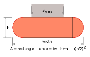
What is volumetric speed?
In this model we are using the volumetric print speed - this is basically calculated as
Luckily Orca displays the volumetric speed in the sliced model so there is no need to do any calculations. It's called "Flow". This is proportional to the print speed as well as layer height and line width. So by keeping the layer height and line width constant in testing we can vary the print speed to get the PA results for different flow speeds.
PA testing workflow:
Screenshots of the workflow:
Step 1: Enable "Enable adaptive pressure advance (beta)" in the filament section

Step 2: Run the above PA tests for your filament
Step 3: Add them to the box, one test at a time - PA value,coma (,),tested flow speed,coma (,), tested acceleration. Save the filament profile. Make sure the value set in the pressure advance box above the options is a reasonable default as it's still used if the model fails for any reason.
Step 4 Add a model & slice. Observe the PA values changing when there is a change to the extrusion role (i.e. when printing internal perimeters and then going to external, when going from perimeter to bridge, etc). The PA value is then calculated based on the upcoming feature print volumetric speed and acceleration.
For example:

All features having the same / similar volumetric speed but different accelerations
Now with all features having the same acceleration but drastically different volumetric speeds:

Now for a combo of both - notice how the fast accelerating and high speed internal sparse infill has significantly lower PA than the walls which are slow accelerating and printing slightly slower too.

Now lets try a lower layer height:

PA set to 0.029 for the internal wall vs. 0.026 before :)
Why create a model instead of simply 4-5 PA pairs?
An alternative approach would be to submit a list of values (PA & speed) and let orca use these if the printed feature speed matches exactly.
The approach in this PR is more flexible. If the values match exactly, the exact PA will be used (due to the choice of regression model there is no deviation from the provided values). However, if they don't match exactly, because the user has picked a different speed and acceleration than the one PA was calibrated to, this approach will still estimate a reasonable PA value to use, granting more flexibility.
What interpolation model to use?
PCHIP is the preferred model as it has zero delta error from the submitted values (ie there is no deviation from the submitted PA/speed value pairs and the model response). It also will always return a value that is never higher than a linear interpolation between the two consecutive data points. This is important, as we don't want unpredictably higher values than if a straight line was drawn between the two samples, which can happen with spline/cubic etc modelling.
A set of models that were run through fitting is below for my initial tests:

We can indeed see that PCHIP is the preferred model as it doesn't over shoot from the general data trend, always returns the given PA value if the speeds match and smooths out the "curve" between the sampled points.
Preliminary conclusions and testing next steps:
It appears that adaptive PA can marginally improve print quality by better matching PA to the printed feature speed and acceleration. The largest benefits come from
This feature will NOT benefit the widest audience as the standard implementation of PA is meeting 95% of user's expectations. However if you want the last 5% it may be for you.
It will also benefit users that have a less constrained filament path between the extruder and the hot end - as this would typically require higher PA values hence the delta would be amplified. In addition, anyone still using a Bowden printer should see a benefit as seen in the links in the credit section below.
However to really notice the difference your printer needs to be spot on - EM, extruder in good mechanical health and a good design and your printer mechanics working well.
As I am a big fan of developing features that I will be using daily - from my side this is something that I will enable across all my filaments. The benefits are marginal, but they are there. As I will be daily driving this I'll let you know if I observe anything further.
I will leave this PR at this development point for now and would love your feedback and observations.
Status & ToDo:
MVP development
Testing:
Known potential issues:
Refactoring and tuning
Credits:
Inspiration for this feature was taken from the below community conversations and implementations.
Testing:
Hypothesis 1 (and the main use case) - Prove or disprove whether adapting PA when printing using widely different speeds would result in sharper feature edges.
When printing infill with 250+mm/sec, internal walls at 200+mm/sec and external perimeters at 50mm/sec the PA needed to ensure sharp feature edges with no perimeter gaps is different (as illustrated from the PA tests above).
Therefore the hypothesis is that varying the PA based on feature speed would result in sharper edges with less perimeter gaps and remove the existing potential compromise.
Testing profile below for my Voron 2.4 350. Using poly terra grey PLA as its the most revealing filament I have :)


With adaptive PA enabled:

Testing for wall artefacts on overhangs
Test shows no artefacts where the slowdowns begin. That is expected as we are not changing the PA in those regions. However there is ever so slight bulging after the corner of the overhang, which could be attributed to needing even higher PA. However check Hypothesis 2 below for relevant test and results.
Testing for corner performance


This looks exceedingly good to me. Absolutely no bulge in the corner. Just the smooth rounding caused by the SCV of 5mm/sec
No cover perimeter separation at all.
Testing for seam performance

Again this looks excellent. Absolutely no bulge at the seam.
Testing for top surface performance

Again this looks excellent. Absolutely no gaps, pinholes, under extrusions or over extrusion.
Testing for solid infill performance

Again very good - very smooth and connected to the perimeters. My overlap for internal solid infill is at 10% so there are some expected pockmarks.
Testing With Adaptive PA disabled and PA set to the value that gives good corner performance at slow speeds (50mm/sec)
In this "before" test I've disabled adaptive PA and set the static PA value for the filament to 0.04, which gave me the best corner performance when extruding at the external perimeter speeds.
As expected that PA value was too high for the faster internal features resulting in the typical issues you'll see happening from it.
Testing for corner performance


External corners look excellent; however slight perimeter separation on the faster internal perimeters. Typically this won't be visible to the outer shell as you can "hide" it using one wall top and bottom surfaces; however it is not performing as expected and won't pass the quality mark for something like PIF.
Testing for top surface performance / solid infill performance


We can clearly see that the PA is too high for the faster internal solid infill here as there is under extrusion when the solid infill begins/ends
Seam performance and overhang performance


This is unchanged as expected as we have tuned the PA for the slower external perimeter
Testing With Adaptive PA disabled and PA set to the value that gives good corner performance at fast speeds
The PA value for the below test was set to 0.026 which is the correct value when printing faster features in the range of 150-250mm/sec. This would be the value I would typically select when tuning the printer without this feature as it gives absolutely no perimeter gaps and a reasonably good external surface performance.
Observations:
So this is an interesting one.
Corner performance:

Admittedly this is very good and I would consider this as close to excellent too.
However upon closer inspection you'll notice the below:

The static PA test starts taking the corner later compared to the adaptive PA. This is incorrect due to the SCV being applied uniformly. You'd expect a perfect radius here. However this may give the appearance of a sharper part but the corners will not be uniform leading into them and moving away from them. They will always be sharper going into the corner than coming out of them, if that makes sense.
So adaptive PA takes the win here, but marginally. You can feel the difference in your hand but honestly, both parts are acceptable. Again, how picky are you about your PA....? :)
Seam performance:

Again another interesting test here - again the performance on first look appears great (and it is!).
However what you'll notice if you compare the two seams side by side is that the adaptive PA has an ever so slightly better controlled seam where the arrow is.

Wall printing performance:
This I did not expect and we need to do more tests to verify this or disprove it. It appears that the adaptive PA gave a slightly better wall finish to the print, coming out from an overhang. This may be expected as the extruder is pushing out now closer to the correct volume of material compared to the speed its printing so there is less random over extrusion when accelerating? All in all the surface finish appears improved with the adaptive PA.
Hypothesis 2 - Prove or disprove whether adapting PA when transitioning from printing external walls at the external wall speed to a (slower) external wall overhang region would show any benefit by having the right PA for that overhang speed.
When printing an external wall surface, there can be significant variation in print speed when transitioning from a fast print move printing the external walls, to a slower print move printing an overhang region. This would mean that the overhang is printed using a sub optimal PA (too low) potentially causing corner edges to slightly bulge.
Test performed:
Printed the orca cube at 150mm/sec external perimeter speed and slowdown for overhangs enabled, going down to 20mm/sec for the 75-100% overhang region.
Print results below:

Conclusion:
It appears that when changing PA when transitioning from a faster speed to a slower speed for an overhang causes feature bulging. This is the opposite of what is expected as the PA emitted is higher than the regular external wall PA. The assumption was that this would cause the opposite and "tighten" up the overhang regions.
After analysing some slow motion footage of the extruder I can see an ever so slight movement stop that is barely visible to the naked eye but is enough to cause that slight feature deformation.
This means that:
I have left this feature available for testing; but most likely it will be removed in the future unless tests to the contrary are provided.
After these results I have hidden this option in the GUI as it has adverse effects. If anyone wants to test this reach out.
Hypothesis 3 - Prove or disprove whether adapting PA when transitioning from printing a faster perimeter to an overhang perimeter or bridge could improve bridging performance and post bridge extrusion consistency
To be tested.
**Hypothesis 4 - The PA behaviour is tied to volumetric flow speed instead of print speed exclusively.
Initial tests seem to indicate that there is a positive correlation between flow speed and PA. The feature has now been revamped to use the volumetric flow speed instead of the print speed.