Example 03: Multiplexed signal readings

Additional documentation for an example supplied with the KeyDetector library that demonstrates how to encode digital signal into single analog line and decode it using library.
This is more of a real life example. Imagine you want to control your project with wireless controller, such as, for example, PS3 DualShock 3 or Navigation Controller. You decided to use USB Host Shield Library 2.0 with compatible USB Host shield for your Arduino and a Bluetooth dongle. There are quite a bit of documentation out there on how to achieve that, and a basic example that comes with USB Host Shield Library 2.0.
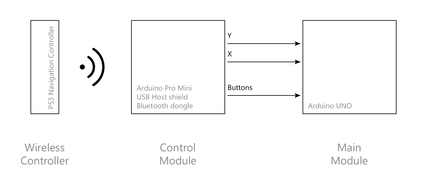
Now, what if for some reason you decided to divide your project into two parts (or modules): Control module, responsible for interaction with PS3 controller, and Main module, which will hold primary logic of your sketch? This may be an option in case, for example, when there are simply not enough space left for your own primary sketch after including USB Host Shield Library 2.0. Or you just prefer systems comprised of modules, which can be upgraded independently from one another.
So you’re left with two modules that need to be somehow connected in order for Main module to receive data from Control module. If you find yourself in a situation with limited pin budget, you may want to multiplex control signals from digital buttons of your controller (connected to Control module) into single analog line. That way you’ll be able to connect modules with (almost) only one wire (not counting power and GND wires as well as any other analog signals you may want to transmit from the controller, such as stick coordinates).
In this example we’ll see how to encode (or multiplex) digital signals into analog signal as well as how to decode (or demultiplex) it back on the receiving end using KeyDetector library. Additionally we’ll transmit signals form analog stick of the PS3 controller with the use of PWM to analog conversion.
Note: in order to proceed with this example it’s highly recommended that you’ll get familiar with how to use USB Host Shield Library 2.0 and how to set it up to operate with Bluetooth connected controller.
- Arduino equipped with ATmega328 controller (UNO, Pro, Pro Mini, etc.); Arduino Pro Mini (ATmega328/3.3V/8MHz) was used in the example
- USB Host Shield compatible with aforementioned Arduino; USB Host Shield for Arduino Pro Mini was used in the example
- Controller (PS3 DualShock 3, Navigation Controller or compatible)
- Compatible Bluetooth dongle; HAMA H-104890 was used in the example
- Arduino UNO or compatible
- Two 10kOhm resistors
- Four 20kOhm resistors
- Two 1MOhm resistors
- Two 100nF capacitors
First, lets assemble Control module. Attach USB Host Shield to your Arduino equipped with ATMega328 controller. Arduino Pro Mini was used in this example, however it may be similar or compatible board. Restriction to use ATMega328 is essential because of specific direct port manipulation used in the example. Connect your controller via Bluetooth to USB Host Shield (refer to appropriate guides on how to do that) and make sure your set up is working (use basic examples that come with the USB Host Shield Library 2.0 for testing). PS3 Navigation Controller was used in this example (DualShock 3 should also work without the need for altering the source code).
This set up will provide us with the way to detect presses of controller buttons and get coordinates of its analog joystick. Now we need a way to transmit this data to the adjacent Arduino, which forms Main module. One possible way to do this is to use multiplexing.
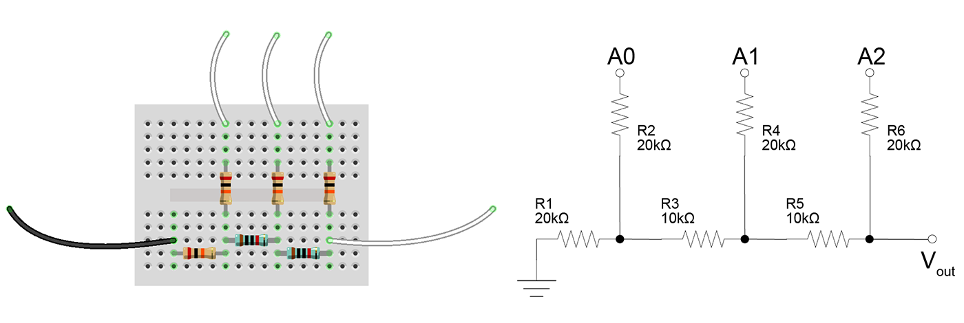
Multiplexing here is essentially encoding digital signals that come from different buttons of the controller to the different levels of the analog signal, that can be transmitted through a single wire. In order to achieve that, we need a way to perform digital-to-analog conversion. We will construct a simple R-2R resistor ladder DAC for this matter. For the sake of simplicity lets assume we need to detect keypresses of the following buttons: D-pad (top, right, bottom, and left arrows), X key, O key; six buttons in total plus one additional signal level for the state of no buttons pressed. Minimal resolution of the DAC that will allow us to encode that many signal levels (namely seven) equals 3-bit. In theory that gives us the ability to encode as many as 8 different levels. So we got ourselves one spare here.
As per Wikipedia:
An R-2R Ladder is a simple and inexpensive way to perform digital-to-analog conversion, using repetitive arrangements of precise resistor networks in a ladder-like configuration.
3 digital bit inputs (A0, A1, A2) are switched between V=0 (logic 0) and V=Vref (logic 1) levels, where Vref=3.3V in case of Arduino Pro Mini board used in the example. The R-2R network causes these digital bits to be weighted in their contribution to the output voltage Vout.
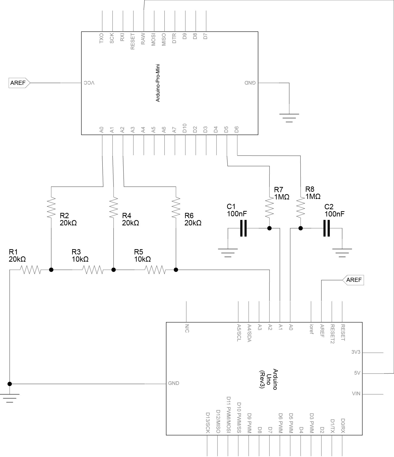
Our DAC comprises of set of two 10kOhm and four 20kOhm resistors, connected as follows:
Note on tolerance (accuracy) of the resistors. Using resistors with 1% inaccuracy should suffice for the 5-bit R-2R resistor ladder DAC, and resistors with inaccuracy up to 5% - for 3-bit DAC (such as one described here). However, should you find any of the signal instability (such as false readings or signal ripple) try to increase
analogThresholdvalue submitted toKeyDetectorduring initialization.
When writing this example 20kOhm resistors with 5% tolerance and 10kOhm resistors with 1% tolerance were used. Actual measurements showed that 20kOhm resistors had resistance of around 19.7kOhm and 10kOhm - around 9.9kOhm. Both measured values fall well within specification. More so, taking value of 9.9kOhm for R, 2R equals to 19.8kOhm, which is really close to the actual measured 19.7kOhm value (more specifically being within 0.5% tolerance). That is well within recommended tolerances for 3-bit R-2R DAC.
More details on accuracy of R-2R resistor ladders can be found on Wikipedia.
In the sketch we will set the values of DAC input bits A0, A1, A2 according to the button currently pressed on the controller.
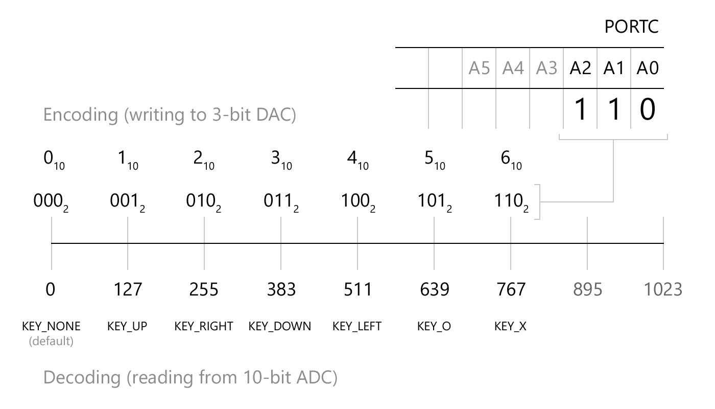
E.g. Up button will correspond to pin states (A2,A1,A0)=(0,0,1), effectively presented as binary code 001 (with A0 being the least significant bit, LSB; and A2 - the most significant bit, MSB). Similarly, Right button will correspond to code 010, Down - 011, etc.
Tricky part here is to set all three output pins of Arduino, which connected to input pins of DAC, simultaneously, to prevent false codes being encoded during pin state change. Using standard digitalWrite() routines for each of the pins won’t suffice. So we’ll use direct port manipulation instead. Connect A0, A1, A2 input pins of DAC to A0, A1, A2 pins of Arduino Mini Pro respectively. You can set these pins by writing to three lower bits of PORTC register of ATMega328 - that means that we can write our conceived earlier binary codes directly to PORTC, e.g. PORTC = B000000001 (or PORTC = 1) for Up button, PORTC = B000000010 (or PORTC = 2) for Right button, etc.
Output analog signal Vout of the DAC is then supplied to the standard analog input pin of receiving Arduino (our Main module), which is equipped with 10-bit ADC. The value is then decoded using KeyDetector library to restore the state of currently pressed button.
Relation of A0, A1, A2 pin states, binary codes, PORTC values and output value of the DAC (supplied to the 10-bit ADC of receiving Arduino) is shown on the following diagram:
To transmit values of the analog stick (the only stick available on the Navigation Controller, or the left stick of DualShock 3) we will use two separate wires: one for X coordinate of the stick, the other - for Y coordinate. Arduino Pro Mini is capable of outputting PWM signal only. In order to convert it to analog form, that will be later fed to the analog input pin of receiving Arduino, we will use Low-pass RC filter, comprising of single 1MOhm resistor and 100nF capacitor.
Values of the resistor and capacitor were calculated using online PWM conversion tool given the output frequency of the PWM-enabled pins 5 and 6 at 980Hz for ATMega328 operating at 16MHz. Although Arduino Pro Mini, used in this example, is clocked at 8MHz with PWM pins 5 and 6 at 490Hz, the chosen R and C values appears to be suitable for this case too.
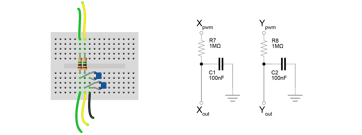
Connect one of the RC filters to output pin 5 of Arduino Pro Mini (that will transmit X coordinate) and the other to pin 6 (that will transmit Y coordinate).
Annotated sketch for Control module is supplied with the library and can be found at "examples/Example-03_Multiplexed/Example-03-1_Mux/Example-03-1_Mux.ino".
Main module in this example is comprised of single Arduino UNO that receives multiplexed signal of the buttons pressed from the Control module and decodes it using KeyDetector library. It also receives two axis signals from the analog stick of the controller.
Annotated sketch for Main module is supplied with the library and can be found at "examples/Example-03_Multiplexed/Example-03-2_Demux/Example-03-2_Demux.ino".
Connect output of the 3-bit DAC to pin A2 of the Arduino UNO; connect output of the RC filters to pin A1 (for X coordinate) and pin A0 (for Y coordinate). That is the only signal lines we use to transmit data from Control module to Main module. And if we opted not to transmit analog stick coordinates, we would left with only one signal line, holding state of 6 pressed buttons.
By increasing the resolution of the DAC we can easily ramp up the amount of maximum signal levels encoded into single analog line. The reasonable maximum bandwidth of R-2R ladder built using discrete components (resistors with 1% accuracy) equals to 5-bit, which is enough to encode up to 32 different signal levels, that should suffice for most of the gamepads out there. With bit counts beyond this the cost of ever increasing precision resistors may become restraining factor.
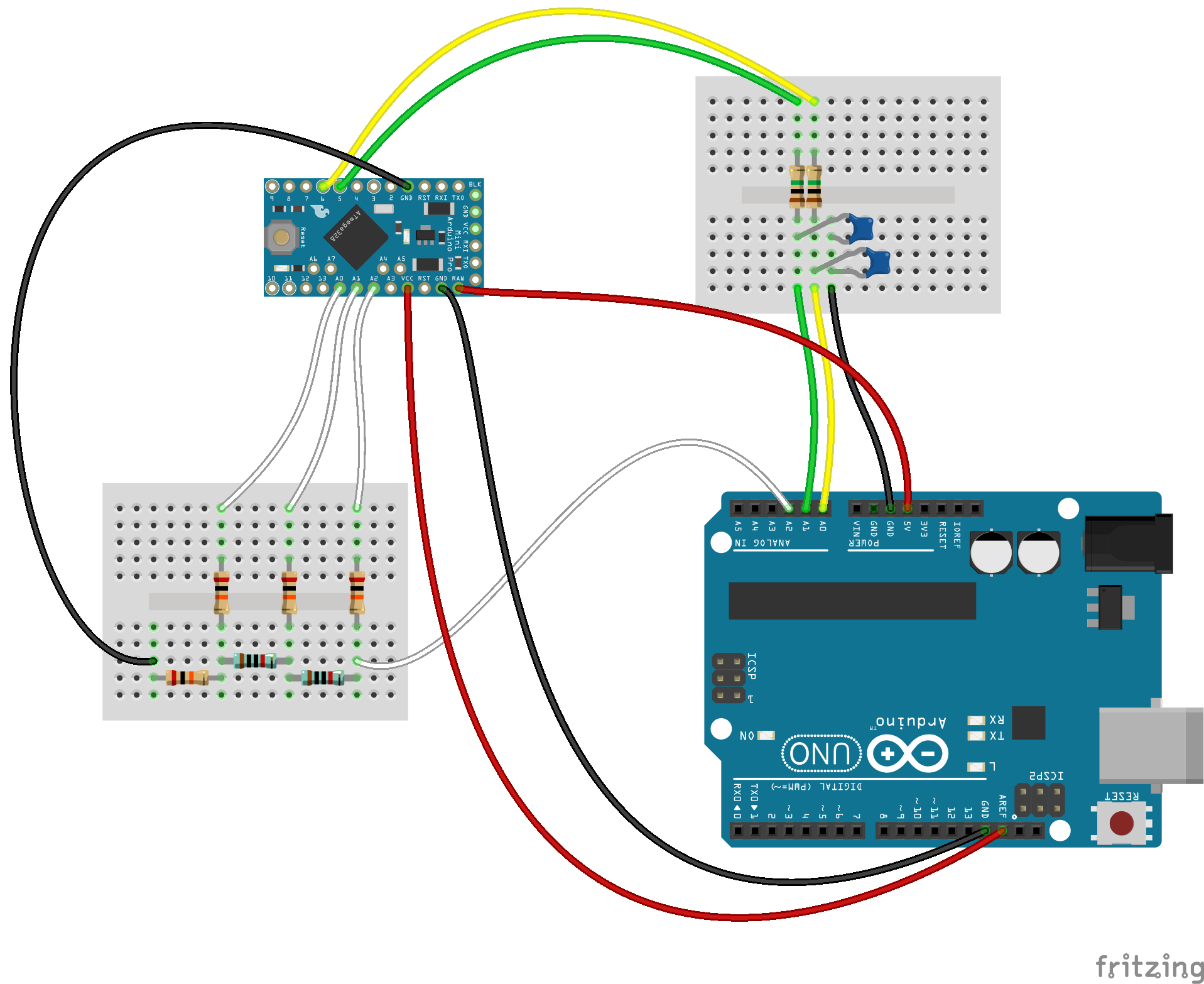
Connect GND and power lines as follows. Voltage for Control module is supplied through the 5V pin of Arduino UNO connected to RAW pin of Arduino Pro Mini. Also note the line that goes from VCC pin of Arduino Pro Mini to AREF pin of Arduino UNO. It is used to configure the reference voltage used for analog input (i.e. the value used as the top of the input range): analogReference(EXTERNAL).
Note that USB Host Shield with Bluetooth dongle is not shown on the following breadboard (it should, of course, be attached to Arduino Pro Mini).
Compile and upload Example-03-1_Mux.ino sketch to Arduino Pro Mini, and Example-03-2_Demux.ino to Arduino UNO. Leave Arduino UNO (a.k.a. “Main module”) connected to USB of your developer machine, open Serial Monitor and power up PS3 controller. Make sure it successfully connects to Arduino Pro Mini with USB Host Shield (a.k.a. “Control module”). Start pressing the buttons on the PS3 controller and moving the joystick. Name of the button (UP, RIGHT, DOWN, LEFT, O, X) being currently pressed will be printed. Position of the joystick, as it being moved, will be printed as well.

Low-pass filter and DAC both can be made into single shield that can be stacked on top of the Arduino Pro Mini. Here is an example of such shield.

It features three Low-pass filters similar to ones described above (with addition of the third filter connected to PWM pin 3) and 3-bit DAC, different from the described one in that it is connected to the output pins (A1, A2, A3) instead of (A2, A1, A0) with A3 being the least significant bit, LSB, and A1 - the most significant bit, MSB (hence the example sketch should be modified accordingly).
Fritzing PCB project files:
Note the orientation of the pins and choose export with/without mirroring accordingly, depending on the manufacturing process of your choice.