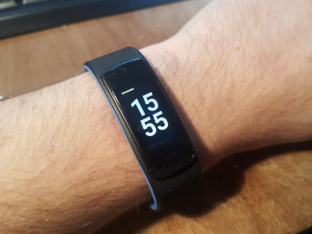
Custom firmware for the NRF52 based smartwatch I6HRC using the ARM Mbed RTOS. Supported by a custom version of the Gadgetbridge Android app.
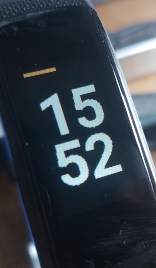
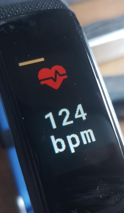
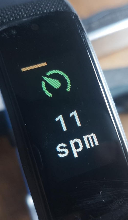
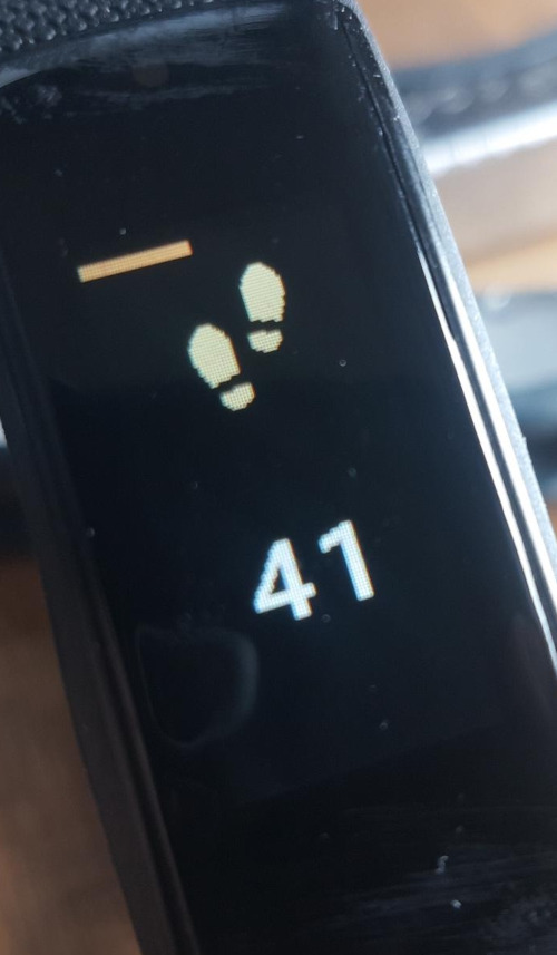
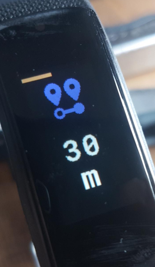
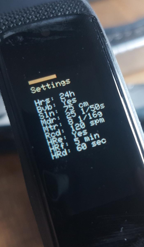
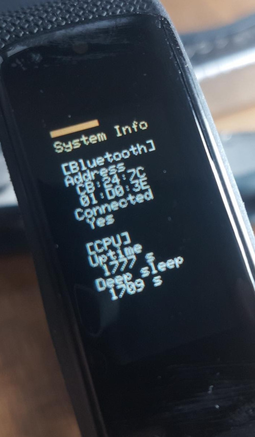
Photos
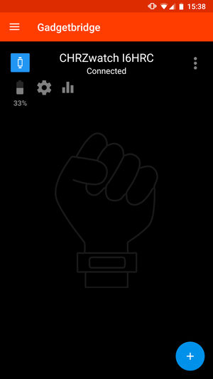
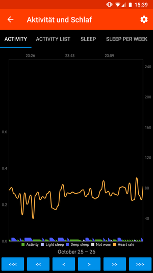
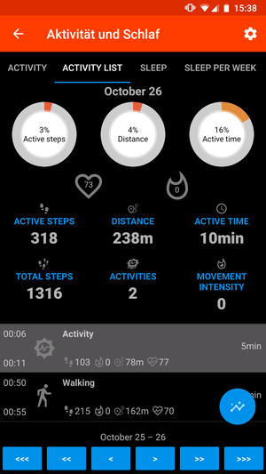
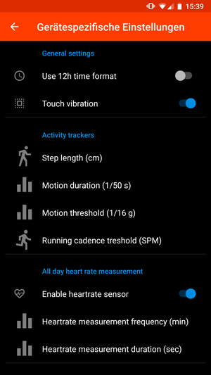
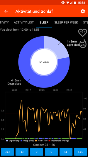
Android Screenshots
Bluetooth
- Complete BLE Stack
- Battery GATT profile
- Heartrate GATT profile
- Current time GATT profile
- Steps & cadence GATT profile
- Immediate alert GATT profile
- Text message GATT profile
- Health activity / sleep monitor GATT profile
- User configuration GATT profile
-
Proper bonding support
Hardware interfacing
- LC Display
- Vibration
- Charging detection
- Capacitive touch buttons
- Battery voltage sensor
- Acceleration sensor
- Heartrate sensor
Power saving
- Deep sleep in idle thread
- Energy saving display
- Energy saving touch input
- Energy saving heartrate sensor
- Energy saving acceleration sensor
- Endurance tests & verification
- Power saving BLE stack
- Use even better BLE stack (Requires ARMmbed/mbed-os#10669)
Other
- Timekeeping
- Graceful reboot on error
- Step detection algorithm
- Wake-up on wrist turn
- Heartrate detection algorithm
- User configurable settings
- High-speed LCD drawing
- Sleep / rest detection algorithm
-
Basic UI - Fancy UI
- Optional SEGGER J-Link RTT serial interface
-
Expose flash for external interfacing
Android app
Source code: https://codeberg.org/StarGate01/Gadgetbridge/src/branch/chrzwatch
- Basic device support
- Time synchronization
- Sample database
- Heartrate logging
- Step logging
- Sleep state logging
- Immediate alert on messages
- User settings editor
The I6HRC smartwatch uses these components. You can also purchase then separately (on breakout boards) and connect them to a NRF52-DK.
CPU: NRF52832 with 512K ROM, 64K RAM, supports deep sleep
- General: https://www.nordicsemi.com/Products/Low-power-short-range-wireless/nRF52832/Getting-started
- Datasheet: https://infocenter.nordicsemi.com/pdf/nRF52832_PS_v1.0.pdf
- RTOS: https://os.mbed.com/ (V6.7, development version, custom fork at https://github.com/StarGate01/mbed-os, branch
feature-nrf52-low-power-blemade compatible with PlatformIO )
Display: 0.96 inch, 80x160 pixel LCD with ST7735 driver IC
- Datasheet: https://www.displayfuture.com/Display/datasheet/controller/ST7735.pdf
- Driver: https://platformio.org/lib/show/7412/Adafruit_ST7735_Mini via Mbed SPI
Acceleration sensor: KX023
- General: https://www.kionix.com/product/KX023-1025
- Datasheet: http://kionixfs.kionix.com/en/datasheet/KX023-1025%20Specifications%20Rev%2012.0.pdf
- Application note: https://www.yic-electronics.de/datasheet/dc/ATS-19D-122-C2-R0.pdf
- Driver: https://platformio.org/lib/show/11101/kionix-kx123-driver via Mbed I2C and Mbed GPIO Interrupt
Heart rate sensor: AFE4404
- General: https://www.ti.com/product/AFE4404
- Datasheet: https://www.ti.com/lit/ds/symlink/afe4404.pdf
- Driver: https://platformio.org/lib/show/11099/Heartrate3_AFE4404 via Mbed I2C and Mbed GPIO
Font Flash: GT24L24A2Y, 2MB storage, top 4KB user writeable
- General: https://lcsc.com/product-detail/_Gotop-GT24L24A2Y_C124690.html
- Datasheet: https://datasheet.lcsc.com/szlcsc/1912111436_Gotop-GT24L24A2Y_C124690.pdf
- Map: https://github.com/RichardBsolut/GT24L24A2Y
- Driver: TBA via Mbed SPI and Mbed GPIO (Currently unused)
Ambient light sensor: Some photodiode combined with a LED
- Driver: N/A, currently unused
Battery voltage sensor: Down-scaled battery voltage (ca. 0.34V - 0.4V)
- Driver: Mbed ADC
Vibration motor: Small axial vibration motor
- Driver: Mbed GPIO
Buttons: Two capacitive buttons below display
- Driver: Mbed GPIO Interrupts
Charging detection: Down-scaled charging voltage (0V | 5V)
- Driver: Mbed GPIO
This project configures the NRF52832 IC and the Mbed OS as follows.
SPI and I2C interfaces
The NRF52832 IC has 2 I2C and 3 SPI instances, which partly overlap. To avoid contention, the interfaces are assigned as follows:
| Peripheral / Instance | Pin Mapping | Instance 0 | Instance 1 | Instance 2 |
|---|---|---|---|---|
| LC Display | 15, NC, 14 |
SPI2 |
||
| Acceleration Sensor | 3, 2 |
TWI0 |
||
| Heartrate Sensor | 20, 21 |
TWI1 |
||
| Font Flash | 8, 5, 7 |
SPI2 |
The reason for this particular configuration is a follows: Both the acceleration and heartrate sensor need to be able to access the I2C bus upon receiving an interrupt signal (to read a motion event upon occurrence and to read the ADC when it signals readiness, respectively). This means UnsafeI2C, - an I2C implementation without bus access locking - has to be used, because the mutex used for locking cant be used in an interrupt context.
Because these I2C access events may occur at any moment, a dedicated instance is allocated to each of them. The remaining instance does only support SPI anyways. To ensure no contention occurs between the LCD and the flash, the standard bus locking SPI functions are used. Due to this locking, parallel access to the LCD and font flash is impossible, but also not needed by the app logic. Locking also means that all functions using these devices cant be called from an interrupt context. Specifically, this concerns the Screen::render function. This function is intended to never be called directly, instead DisplayService::render has to be called, which defers the rendering call via the main EventQueue to the main thread.
At the time of writing, the font flash is unused. The interface mapping still stands, for future-proofing.
GPIO pins and interrupt memory
The NRF52832 IC has a few special functions which can be assigned to specific pins, eg. NFC and Reset. To use these pins as standard GPIO pins, the following macros are configured in mbed_app.json, in order to configure how Mbed is built: CONFIG_GPIO_AS_PINRESET is removed (enables p0.21 as GPIO) and CONFIG_NFCT_PINS_AS_GPIOS is added (enables p0.9 and p0.10 as GPIO). Also, the ITM debug trace module, which uses the SWO pin, is removed (enables p0.18 as GPIO). The ITM module is already removed in the board configuration this project inherits from (NRF52_DK).
To support more than one interrupt event on the GPIO pins (using the GPIOTE peripheral), more memory is allocated to the peripheral by defining NRFX_GPIOTE_CONFIG_NUM_OF_LOW_POWER_EVENTS=8. This supports a maximum of 8 separate interrupt events.
To conserve space, the ITM, SERIAL, SERIAL_ASYNC and SERIAL_FC devices are removed, as the serial connection is unavailable anyway (for more info, see below).
Mbed configuration
No proprietary softdevice by Nordic is used. Instead, Mbed supplies APIs like Bluetooth CORDIO (https://os.mbed.com/docs/mbed-cordio/19.02/introduction/index.html). This enables the usage of all software interrupts, by removing the SWI_DISABLE0 macro in mbed_app.json.
The Bluetooth API is modified in the custom Mbed OS fork, to enable deep sleep and reduce power usage. This modification might lead to some problems, but none have occurred so far.
Mbed also provides various RTOS features, e.g. Threads. (Enabled by defining PIO_FRAMEWORK_MBED_RTOS_PRESENT in platformio.ini)
Tho conserve energy, low-power timers are used. These are enabled by setting "events.use-lowpower-timer-ticker": true in mbed_app.json. The clock source for the low power clock is defined to be the external crystal oscillator by setting "target.lf_clock_src": "NRF_LF_SRC_XTAL".
Crash behavior
The system is configured to automatically reboot when a hard fault occurs ("platform.fatal-error-auto-reboot-enabled": true,). Although the number of these subsequent reboots is configured to be 3 ("platform.error-reboot-max": 3), this counter is set to 0 on each boot (mbed_reset_reboot_count()). This leads to an unlimited amount of reboots.
The crash dump retention feature of Mbed is enabled, and on the next boot after a crash the stored error information is printed out (in mbed_error_reboot_callback). The storage of this crash information requires a seperate memory region (.crash_data_ram), which is configured in the custom linker script patch/mbed/linker.ld.
If you have a RTT reader attached and compiled with RTT support, you can receive the message printed at reboot.
It is recommended to use Linux, however Windows should work as well, provided all the command line tools, compilers and interface drivers are installed.
-
(Required) Install Visual Studio Code (https://code.visualstudio.com/) and the PlatformIO (https://platformio.org/) extension. Then use the
i6hrc/i6hrc_debugenv for deployment, or eg. thenrf52_dk_debugenv for debugging on a NRF52-DK board.Important: Since this project uses a fork of Mbed that is not yet supported by PlatformIO, you have to initialize the builder environment by opening up a "
PlatformIO Core CLI" in VSCode and running$ pio system infoto print some information about your platformIO installation. Copy the python executable path and then install the required python packages:
$ <python path> -m pip install -r patch/requirements.txt -
(Optional) Install OpenOCD (http://http://openocd.org/), this is probably available via your package manager
-
(Optional) Install the nRF command line tools (https://www.nordicsemi.com/Products/Development-tools/nrf-command-line-tools) for J-Link support
-
(Optional) Install Doxygen (https://www.doxygen.nl/index.html, also via package manager) and use the "Build Documentation" task to generate documentation.
-
(Optional) Install or compile Fontedit (https://github.com/ayoy/fontedit) to edit the bitmap fonts (MSB first).
-
(Optional) Install GIMP (https://www.gimp.org/) to export the icons as XBM code files.
-
(Optional) Install the SEGGER J-Link tools (https://www.segger.com/downloads/jlink/) to connect to the RTT interface or to use a J-Link adapter.
Disassemble the watch and solder the SWCLK and SWDIO testpoints to the unused inner two USB data lines like shown in this video: https://www.youtube.com/watch?v=0Fu-VSuKHEg . Verify that the PCB actually contains a NRF52832 IC, and not an off-brand HS6620D IC.
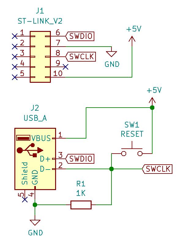
You might want to fabricate a custom SWD via USB to ISP adapter, link shown in the schematic below (KiCAD schematic is available in doc/schematics/swd-usb-adapter). You can still charge the watch using any USB A compliant charger or port.
The watch does not use read-back-protection. If it ever does, you might be able to use dirty hacks like https://github.com/StarGate01/nRF51822-siphon (untested, also probably incompatible).
Using a J-Link
To dump the stock ROM and RAM, use any J-Link adapter and the official Nordic dev tools (nrfjprog). Then, disassemble the watch to expose the internal testpoints. Connect the VDD, SWDIO and SWCLK testpoints and also the ground terminal. Then, dump the data like this:
$ nrfjprog -f nrf52 --readcode i6hrc_code.bin
You can also dump the contents of the RAM:
$ nrfjprog -f nrf52 --readram i6hrc_ram.bin
Using a CMSIS-DAP
For more info on the CMSIS-DAP, see below.
OpenOCD is able to to read the flash data as well, e.g. using a CMSIS-DAP adapter:
$ openocd -f interface/cmsis-dap.cfg -c "transport select swd" -f target/nrf52.cfg -c "init; reset halt; flash read_bank 0 i6hrc_code.bin; reset; exit"
Using other adapters should work as well, but is untested.
The original firmware dumps can also be found at doc/dump (armv7le) for decompiling (e.g. using Ghidra: https://ghidra-sre.org/) or restoring the watch (untested).
The flash memory has to be reset in oder for the chip to accept new firmware and debug instructions. This requires lower level SWD access (SWD), and thus cant be performed by the cheap ST-Link V2 clones because these only provide high level access (SWD_HLA).
Using a J-Link
Buy a J-Link adapter and connect it like in the paragraph above. This is annoying, since the internal VDD testpoint has to be tapped, requiring the watch to be disassembled. Hence, one of the other methods is recommended.
$ nrfjprog -f nrf52 --eraseall
Using a CMSIS-DAP
Either buy any CMSIS-DAP capable adapter, or buy a cheap ST-Link V2 clone (the little USB adapter one), and open it. Then use any SWD high level capable programmer, like for example another ST-Link V2 to reprogram the first one with the firmware for CMSIS-DAP functionality (https://raw.githubusercontent.com/x893/CMSIS-DAP/master/Firmware/STM32/hex/CMSIS-DAP-STLINK21.hex). You can use any ST-compatible flash tool, like for example the ST-Link utility or OpenOCD.
Then, connect the watch to the CMSIS-DAP, and the adapter to your PC via USB. Then connect to it using OpenOCD.
$ openocd -f interface/cmsis-dap.cfg -c "transport select swd" -f target/nrf52.cfg -c "init; reset halt; nrf5 mass_erase; reset; exit"
Using a Black Magic Probe
Buy or assemble - Bluepill boards (https://stm32-base.org/boards/STM32F103C8T6-Blue-Pill.html) are available for a few bucks - a Black Magic Probe (https://github.com/blacksphere/blackmagic/wiki). Connect the SWD interface to the watch, and the probe via USB to your PC. Then connect to the probe using GDB.
$ arm-none-eabi-gdb
(gdb) target extended-remote /dev/ttyACM0
(gdb) set non-stop on
(gdb) mon swdp_scan
(gdb) mon erase_mass
Flashing the unlocked chip should then work with any basic SWD capable programmer, like the ST-Link V2 (the cheap clones work too). The CMSIS-DAP or the Black Magic Probe can be used as well.
You can use OpenOCD to connect to the chip and manage its flash memory ("..." denote subsequent commands or arguments):
High level SWD access using a ST-Link V2 clone
$ openocd -f interface/stlink-v2.cfg -c "transport select hla_swd" -f target/nrf52.cfg -c "init; reset halt; ...; reset; exit"
Lower level SWD access using a CMSIS-DAP (recommended)
$ openocd -f interface/cmsis-dap.cfg -c "transport select swd" -f target/nrf52.cfg -c "init; reset halt; ...; reset; exit"
Lower level SWD access using a J-Link (not recommended)
$ nrfjprog -f nrf52 ...
The J-Link tools are able to communicate with the CMIS-DAP interface as well.
The PlatformIO IDE is set up to use OpenOCD via some hardware adapter (default: CMSIS-DAP) to program the chip. This can be changed in the platformio.ini file. For the watch, use the i6hrc configuration.
The PlatformIO IDE is able to use either a CMSIS-DAP or J-Link adapter for interactive debugging. The i6hrc_debug and nrf52_dk_debug configurations provide debugging support. Do note that the watchdog timer might kill your debugging session. The host may use the J-Link debugger software (which is able to connect to a CMSIS-DAP as well) or the CMSIS_DAP debugger software by PlatformIO (default).
Since the RX, TX and SWO pins are used for other peripherals, UART and SWO communication is not possible. The firmware thus implements a SEGGER J-Link RTT interface (https://www.segger.com/products/debug-probes/j-link/technology/about-real-time-transfer/), which communicates via the SWD debug interface. To access this interface, either the SEGGER RTT tools or J-Link tools are required. Use JLinkRTTViewer or the other tools to open a socket, then connect to it via a terminal at socket://localhost:19021 (default port).
$ JLinkExe -autoconnect 1 -device NRF52832_XXAA -if SWD -speed 4000 -RTTTelnetPort 19021 &
$ telnet localhost 19021
Add the compiler definition SEGGER_RTT to enable this feature. The task "Start Monitor Server" automates the connection.
Unfortunately, the SWD RESET line is not easily accessible. However, shorting SWDCLK to VCC triggers a debug init halt as well.
If the watch refuses to flash, hangs in low power mode or is stuck in a bootloop, try connecting to it using OpenOCD while spamming the reset button on your adapter - hoping the debugger attaches before the error state occures. This should not be needed during normal flashing and execution. Sometimes, this reset condition occurs randomly when the SWDCLK pin is left floating due to EMI and long wires. This is also the reason for the pulldown resistor in the schematic above.
On a successful connection OpenOCD displays something like "Info : nrf52.cpu: hardware has 6 breakpoints, 4 watchpoints". This means the chip was reset, caught and is now in debug mode.
The script tools/reset.sh or the task "Reset Target" automates this spamming, waiting for you to press the reset button.
Optionally, append -c "reset halt" to the OpenOCD command. The chip then halts at the first instruction, which may be good for debugging.
The font rom is internally connected to the main CPU via SPI and implements a fairly standard flash command interface.
Unfortunately, neither the NRF52832 nor the flash used support or use the QSPI interface, which would allow mapping the flash address range and accessing it via the MMU. This would enable remote reading and writing of the flash via the SWD connection.
It is possible to write a RamCode (https://wiki.segger.com/Programming_External_SPI_Flashes) using the SEGGER Open Flashloader framework (https://wiki.segger.com/Open_Flashloader). Then, a tool like J-Flash would be able to access the external flash via the RamCode on the CPU. This is however quite trick to do. Instead, the OpenOCD "on chip flash loader" protocol by Pavel Chromy (http://openocd.org/doc/html/Flash-Commands.html) could be implemented.
Some python scripts are used to communicate with the chip using the RTT interface. However, a proper SPI flash driver is still missing and has yet to be fully implemented (#1).
A fork of the Android app Gadgetbridge (https://gadgetbridge.org/) with support for this firmware is available at Codeberg: https://codeberg.org/StarGate01/Gadgetbridge/src/branch/chrzwatch .
You can use the Android app "nRF Connect" (https://play.google.com/store/apps/details?id=no.nordicsemi.android.mcp) to test the Bluetooth functions. Sometimes, connecting takes multiple tries.
Various other apps like e.g. FitoTrack (https://play.google.com/store/apps/details?id=de.tadris.fitness) are able to read the heartrate from this sensor. Update: The device has not to be bonded in the recent version.
Thanks to Aaron Christophel for providing instructions on how to modify the hardware, mapping out the pins and providing some demo Arduino code.
- https://github.com/atc1441
- https://atcnetz.blogspot.com/2019/02/arduino-auf-dem-fitness-tracker-dank.html
- https://www.mikrocontroller.net/topic/467136
- https://www.youtube.com/watch?v=0Fu-VSuKHEg
Please note that while most code in this repository is licensed under the terms of the GPLv3 license, this explicitly does not apply to the libraries contained in /lib, fonts in /res/fonts, images in /res/img, patches in /patch and the file /doc/pinout.png. All these documents have their own license attached.
Fonts can be found in /res/fonts.
Standard ascii 5x7
- Author: Adafruit
- URL: https://platformio.org/lib/show/12501/Adafruit_GFX
- License: Apache 2.0
Roboto Mono Bold [24pt, 36pt, 48pt]
- Author: Google
- URL: https://fonts.google.com/specimen/Roboto
- Selected subset of glyphs
- License: Apache 2.0
Images can be found in /res/img.
MDI heart-pulse [36px]
- Author: Google
- URL: https://materialdesignicons.com/
- License: Apache 2.0
MDI map-marker-distance [36px]
- Author: Michael Richins
- URL: https://materialdesignicons.com/
- License: Apache 2.0
MDI shoe-print [36px]
- Author: Michael Irigoyen
- URL: https://materialdesignicons.com/
- License: Apache 2.0
MDI speedometer [36px]
- Author: Austin Andrews
- URL: https://materialdesignicons.com/
- License: Apache 2.0
Patches to Mbed can be found in /patch.
ARM Mbed RTOS and API
- Original author: ARM Mbed Team
- URL: https://os.mbed.com/, Fork: https://github.com/StarGate01/mbed-os
- Use branch
feature-nrf52-low-power-ble - Add PlatformIO metadata
- Replace NRF52 linker memory map to support crash dump retention
- License: Custom - see https://github.com/ARMmbed/mbed-os/blob/master/LICENSE.md
All modified libraries have been or will be published to https://platformio.org , their source code can be found in /lib.
CurrentTimeService
- Original author: Takehisa Oneta
- URL: https://os.mbed.com/users/ohneta/code/BLE_CurrentTimeService/
- Modifications:
- URL: https://platformio.org/lib/show/7372/BLE_GATT_Services
- Deferred calls in ISR context to EventQueue
- Added documentation
- Added LOW_POWER macro (default 1) to use a low-power ticker.
- Exposed monotonic timer callback
- License: GPLv3
Adafruit_GFX
- Original author: Adafruit
- URL: https://github.com/adafruit/Adafruit-GFX-Library
- Modifications:
- Original author: Andrew Lindsay
- URL: https://platformio.org/lib/show/2147/Adafruit_GFX
- Modifications:
- URL: https://platformio.org/lib/show/12501/Adafruit_GFX
- Added buffered high-speed drawing functions
- Move font to .text
- License: Apache 2.0
Adafruit_ST7735_Mini
- Original author: Adafruit
- URL: https://github.com/adafruit/Adafruit-ST7735-Library
- Modifications:
- Original author: Andrew Lindsay
- URL: https://platformio.org/lib/show/2150/Adafruit_ST7735
- Modifications:
- URL: https://platformio.org/lib/show/7412/Adafruit_ST7735_Mini
- Added support for the
R_MINI160x80display type - Added documentation
- Added an explicit dependency to
Adafruit_GFXport, see above - Added SPI speed configuration
- Added high-speed buffered drawing functions
- License: Apache 2.0
UnsafeI2C
- URL: https://platformio.org/lib/show/12500/UnsafeI2C
- License: Apache 2.0
GT24L24A2Y
- URL: (Unpublished, unfinished)
- License: GPLv3
Heartrate3_AFE4404
- Original author: MikroElektronika / Corey Lakey:
- URL: https://github.com/MikroElektronika/Click_Heartrate3_AFE4404
- Modifications:
- URL: https://platformio.org/lib/show/11099/Heartrate3_AFE4404
- Added Mbed integration
- Added interrupt handling
- Added power down/up functionality
- Added an explicit dependency to
UnsafeI2C, see above
- License: GPLv2
kionix-kx123-driver
- Original author: Rohm
- URL: https://platformio.org/lib/show/3975/kionix-kx123-driver
- Modifications:
- URL: https://platformio.org/lib/show/11101/kionix-kx123-driver
- Adapted to Mbed
- Added interrupt configuration functionality
- Added motion detecting functionality
- Fixed include paths
- Add tilt detecting feature
- License: Apache 2.0
RegisterWriter
- Original author: Rohm / Mikko Koivunen
- URL: https://platformio.org/lib/show/10695/RegisterWriter
- Modifications:
- URL: https://platformio.org/lib/show/11100/RegisterWriter
- Adapted to Mbed
- Fixed include paths
- Fixed default pins
- Added an explicit dependency to
UnsafeI2C, see above
- License: Apache 2.0
JLink_RTT
- Original author: SEGGER
- URL: https://www.segger.com/products/debug-probes/j-link/technology/about-real-time-transfer/ (JLink_V630D/Samples/RTT/SEGGER_RTT_V630d.zip)
- Modifications:
- Original author: James Wang
- URL: https://github.com/woodsking2/sabomo_jlink_rtt
- Modifications:
- URL: https://platformio.org/lib/show/12534/JLink_RTT
- Removed redundant printf implementation, use the one of Mbed
- Use Mutex instead of Thread_safe
- Add serial input
- Add example
- License: GPLv3 / Custom - see files
File /doc/pinout.png
- Original author: Aaron Christophel
- URL: https://atcnetz.blogspot.com/2019/02/arduino-auf-dem-fitness-tracker-dank.html
- License: All rights reserved, fair use