Implementing support for high-order finite-element functions in XDMF3 for ParaView using VTK lagrange cells
First of all, any help is appreciated!
- Initial implementation
- First tests
- Tests with multiple attributes and vector sizes
- Large-scale tests with HDF5
- Feedback from the community
- Release candidate after bugfixing
- Merge into VTK mainline
- Use in ParaView mainline
- Update XDMF3 documentation
- Add more cell types and/or methods
As of June 2020, the XDMF3 data format supports finite-element functions on various cell types with functions up to degree 2 [1]. This is not a limitation of the XDMF3 standard, but of the XDMF3 to VTK [6] converter, which e.g. ParaView [2] uses.
Until Summer 2018, VTK only supported higher-order cells on a case-by-case basis. The newly introduces lagrange cell types [5] provide higher-order cell types in a unified manner and also for orders greater than 2. Support in XDMF3 has been requested by the community [4].
The existing implementation by Michal Habera [3] [7] provides a great starting point to implement the new cell converter.
The XML layout of the new FiniteElementFunctionLagrange ItemType is very similar to the existing FiniteElementFunction ItemType.
Notable new additions are:
- Orders above 2 (up to 10 by default) are supported.
- Both the DOF values and the barycentric positions of the DOFs may be specified.
- Both data segments may be either - and independently from each other - explicitly indexed, or assumed to be continuous.
- Data may be specified to be interpreted as VTK ordered, or row ordered.
- DOF positions may be specified once for all cells int the attribute.
- Multiple attributes on one cell are supported
- Remove zero-padding on vectors, thus enabling 2D vectors and preventing inconsistencies in spatial collections.
Notable new limitations are:
- Only triangle cells are implemented for now, but more cell types (eg. tetrahedra) could be added without much effort.
- Only the DG and CG methods are implemented for now.
- Order 0 (cell-based data) is not supported. The minimum order is 1 (node-based data). This is a limitation of VTK lagrange cells.
Notable continued limitations are:
- Non-intuitive behavior when using multiple attributes in one cell. See the section below for details.
Just like before, specify a XDMF3 attribute, but use the FiniteElementFunctionLagrange item type.
<Attribute Name="Test" ItemType="FiniteElementFunctionLagrange"
    ElementFamily="XX_YY_ZZ" ElementDegree="4" ElementCell="triangle"
    Center="Other" AttributeType="Scalar">
ElementDegreemay be1to10(can be increased by recompiling VTK)AttributeTypemay beScalar,Vector,TensororTensor6ElementCellmay betriangle
The <Attribute> element may contain 1 to 4 sub-elements, the <DataItem> elements. Those contain the DOF values, positions and potential indices.
The ElementFamily attribute has been extended to contain information not only about the method, but also the data layout. The value must be in the form XX_YY_ZZ, with the segments being one of the following.
XX, the method parameter may be:
DG: Discontinuous GalerkinCG: Continuous Galerkin
YY, the DOF value layout parameter, may be:
CV("Continuous VTK", +1DataItem): The DOF values are assumed to be continuous in the firstDataItem, and be in VTK order [5].CR("Continuous Row", +1DataItem): The DOF values are assumed to be continuous in the firstDataItem, and be in row order.EV("Explicit VTK", +2DataItems): The firstDataItemis assumed to contain indices for the secondDataItem, which contains the DOF values. The values obtained are assumed to be in VTK order [5].ER("Explicit Row", +2DataItems): The firstDataItemis assumed to contain indices for the secondDataItem, which contains the DOF values. The values obtained are assumed to be in row order.
A vector may be given in a dimension lower or equal to 3.
ZZ, the DOF position layout parameter, may be:
CV,CR,EV,ER: The same as above, but in relation to theDataItems which come after theDataItems of the DOF values.D("Default", +0DataItems): NoDataItems have to be specified, and all DOFs will be spaced equidistantly over the cell automatically.
If the DOF position buffers are shorter than the DOF value buffers, they will loop around. This means that when the DOF positions are specified for only one cell, they will apply to all cells, conserving storage space.
Unlike the previous implementation, which used a custom point order, this one uses VTK or row ordering. Internally, as VTK requires VTK ordering, the row ordering is converted. The ordering works like this:
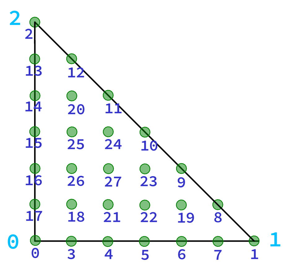
VTK Order: (Degree 6)
Row Order: (Degree 6)
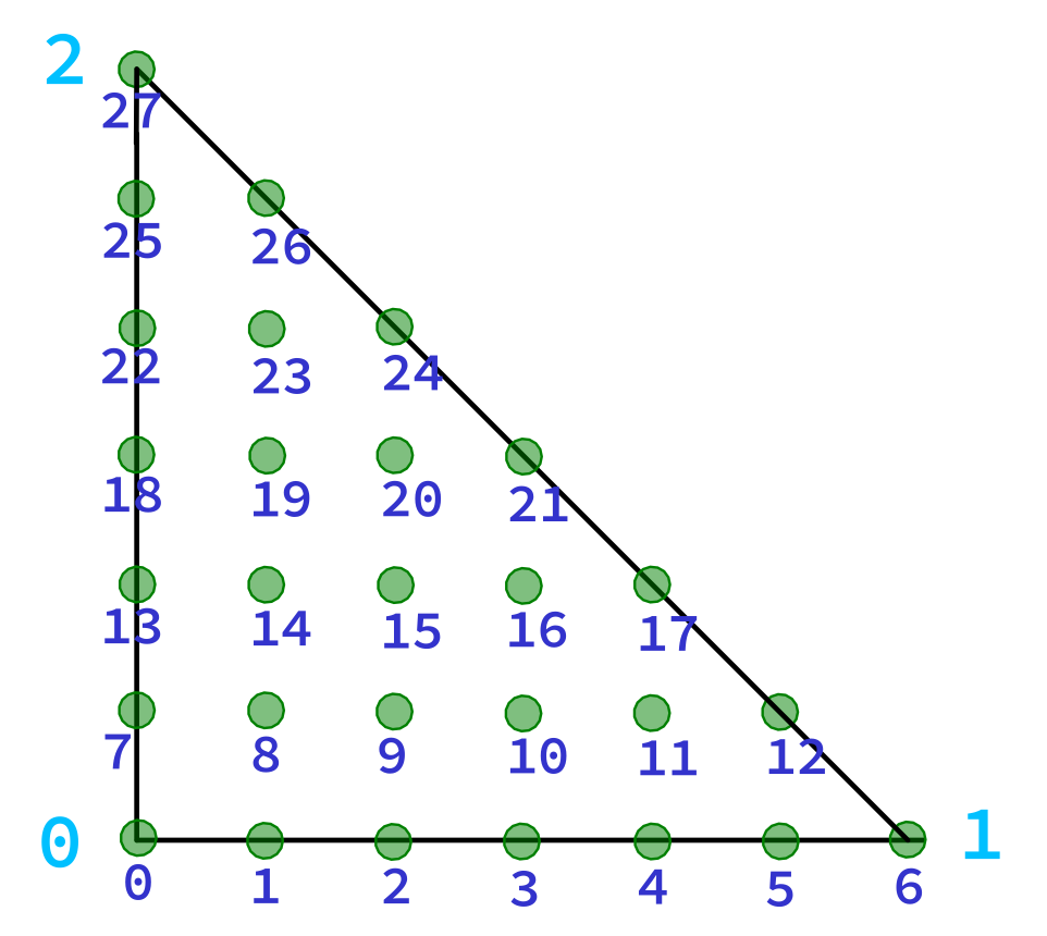
Light blue: Triangle vertex indices, dark blue: DOF indices. For more info on the VTK ordering, see https://blog.kitware.com/modeling-arbitrary-order-lagrange-finite-elements-in-the-visualization-toolkit/ .
The positions of the DOFs are specified in barycentric coordinates. See https://en.wikipedia.org/wiki/Barycentric_coordinate_system for more info. The nth coordinate relates to edge which is opposite of the nth vertex of the triangle.
The FiniteElementFunctionLagrange attributes actually modifies the geometry of the underlying cell. (So does the legacy FiniteElementFunction)
Thus, when using multiple FiniteElementFunctionLagrange attributes, the DOF position specification of the last one will "win". This means that any preceding node-based attributes (cell-based attributes remain untouched, as they are kept in a separate buffer) will be wrongly re-positioned/re-mapped to the new DOFs. Also, non-finite-element attributes (simple value arrays) will be re-mapped to the new DOFs as well, instead of to the vertices they were intended for. As you can see, it is advisable to use FiniteElementFunctionLagrange for either all or no node attributes of a cell.
Also, the degrees of the finite-element attributes may not be different from each other, as this would cause different amounts of DOFs in the cell, which would cause re-mapping as well.
If you need cells with different degrees or DOF locations, group them into sets and create a <Grid> in a <Grid GridType="Collection" CollectionType="Spatial"> collection for each set. If you need attributes with differing DOFs/degrees on the same cell, duplicate the cell in two different sets and use some filter in your visualization software to display the correct set.
In ParaView, you can use the "Nonlinear Subdivision Level" Slider in the advanced properties (click the little gear icon) to generate more geometry and smooth the cell.
Also keep an eye on the standard error output stream of the ParaView process, any errors detected by the lagrange converter will be written there.
This image builds ParaView with a fork of VTK (https://gitlab.kitware.com/ChristophHonal/vtk/-/tree/xdmf3-highorder), which aims to enable high-order finite-element functions in XDMF.
First, clone this repository and the VTK submodule. You need a git account at gitlab.kitware.com with an SSH key.
git clone --recursive git@github.com:StarGate01/paraview-dev.git
cd paraview-dev
Then, build the image:
UID=$UID GID=$GID docker-compose build paraview_release
Temporarily remove the host mounts (the volumes section) in docker-compose.yml for the paraview_debug container, then copy the pre-compiled objects from the image to your working directory:
UID=$UID GID=$GID docker-compose run --rm --entrypoint "bash -c 'rsync -avt /app/paraview-build/ /tmp'" -v $(pwd)/build:/tmp:rw paraview_debug
Re-add the volume mounts to the docker-compose.yml, make your changes in the VTK submodule, then recompile the modified sources:
UID=$UID GID=$GID docker-compose run --rm paraview_debug
Docker Compose mounts $(pwd)/build to /app/paraview-build and $(pwd)/VTK to /app/paraview-build/superbuild/paraview/src/VTK, this means that the VTK submodule shadows the original VTK source in build.
First, build the image:
UID=$UID GID=$GID docker-compose build paraview_release
Then, recompile the sources and create an AppImage:
UID=$UID GID=$GID docker-compose run --rm paraview_release
The compiled AppImage will be in $(pwd)/release, and include all dependencies like QT, HDF5 and Python.
A precompiled AppImage can be found here: https://syncandshare.lrz.de/getlink/fiJDmXw6f2aVLhsXUj3mbia4/paraview-5.8.0-xdmf3-highorder-release-x86_64.AppImage .
A docker image (e.g. for servers) can be found here: https://hub.docker.com/r/stargate01/pv-v5.8.0-osmesa-py3-xdmf3-highorder .
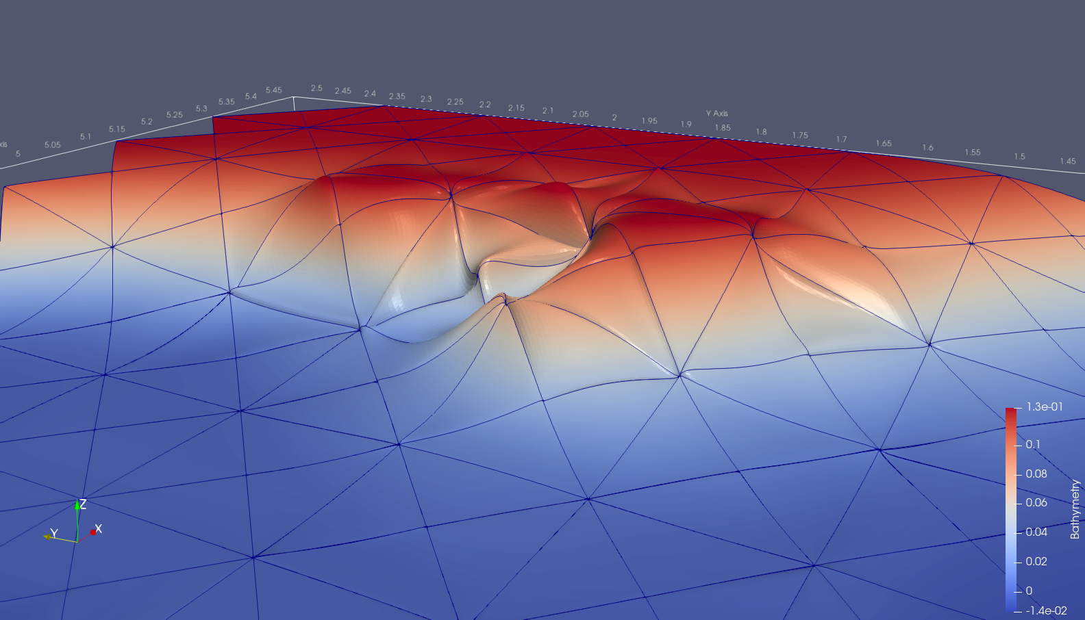
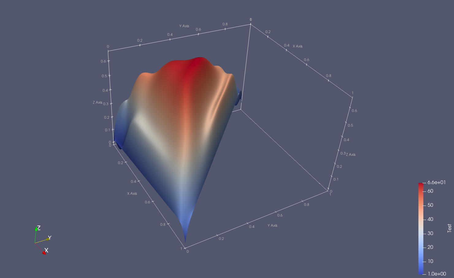
XMF files for demonstration can be found in the test directory of this repository. Some images can be found in the test/images directory.
- [1] http://www.xdmf.org/index.php/XDMF_Model_and_Format#Attribute
- [2] https://www.paraview.org/
- [3] https://github.com/michalhabera/gsoc-summary
- [4] https://gitlab.kitware.com/xdmf/xdmf/-/issues/18
- [5] https://blog.kitware.com/modeling-arbitrary-order-lagrange-finite-elements-in-the-visualization-toolkit/
- [6] https://vtk.org/
- [7] http://karlin.mff.cuni.cz/~habera/?p=gsoc17