Hardware and software for a power and IO extension PCB with current monitoring and I2C interface.
This project has been generously supported by PCBWay. Read more about this project and also my review of the manufacturing on my blog: Design And Assembly Of An I2C Relay PCB
Use KiCad with my CustomComponents library to view and edit the hardware project, or download the fabrication files for PCB and/or PCBA manufacturing. I used KiBOM to generate the BOM. You can also download the complete schematics as PDF.
See the Arduino library documentation for usage with the Arduino framework. The library is also available on PlatformIO. Use Visual Studio Code and the PlatformIO plugin to edit the Arduino library and tests.
See the Raspberry Pi library documentation for usage with the Raspberry Pi Python 3 smbus framework.
- Power input via
5Vand3V3pins- Min.
250mA @ 5Vto actuate all four relays simultaneously - Less than
30mA @ 5Vstandby current 3V3voltage level is only required for I2C level shifting if the I2C signal level is3.3Vinstead of5V
- Min.
- I2C bus for connection to a I2C master via JST header
RPI- I2C bus passthrough via JST header
PASS - Internal pullup resistors
- Level-shifting
3.3V - 5Vtolerant bus
- I2C bus passthrough via JST header
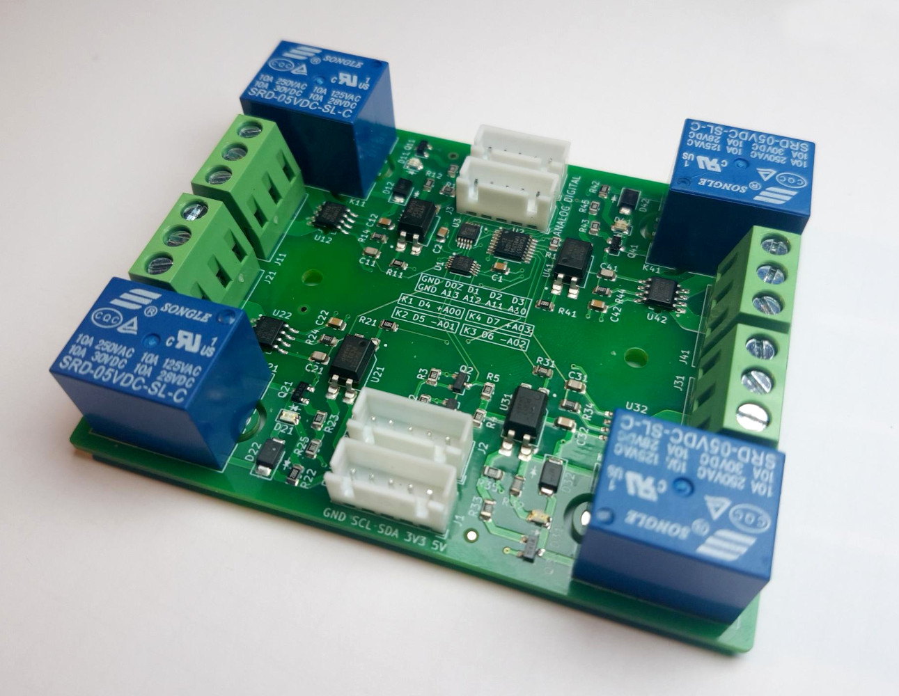
- Four
SRD-05VDC-SL-Cthree-lead (NC - COM - NO) magnetic relays- Each has a
CC6902SO-10Ainductive current measuring IC connected acrossCOM - Galvanically isolated driver circuit using an optocoupler
- Flyback diode protection
- Red status LED indicates
COM - NOactuation 2ozthick copper traces enable high currents- Isolation milling reduces risk of shorting in damp environments
- Maximum power:
10A, 250VAC, 110VDC - Contact load rating: resistive
7A @ 28VDC,10A @ 125VAC,7A @ 240VAC, inductive3A @ 120VAC,3A @ 28VDC
- Each has a
- One
PCA95578-channel GPIO port (I2C address:0x18), logic level0V | 5V- GPIO channels
0Z-3connected to JST headerDIGITAL - Relays are connected to GPIO channels
4-7 - Maximum current (except channel
0Z):25mAsink,20mAsource per channel, max. total:100mAsink,85mAsource - Channel
0Zis high-impedance and open-drain (see datasheet for details)
- GPIO channels
- Two
ADS11154-channel 16-bit ADC ports, voltage range0V - 5V- All four pins of ADC 1 connected to current measuring ICs (I2C address:
0x48) - All four pins of ADC 2 connected to JST header
ANALOG(I2C address:0x49) - Configurable sample rate and gain amplifier
- Max.
10mAcontinuous input current
- All four pins of ADC 1 connected to current measuring ICs (I2C address:
For further specifications and ratings, all datasheets can be found in this repository.
Due to the inherent nature of magnetic relays, the inductive current measuring ICs and also the ADCs experience a measurement offset while the relays are energized. It is recommended to measure the actual load at a distance from the board, in order to obtain reference values. These reference values should then be used to compute an offset or function for each channel and amount of relays energized.
For no load (floating) using an Arduino Uno, the maximum absolute measurement offset was found to be about as follows.
| Amount of relays energized | Offset at energized channel | Offset at disabled channel |
|---|---|---|
| 0 | 0.05A |
0.05A |
| 1 | 1A |
0.7A |
| 2 | 1.5A |
1.3A |
| 3 | 2A |
1.8A |
| 4 | 2.4A |
N / A |
Please note that these offsets are dependent on load and environmental factors.
17 unique parts, 60 SMT parts, 12 THT parts on a double-sided 90mm x 71mm PCB with 2oz copper finish.
Component cost per board: about $25 (Ignoring shipping, bulk discounts and changes in price over time).
BOM
| Item # | Designator | Quantity | Manufacturer | Manufacturer Part # | Description / Value | Distributor | Distributor part # | Package / Footprint | Type | Notes |
|---|---|---|---|---|---|---|---|---|---|---|
| 1 | C11, C21, C31, C41 | 4 | Any | TBD | CAP CER 100PF MAX. 5% MIN. 10V 0805 SMD | Any | TBD | SMD 0805 | SMD | |
| 2 | C1, C2, C12, C22, C32, C42 | 6 | Any | TBD | CAP CER 100NF MAX. 5% MIN. 10V 0805 SMD | Any | TBD | SMD 0805 | SMD | |
| 3 | D12, D22, D32, D42 | 4 | Shikues | 1N4007F | DIODE 1N4007 SMAF | LCSC | C110856 | SMAF | SMD | |
| 4 | D11, D21, D31, D41 | 4 | Everlight Elec | 17-21SURC/S530-A3/TR8 | LED RED 2V 0805 SMD | LCSC | C72037 | SMD 0805 | SMD | |
| 5 | J1, J2, J3, J4 | 4 | Any | TBD | CONN JST-XH PITCH-2.50MM VERTICAL MALE 5 PIN | Any | TBD | Through Hole | PTH | |
| 6 | J11, J21, J31, J41 | 4 | Ningbo Kangnex Elec | WJ128V-5.0-3P | CONN SCREW TERMINAL PITCH-5.0MM 3 PIN 20A | LCSC | C8270 | Through Hole | PTH | |
| 7 | K11, K21, K31, K41 | 4 | Ningbo Songle Relay | SRD-05VDC-SL-C | RELAY SEALED SENSITIVE 5V 10A | LCSC | C35449 | Through Hole | PTH | |
| 8 | Q1, Q2 | 2 | Shikues | BSS138 | MOSFET N-CH SOT-23-3 | LCSC | C112239 | SOT-23-3 | SMD | |
| 9 | Q11, Q21, Q31, Q41 | 4 | Nexperia | PMBT3904,215 | BJT NPN SOT-23-3 | LCSC | C8667 | SOT-23-3 | SMD | |
| 10 | R14, R24, R34, R44 | 4 | Any | TBD | RES 100 OHM MAX. 1% MIN. 1/8W 0805 SMD | Any | TBD | SMD 0805 | SMD | |
| 11 | R11, R12, R21, R22, R31, R32, R41, R42 | 8 | Any | TBD | RES 200 OHM MAX. 1% MIN. 1/8W 0805 SMD | Any | TBD | SMD 0805 | SMD | |
| 12 | R1, R13, R23, R33, R43 | 5 | Any | TBD | RES 1K OHM MAX. 1% MIN. 1/8W 0805 SMD | Any | TBD | SMD 0805 | SMD | |
| 13 | R2, R3, R4, R5, R15, R25, R35, R45 | 8 | Any | TBD | RES 10K OHM MAX. 1% MIN. 1/8W 0805 SMD | Any | TBD | SMD 0805 | SMD | |
| 14 | U1, U3 | 2 | Texas Instruments | ADS1115IDGSR | IC I2C 4 CH ADC VSSOP-10 | LCSC | C37593 | VSSOP-10 | SMD | |
| 15 | U12, U22, U32, U42 | 4 | Cross Chip | CC6902SO-10A | IC CURRENT SENSOR 5V 10A SOP-8 | LCSC | C350865 | SOP-8 | SMD | |
| 16 | U11, U21, U31, U41 | 4 | Sharp Microelectronics | PC817X2CSP9F | IC OPTOCOUPLER SMD-4 | LCSC | C66405 | SMD-4 | SMD | |
| 17 | U2 | 1 | NXP Semicon | PCA9557PW,118 | IC I2C 8 CH IO EXPANDER TSSOP-16 | LCSC | C141380 | TSSOP-16 | SMD |