This a note about building a coffee table book sized speaker based on the SB Acoustics SB16PFCR25-4-COAX, a 40W 6" Coaxial driver, inspired by (copied from) Ojas Artbook speakers. It is not a ready-to-build kit.
- I'd never made a speaker before, and wanted to try.
- I'm no kind of audiophile, and don't want to go too far down that rabbit hole.
- I was super inspired by the Ojas Artbook speaker kit, but they were out of stock, in the US and a little to big and expensive for me.
- I don't really have the space or the confidence to do any serious woodwork (cutting and routing) so wanted to try ordering CNC cut parts and glueing them together.
- I wanted something that would sound and look better than the Q Acoustics 3010 speakers I bought from Richer Sounds a few years ago. I wanted reasonably deep bass, decent volume from a little digital amp and a sound that wasn't boxy.
- These are not super precisely designed speakers. If you have the patience to model everything properly, I'm sure you can do better.
- This is NOT a ready-to-go kit you can just send to a CNC place and build easily. The design in the attached Illustrator file is not correct — I'll explain why below, and you can maybe modify it to work better.
- For the money you'll spend on parts, you can probably buy a better speaker. If you include your own time at minimum wage, you can buy a much better speaker.
- Wooden parts, cut from 18mm (nominal) Plywood. Use the best plywood you can get, in the UK in 2022 it's hard to get high grade (B/BB) Birch Ply, this was built from good quality (BB/BB) ply. This was expensive - over £300 with a few other parts, there may well be ways to optimise the process and certainly cheaper ways to cut the simple parts.
- Drivers: SB Acoustics SB16PFCR25-4-COAX 6" Coaxial Speaker × 2, ~£40 each from Willys Hifi
- Cable: I used 1mm three core mains cable, other cables exist.
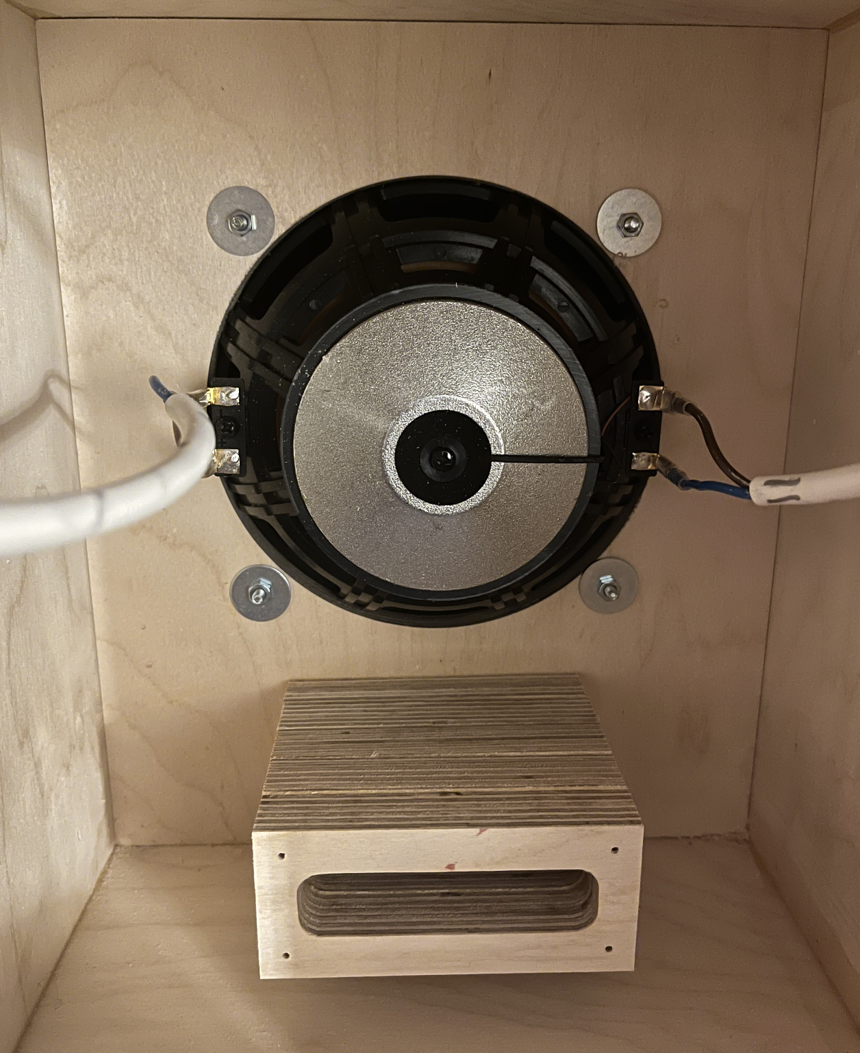
- M4 bolts, washers, nuts to attach the driver to the front of the box.
- M3 hex brass standoffs to mount the crossover into the...
- M3 Rivet Nuts which I hammered into the wood.
- Female Spade Terminals in 2.8mm and 4.8mm to connect wires to the speakers.
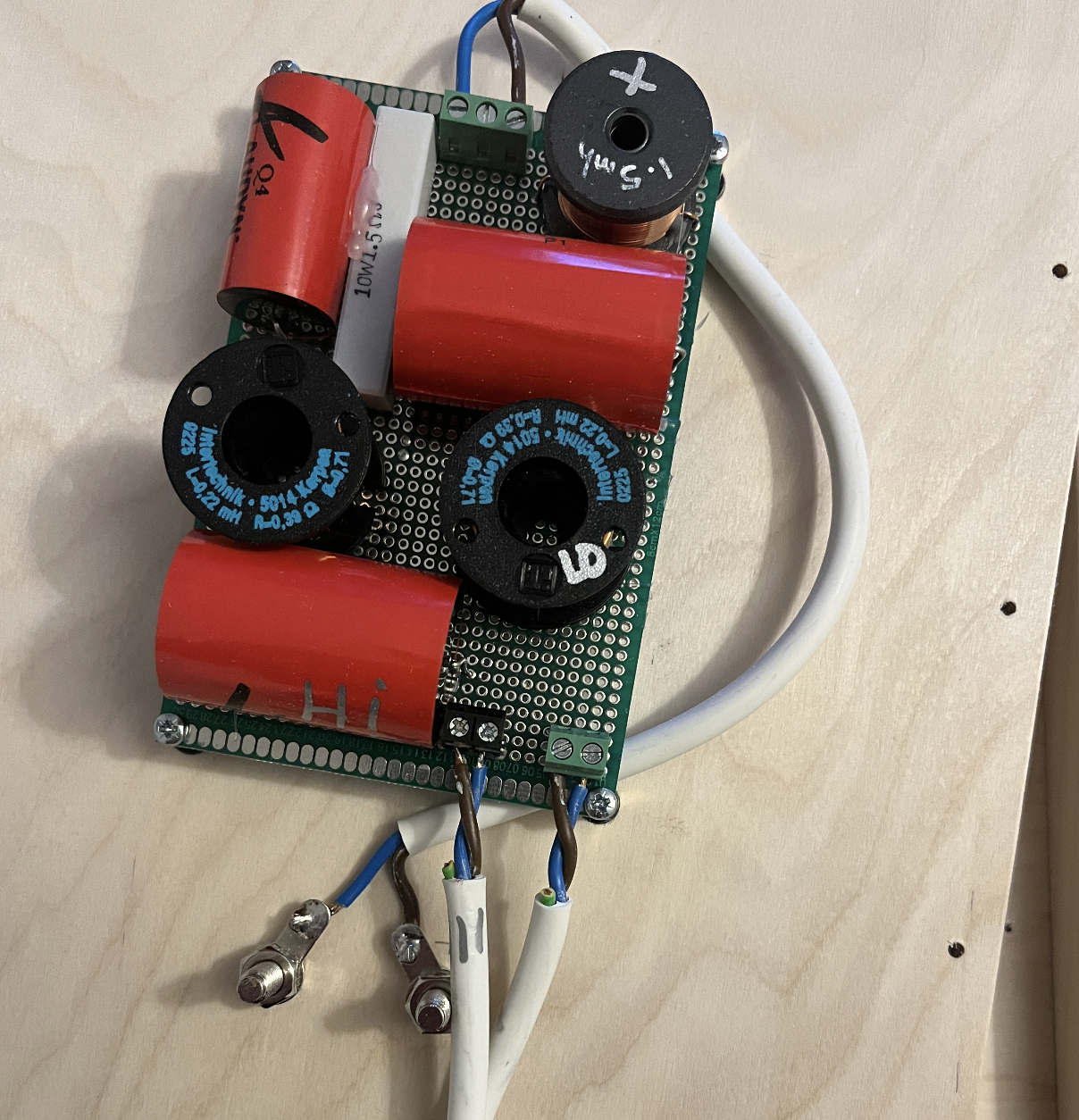
- Crossover Parts:
- I built the crossover suggested specified by SB Acoustics using what seemed like crazy giant components, all from Willys Hifi again. The parts cost about £50(!), half that on six polypropylene capacitors alone. Electrolytic caps would have been much cheaper:
- HiFi Crossover Inductor 1.5mH Iron Core × 2
- 0.22mH Audyn Crossover Inductors, Air Core, 0.71mm OFC Wire, 3% Tolerance. × 4
- 15uF Audyn CAP Q4 MKP Polypropylene Capacitors 400V 5% × 4
- 5.6uf Audyn CAP Q4 MKP Polypropylene Capacitors 400V 5% × 2
- 1.5 Ohm 10 Watt 5% Ceramic Wirewound Resistor × 2
- All built on two 120x80mm proto boards from Bitsbox.
- Various screw terminals I happened to have in stock.
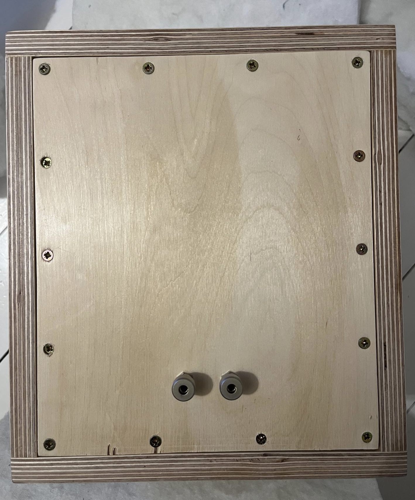
- Monacor BP-420 Nickel Plated Binding Posts × 2
- Gorilla Glue: Worked really well, parts were firmly held after 30-45 minutes clamped, then solid after 24 hours. I didn't use any screws or other fixings, except on the back panel which needs to be removable.
- 90 Degree Positioning Clamps: these are fairly expensive aluminium clamps, copies of the Woodpeckers original which is are very expensive. The squares were essential, but the clamping mechanisms are a bit fiddly. I'd proably use normal clamps with the aluminium squares. If I was being clever, I'd have had some right angles milled out at the wood place.
- Other clamps. These Stanley band clamps were cheap and pretty useful, but two huge Sash Clamps I had from another project were essential.
- I used a Stanley Surform to reduce the thickness of sections where I'd failed to specify the tolerances properly. Sometimes the right tool is just the tool you have handy.
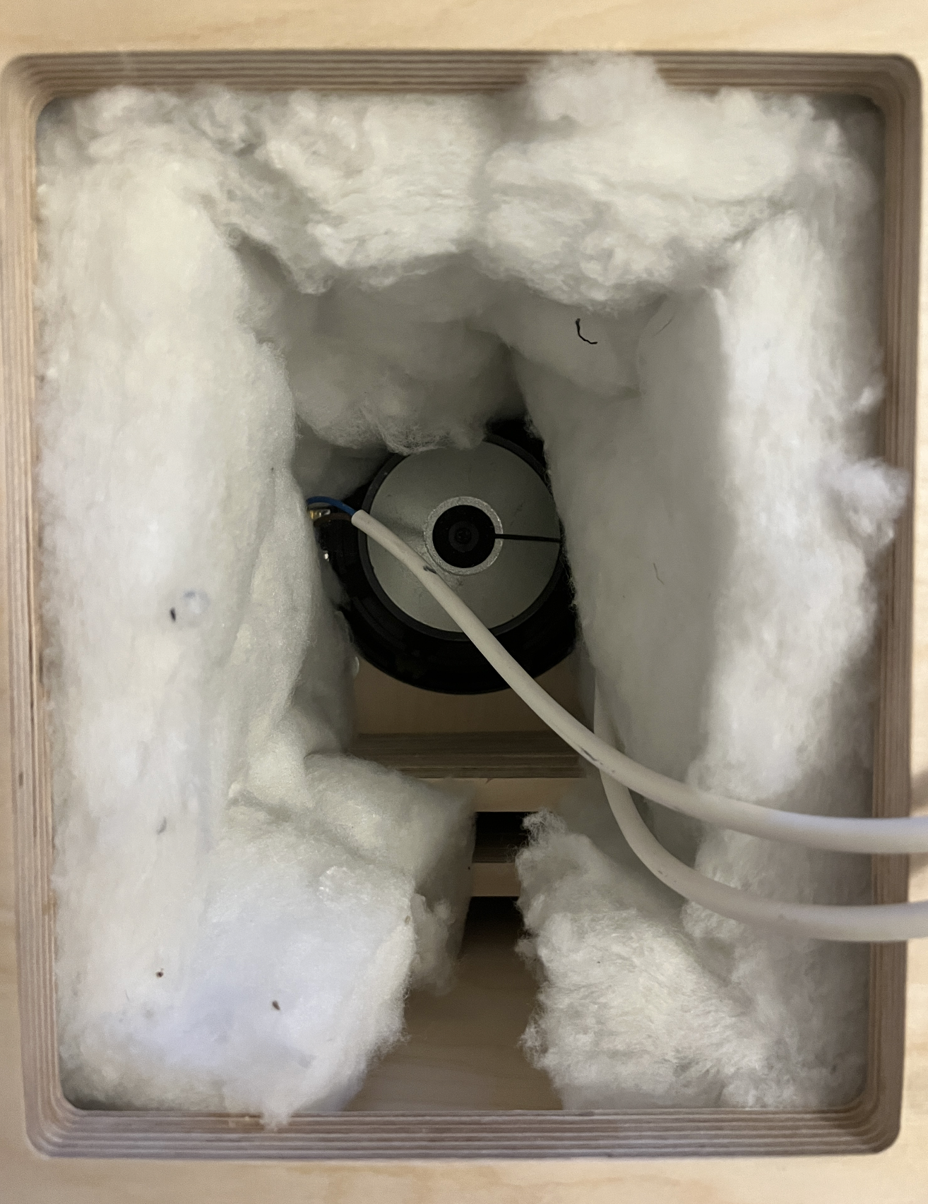
- Recycled plastic bottle insulation I had some of this left over, used it to stuff the box. Seemed to help a bit.
- The driver was found by looking at Lautsprechershop and Willys to find something that was: 6" ish in size, coaxial, not weird looking, suitable for a box about 10-20L in volume, ideally with a lower roll-off around 50hz or lower, costing £50 or less. I wanted something I could mount behind the front baffle, like the Ojas, but that wouldn't work for the SB Acoustics which was otherwise good.
- The box was designed in Illustrator, output as a DXF file, and sent to Hub Workshop which is just up the road from me. They cleaned up the files and allowed for the tolerances to a certain extent (see below)
- The design was based on tracing the Ojas dimensions, doing a lot of chaotic calculations in a spreadsheet (the sheet is here, don't rely on anything), testing different dimensions in this Bass Reflex Box Design tool - the variables come from the speaker specifications.
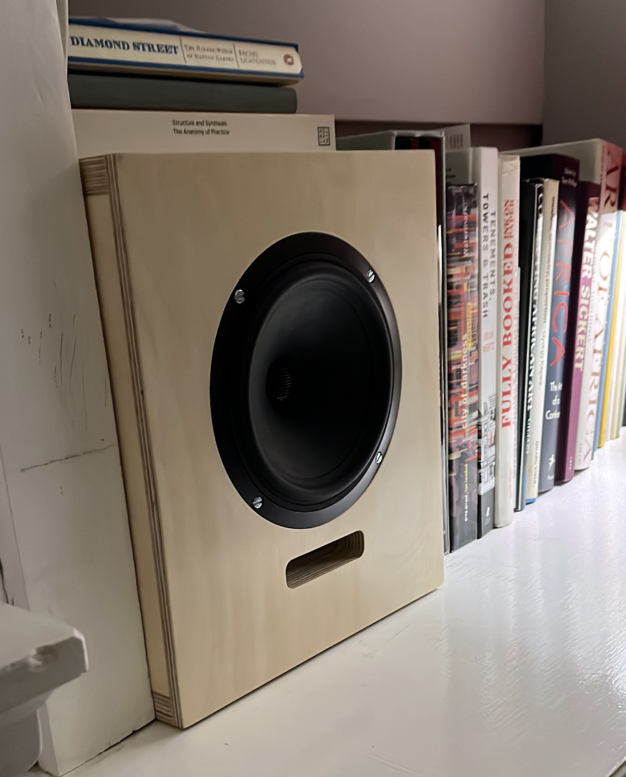
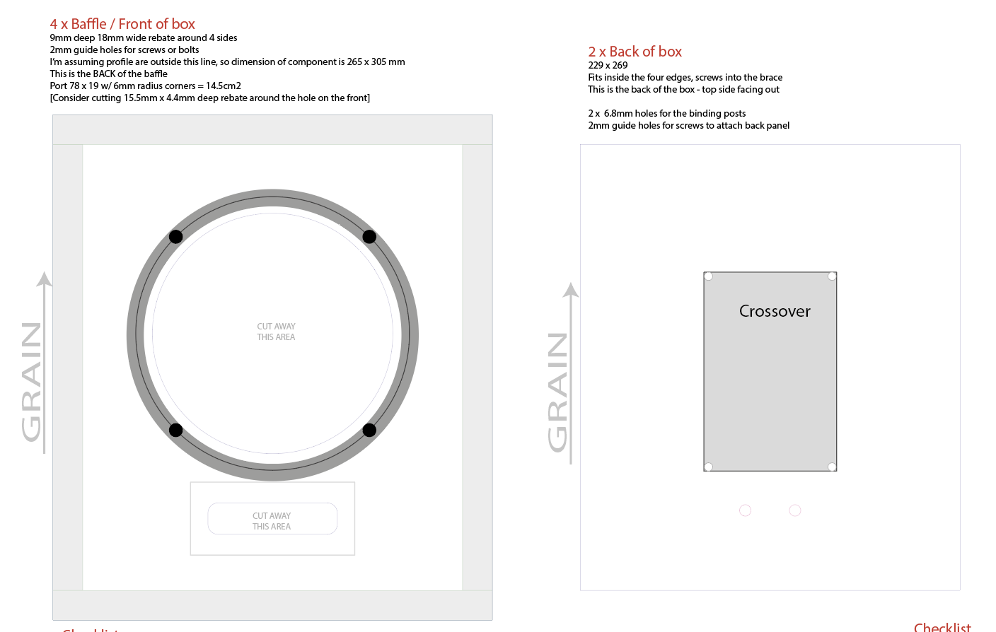
- After a bit of pondering I decided on an 18mm box that was 365 x 305 x 295mm. the baffle (front) is rebated so the sides aren't visible. There's a brace at the back to make it stronger and for the back to screw into. That leaves roughly 16L of internal space.
- I did everything with super simple butt joints. It seems to be fine, I don't see the thing falling apart. Ojas uses Lamello Cabineo connectors which look really clever - they can be CNC milled without drilling the edges of the sheet, and mean you don't need all the clamping, which would be great.
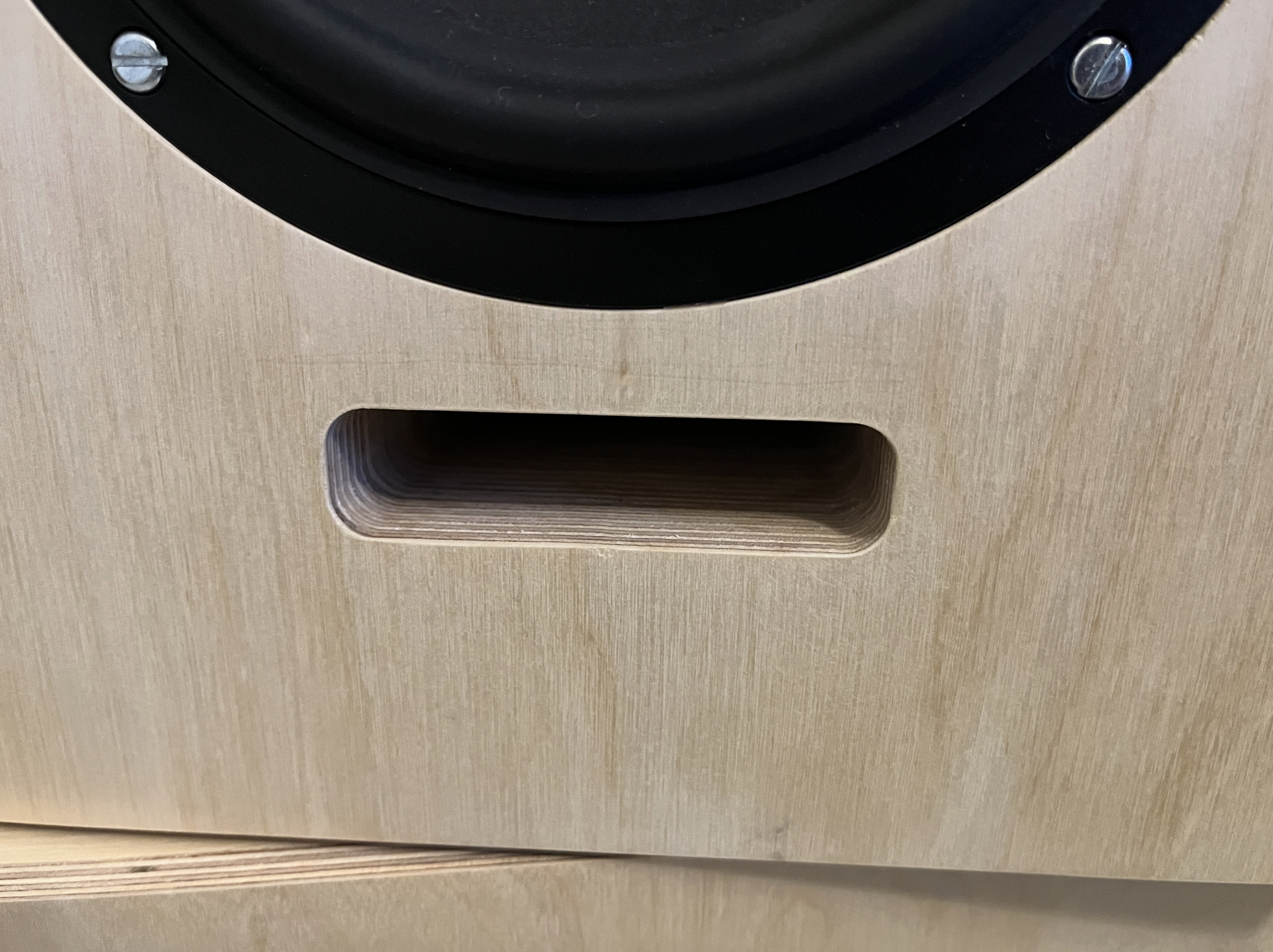
- The vent in the front is 78x19mm with 6mm radius corners, giving it a surface area of 14.5cm2, which (I think) is the same as the HP50 reflex tube specified by Lautsprechershop for this driver. 6 layers of 18mm wood gives 108mm of reflex tube. (I'm sure a speaker design expert would do all this differently.
- In illustrator, I created a separate layer for each tool and depth: One layer for 2mm drills that are 9mm deep. Another for a 6mm endmill bit that goes down 3mm. I just marked the areas to be milled or cut, with lots of annotations in a separate layer to explain what I was up to.
- I created one of each part, with an annotation to explain how many copies were needed. The CNC place lays everything out on a sheet using algorithms.
- Illustrator was fine, but I'm sure a proper tool like Sketchup or better still a parametric design tool like FreeCad would be much better.
- I thought you could only cut on one side, but I was able to specify a reverse cut - space for the speaker to sit in the front baffle.
- The thing about 18mm plywood is that it's not 18mm thick. It might be 17.7mm or 18.3mm.
- If you design a panel with an 18mm wide slot in it, even if it's perfectly cut, one board will fit right in, another won't.
- The CNC place allows for this - they told me: "make all drawings to the exact dimensions of the material thickness (e.g. 18mm). We will then measure the material thickness (they vary per batch) and add tolerance to your design where necessary (i.e. joints). We usually add a 0.2mm offset."
- This worked perfectly in some places - like the rebate cuts around the front baffle. In others, it didn't - the slots to hold the brace were exactly 18mm wide, so I had to plane down the wood to fit in. The back panel was far too snug to fit so had to be crudely planed down. Fortunately, it's invisible once the speakers are in place. I'm sure this was human error on my side, not being clear enough about specifications.
- This is why you shouldn't take my AI file and send it to a CNC place to get your wood cut
- The next time I design a box I'll be much more explicit - referring to nominal sizes and making it clear where sizes need to change.
- Assembly was pretty straightforward apart from the annoying size-fixing.
- First of all I attached one layer of the vent to the front baffle. The whole vent assembly was a bit fiddly — next time I'll use dowels or something to make it easier to stack up the little slices.
- I started by clamping the base to one of the sides - clamping to ensure a perfect(ish) right angle and smooth corners.
- After a few hours I unclamped and did the other side in the same way.
- Next I did the top and the brace
- Then finally the front / baffle.
- It was very satisfying, all worked well. I sanded everything down with a rotary sander, installed the driver and hardware, wired it all up, put on a couple of layers of wax and some stick-on silicone feet, then did it all again for the second box.
- I still hadn't assembled the full vent / reflex tube because I wanted to check if it made a difference.
- I left one box as-is (with just one layer of tube - i.e a 32mm vent. In the other box, I taped together a 108mm tube with fiberglass tape, and stuffed the box with polyester foam.
- Testing the two speakers side-by-side with a switch in the speaker cable, there was definitely a difference. The stuffed, full-tube box sounded deeper and — I think — smoother. I could measure few dB increase when playing test tones in the 40-50hz range.
- So I glued in the full length tubes and stuffed both boxes.
- Installed, I'm really happy with the speakers. They sound good with everything I've played through them.
- As soon as I'd finished them, I wanted to make some more.
- I'd like to try some smaller ones, I'd like to try some bigger ones, but I don't have the space.
- Remember to buy nice black M4 bolts, swapping these over was a chore.