This project is a physical and portable LED sign in the shape of the Counter-Strike : Global Offensive (CS:GO) team Astralis' logo. It is based mainly on the FastLED library as well as the programmable WB2812B LED lighting strips. Everything powered by an Arduino Nano and a portable power bank.
This readme file aims to go through the entirety of the projects' individual parts such as:
- How the sign is constructed
- The circuitry and the individual components
- The code and how it connects everything together
The main part of the sign is made from wooden particle board, which has been cut out in the shape of the outline of the Astralis logo. The cutout measures 50 cm in height and 40 cm in width. The handle consists of a 2,1 cm by 2,1 cm wooden beam wrapped in duct tape for improved comfort when holding for an extended amount of time.
The control box - which the physical interface is attached to - is made with makercase.com, that can generate a cutout of a given shape - in this case, an open box - with different measurements that can be exported as an SVG file. This file is then imported into Adobe Illustrator, where the final details are added, such as text engraving for the controls and cutout for the buttons. The control box is then cut by a laser cutter and finally glued together with wooden glue. See under the images folder for images.
The components used to make the sign work is as following:
- Arduino Nano
- WS2812B adressable RGB LED strip
- 7-segment display
- 74HC595 Bit Shift Register
- Push button
- Potentiometer
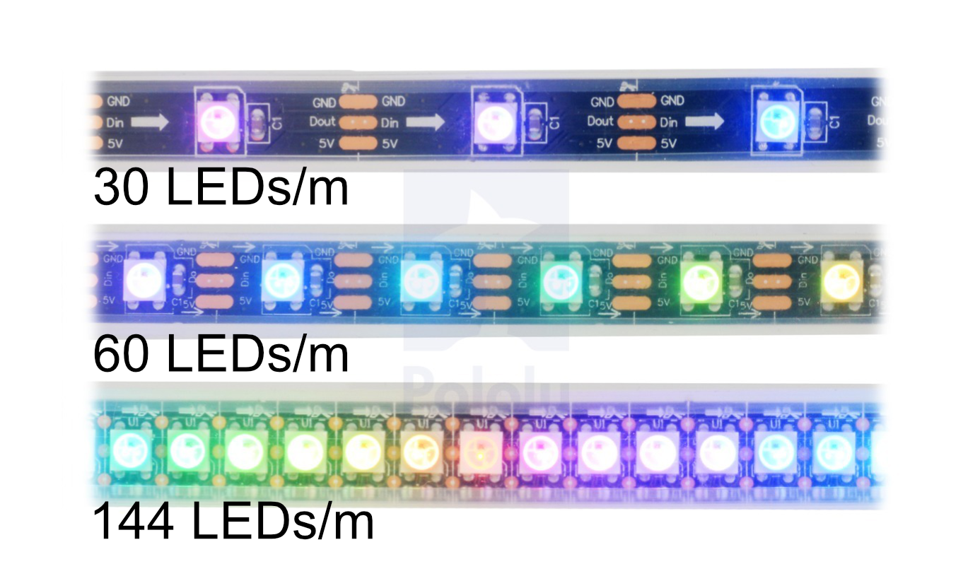
The core of this project is to be able to light the sign itself in different kinds of lighting sequences. The WS2812B addressable LED strip comes in several models that differ in size, sealant, or LED density. For this project, I used a density of 60 LED's per. meter with no water resistance since it is going to be used indoors during matches. The strip is glued with double-sided tape directly onto the board. It is fed with 5v directly from the power bank supplying the power for all components in this project, as well as a 1000 μF capacitor to spare the first LED's on the strip for a potential surge of power, frying them. You can read more here.
This display has nothing more than 8 LED inside. It is separated into segments that are named as a,b,c,d,e,f,g, and DP and can be lit in different combinations to represent the Arabic numerals as well as a dot (DP). This GIF shows how each LED is addressed:

In order to quickly identify which lighting sequence the sign is running, the number can be read out rather quickly as it is located next to the sequence button on the back. When the sequences loop, the number will start back at '1' to indicate that the sequence has reset. As a failsafe, the display is programmed to show an 'E' if an error should occur.
The number shown is determined by how many bits are sent via the 74HC595 bit shift register, which will be elaborated on in the next section.
You can read further into the 7-segment displays as well as other uses on this link.
Normally, in order to control every LED in the 7-segment display, it would require each pin to be connected to the Arduino. This way, you would quickly run out of pins if you were to have multiple digital pins in use. This is where the bit shift register comes in handy. With a bit shift register connected in series, we can accomplish the task of controlling up to 8 LEDs by only using 3 I/O pins. And not just this; you can save even more pins the more shift registers you have chained multiple together if you'd like to control more displays. For this project, a single digit is enough.
The 595 has two registers (which can be thought of as “memory containers”), each with just 8 bits of data. Depending on what data you send to the 595, the data will first be stored and only transferred to the output pins once the 595 is latched.
You can read a more in-depth explanation about the 74HC595 in this detailed guide.
The idea of the sign itself it that it stores multiple lighting sequences, which you can switch between with a simple push-button. The main idea is that by a single push, the sign should go to the next lighting sequence once the button is pushed and released. Buttons come in many sizes and shapes, but many of them share the same issue in regards to sending a HIGH or LOW signal. This is commonly referred to as a 'bouncing' signal where the signal quickly jumps up and down multiple times in a short amount of time (typically a few milliseconds). This can be countered by implementing what is called 'debouncing.' The below image is an example of a button being pushed and released, bouncing the signal before settling.
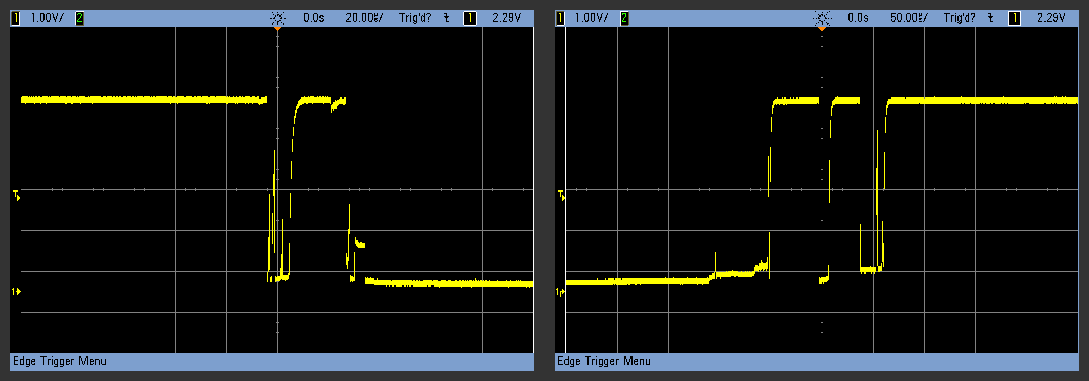
When you physically press a normal push-button, two pieces of metal come into contact with each other. If these two tiny sheets of metal aren’t perfectly flat or perfectly aligned (and they’re not), then they can make and break contact a few times before being firmly enough squished together that they’re always conducting. To a microcontroller, the button appears to be pressed many times for extremely short durations when you think you’ve just pressed it once. Debouncing is all about making sure that you and the microcontroller agree about when a button push or release event happened. This is how a button push is registered without any form of debouncing.

The simplest hardware solution, which is shown in the image above is to debounce with a 10K ohm resistor and a 1μF capacitor. For this project, the debouncing feature is critical for the reason being that the sign has multiple lighting sequences stored. If the button registers multiple 'pushes' in one, the sequences would quickly cycle through, resulting in an incorrect cycle.
For a more detailed explanation you can read further here.
On the far left on the control interface, it is possible to control the brightness of the LED's. This is done by using a potentiometer, which acts as a variable resistor and commonly used to control electrical devices such as volume controls or, in this case, lighting. Depending on how much the potentiometer turned, the resistor is only letting a part of the total current, though, which can be read via an analog signal. How this signal is read and used will be further explained in the software section.
For a more detailed explanation on how a potentiometer works you can read more here.
The code for running the WS2812B LED strip is made with the help of the FastLED library. The FastLED library is an easy and fast way to light the individual LED's up in the order you wish as well as generating lighting patterns.
The lighting effects are primarily based upon this website, demonstrating a handful of effects as well as the code and setup. These effects are based upon the concept of for loops and is a good way to run these effects. However, this project implements the addition of a button to change between effects, and this feature comes with one issue. The for loops 'occupy' the running code and only continues when the loop is done. Therefore, if you push the button while the for loop is running, the push will not register.
Because of this, the effects used have been rewritten in order to counter this issue by using global variables and reduce the number of for loops used.
The two examples shown below makes the same effect, but are written in two different ways. The first one is the original effect and does not register a button push while running, whereas the second example does because it is utilizing global variables, which can be used outside of the function theaterChase.
Example one:
void theaterChase(byte red, byte green, byte blue, int SpeedDelay) {
  for (int j=0; j<10; j++) {  //do 10 cycles of chasing
    for (int q=0; q < 3; q++) {
      for (int i=0; i < NUM_LEDS; i=i+3) {
        setPixel(i+q, red, green, blue);    //turn every third pixel on
      }
      showStrip();

      delay(SpeedDelay);

      for (int i=0; i < NUM_LEDS; i=i+3) {
        setPixel(i+q, 0,0,0);        //turn every third pixel off
      }
    }
  }
}
Example two:
int theaterDistance = 3;
int theaterDelay = 300;
int theaterJ = 0;
int theaterI = 0;

void theaterChase(byte red, byte green, byte blue) {
  if (theaterI == 0) {
    for (int i=0; i < NUM_LEDS; i++) {
      setPixel(i, 0,0,0);
    }

    for (int i=0; i < NUM_LEDS; i+=theaterDistance) {
      setPixel(i+theaterJ, red, green, blue);    //turn every theaterDistance pixel on
    }
    showStrip();
    theaterJ = (theaterJ + 1) % theaterDistance;
  }
  theaterI = (theaterI + 1) % theaterDelay;
}
The brightness of the LED's is controlled via a potentiometer, as discussed. The signal is read initially as a value from 0 to 1023. The FastLED library only works with numbers from 0 to 255 in order to define the brightness. The numbers will then need to be mapped with the map function, as shown below and then constrained with the variables MIN_BRIGHTNESS and MAX_BRIGHTNESS, which is used as limiters.
  int brightnessValue = map(analogRead(brightnessPin), 0, 1023, 0, 255);
  FastLED.setBrightness(constrain(brightnessValue, MIN_BRIGHTNESS, MAX_BRIGHTNESS));
As discussed in the Deboucing section in Hardware, buttons have a tendency to generate 'noice' when pressed and released. The code below checks twice in a short period of time to make sure the pushbutton is definitely pressed.
The button push hereafter increments sequenceNumber by one, and runs the lighting function corresponding to the number. It also clears any data that should be remaining in the LED's with setAll(0, 0, 0); and shifts the correct number to the 74HC595 to light up the corresponding sequence number on the 7-segment display.
 // LED lightning sequence control
  buttonState = digitalRead(buttonPin);

  if (buttonState != lastButtonState) {
    if (buttonState == HIGH) {
      sequenceNumber = (sequenceNumber+1) % 5;
      writeAndShift(sequenceNumber + 1);
      setAll(0, 0, 0);
    }
  }
  // save the current state as the last state, for next time through the loop
  lastButtonState = buttonState;
Finally, the Arduino needs to know which lighting sequence to run depending on the sequenceNumber variable. This is done by using switch and case statements. These work just like if statements but are much nicer to look at. switch(sequenceNumber) is used to define which declaration should be used for the case statements. The case 1: will run if sequenceNumber equals 1, case 2: if sequenceNumber equals 2 and so on. Under every case, you define what code should be executed.
 switch(sequenceNumber){

    case 0:
      FadeInOut(0xff, 0x00, 0x00); // Only using red
      break;
default: is used as a failsafe, should the value go beyond the given case statements. Much like the else statement, you define what should be executed, if none of the above statements are true.
This project is licensed under a Creative Commons Attribution 4.0 International License.
I would like to personally thank Duckapple and Jlndk for helping me with the code.