- Correct web template usage
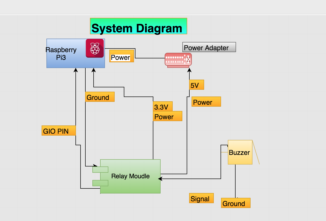
- Introduction using a system diagram
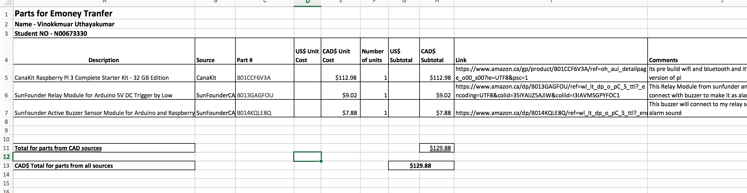
- Bill of Materials/Budget
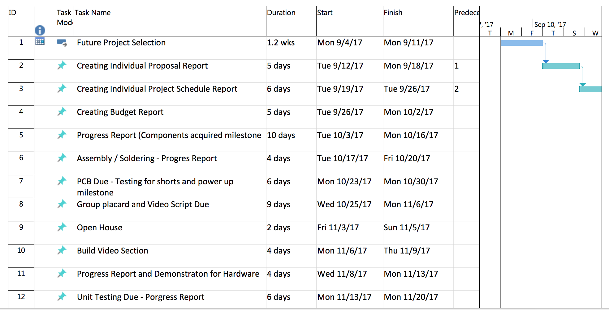
- Time Commitment
- Mechanical Assembly
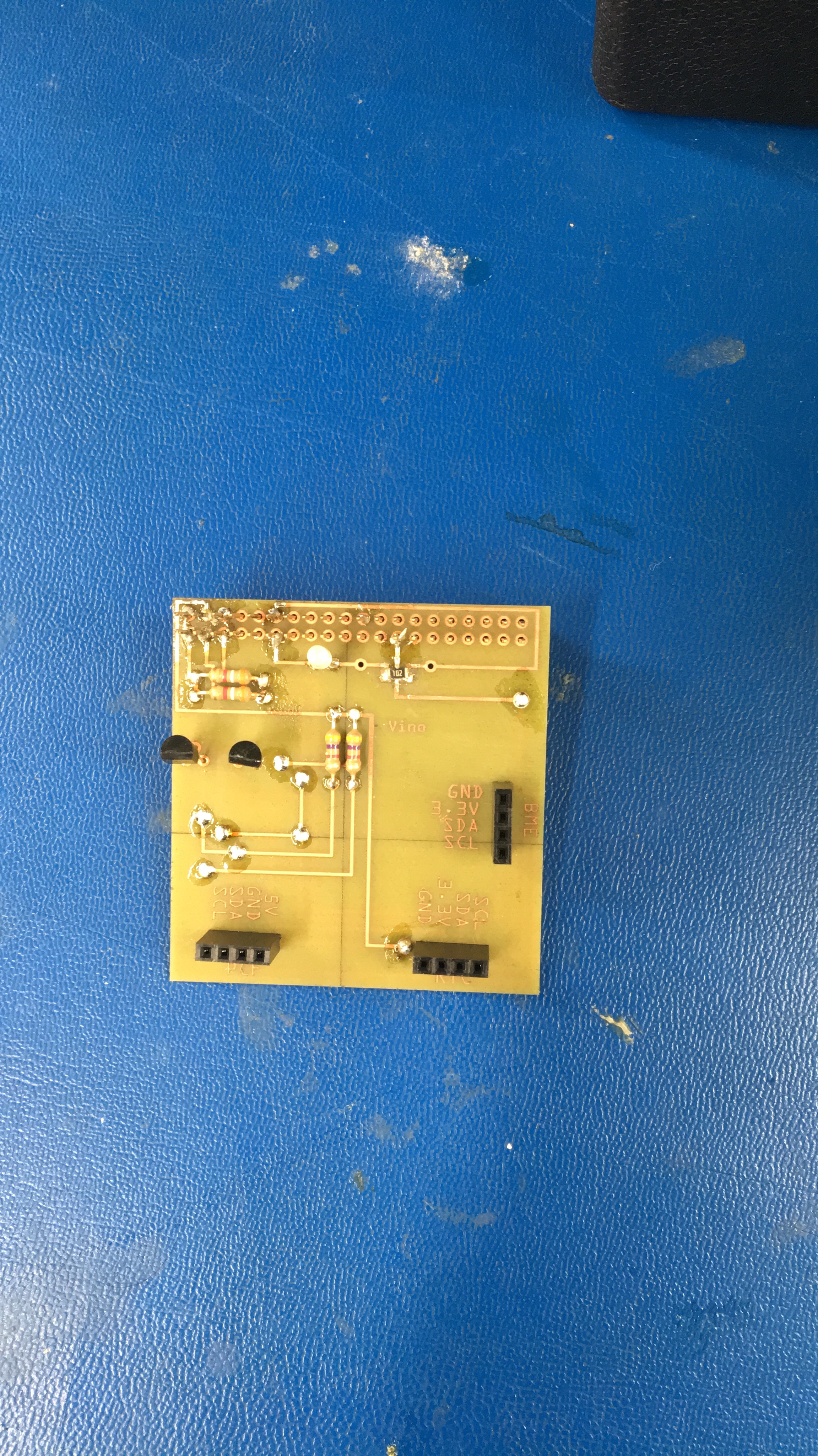
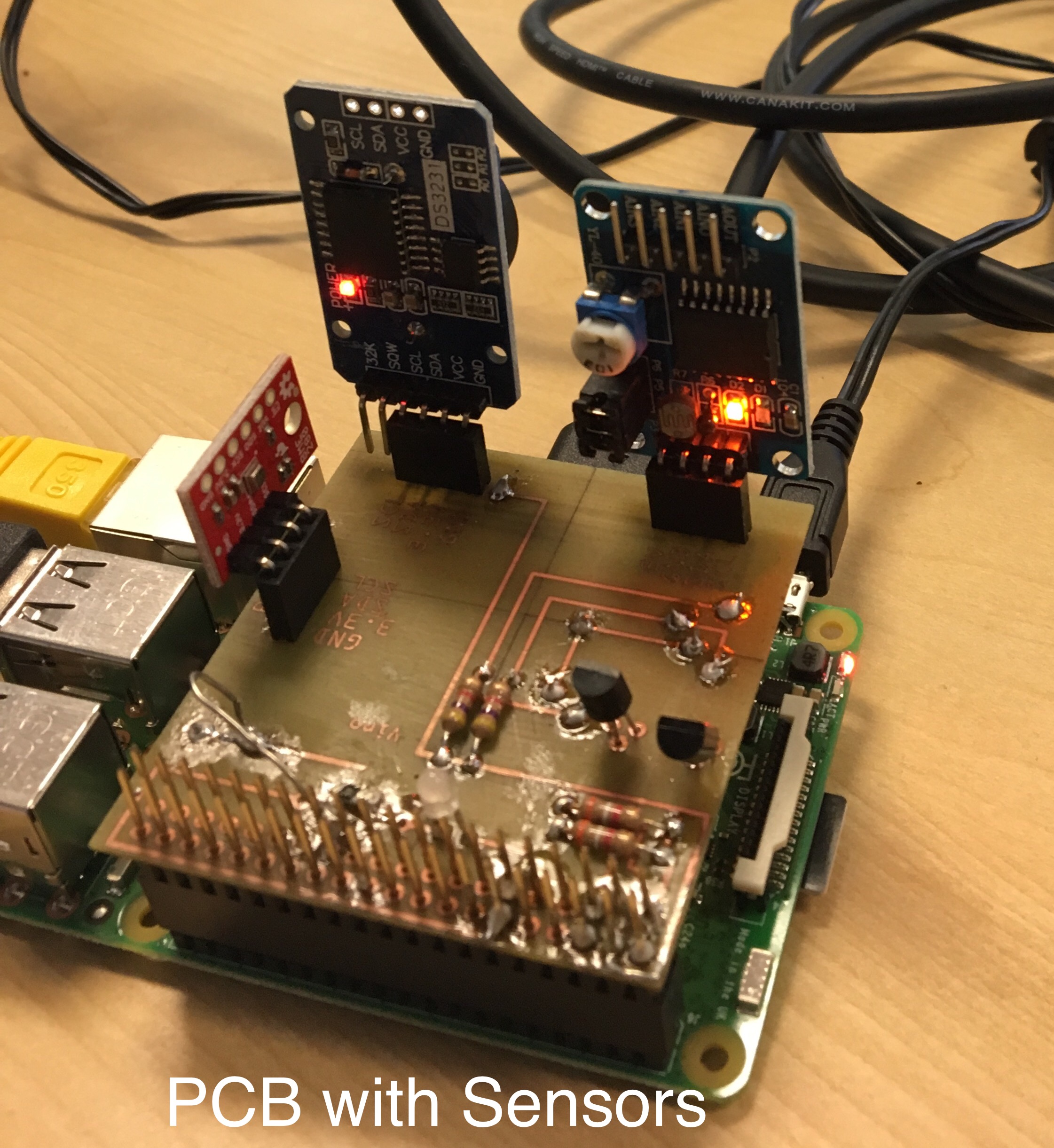
- PCB Soldering
- Power Up
- Unit Testing
- Production Testing
In the Beginning, I had created the repository for this project to uplaod all my work and I had to create index.md which is where I uploaded the work I do every week. The Template provided by my Project Instructor. And In Readme.md, I am doing build Instruction, I got template from my Professor. My webpage built in Mark Down langauage. I published whatever I was doing evey week. There are pictures and reports about my project.
- Support control of DC and AC signals (AC 220V load).
- Working voltage: 5V; PCB size: 2.0 x 4.3 cm.
- With power light and signal output indicator.
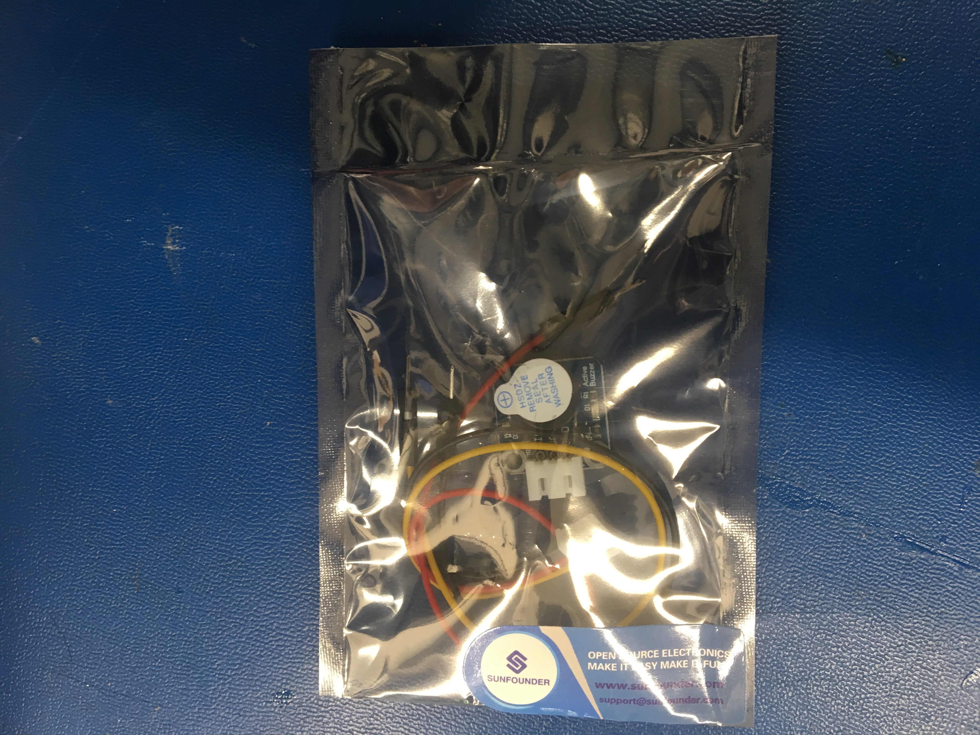
- A 3-pin anti-reverse cable included.
In E-money transfer, I am using relay module as my sensor. I’m using this sensor for security purposes. I am going to connect my relay module to raspberry pi3 and I also have a buzzer which is used to indicate the output of the relay module. The relay module will detect if the payment has done or not with the barcode created by my app from software. Once it detects that product has been stolen then the buzzer will go off indicating that the transaction has not been made. By this way we can prevent scamming.
Normally, To built this Project It will take about a week but however It took me about two weeks because of the extra requirement from my professor. First, For parts arrival from amazon and It took me about two days. Between that time I was getting knownlage about my parts from SUNFOUNDER.COM. Secondly, To Mechanical Assembly, I have spend about a day to assemble everything together. Because I was Working on Software requriment and also builting PC Board, so that took me another two days.Thirdly, To make my sesnor work I have to write program and then that took my two days. I have worte the program in Python. Finally, I have made my sensor connected to pi3. So It was almost two weeks to complate entire project with all the spefication and requriment from Instructor. If you follow these instructions, It will take only a day to complate.
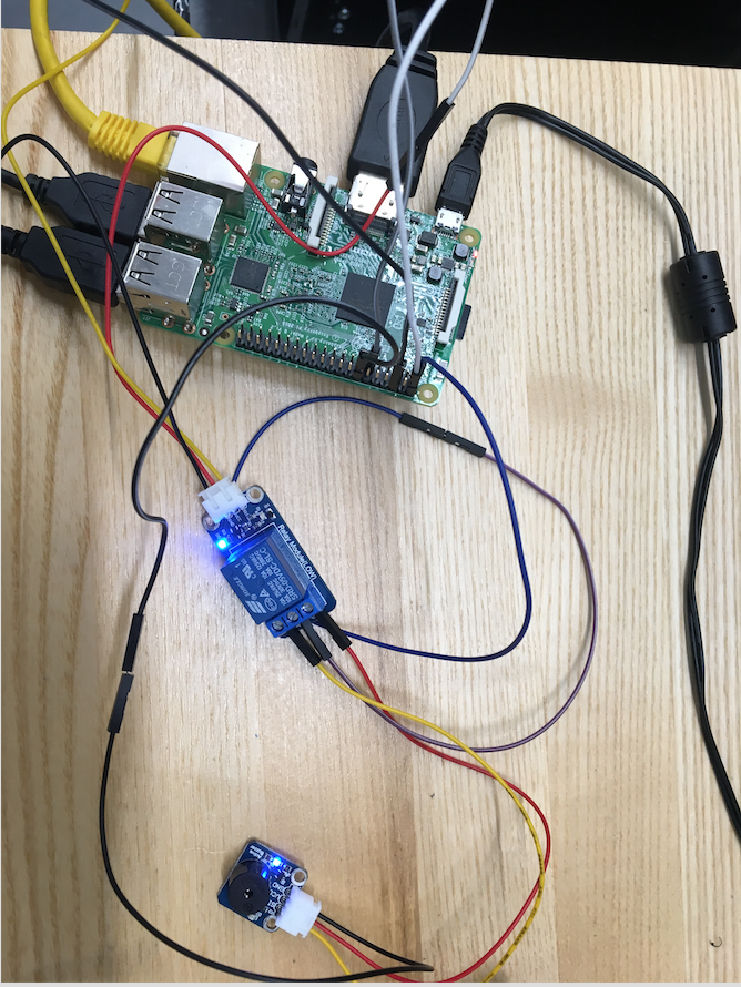
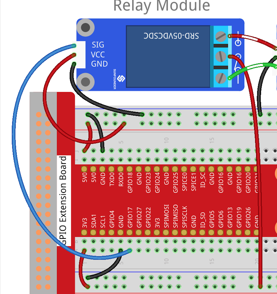
My Relay module sensor was acting like an alarm. To build this, I was required raspberry platform and also a buzzer that indicate that output from relay. First, I have installed raspbian OS on rasbperry pi3, so I am able to run the program to connect my module over the pi3. Secondly, I was connecting my Relay module to rapsberry, I connect the signal from relay module to GIO pin in Pi3. Secondly, I have to supply the power to my relay module so I was connecting 3.3v volatage pin in raspberry pi to the VCC in module (I AM PROVIDING 3.3V TO MY REALY MODULE BECAUSE IT IS A LOW LEVEL MODULE, THERE IS A HIGH LEVEL MODULE AND IT REQURIE 5V VCC PLEASE BE AWARE). And then I was connecting a ground pin in pi3 to module ground, so now I was able to make a connection from my relay module and pi3. Finally, I was connecting my buzzer to my relay and I connected the ground from buzzer to pi3 ground pin, and the signal from buzzer It connected to the relay module output, and then I provided 5V to the buzzer from raspberry pi3 pin and it started working as an alarm when I execute the python program. PYTHON Program
I soldered PCB board to add more senors.
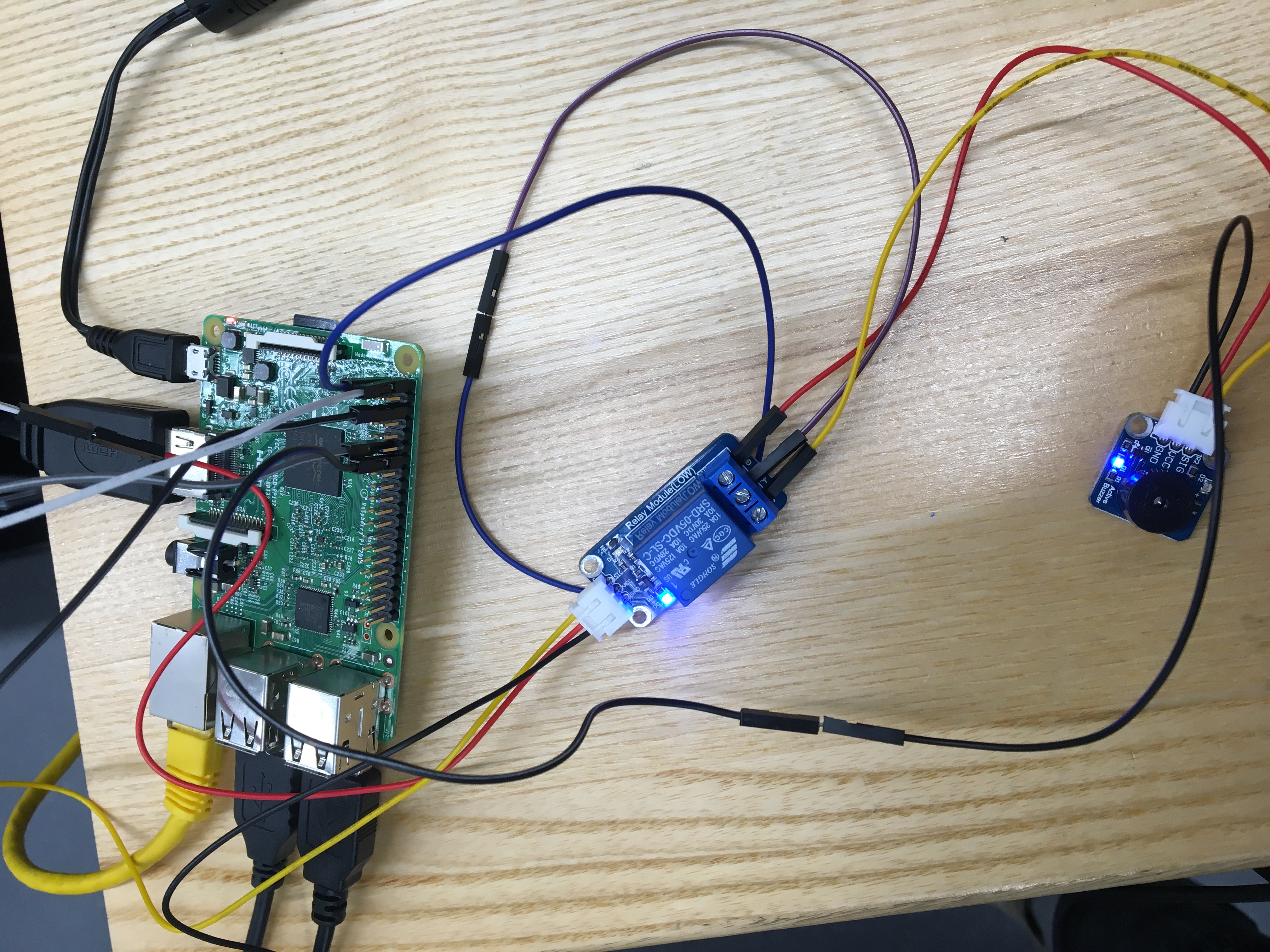
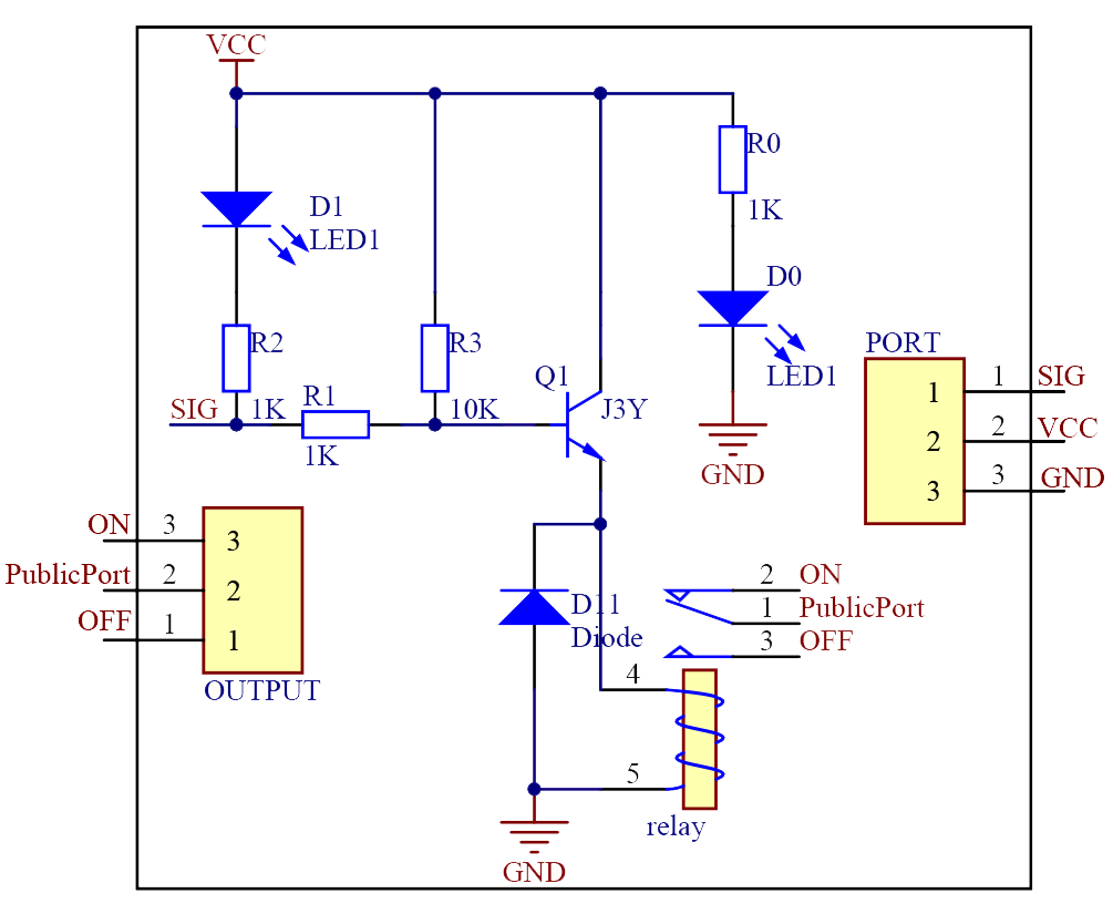
Connect the base electrode of the transistor to GPIO0. When we make GPIO0 output high level (3.3V) by programming, the transistor will conduct because of current saturation. The normally open contact of the relay will be closed, while the normally closed contact of the relay will be broken; when we make it output low level (0V), the transistor will be cut off, and the relay will recover to initial state. The schematic diagram of the module is as shown below:
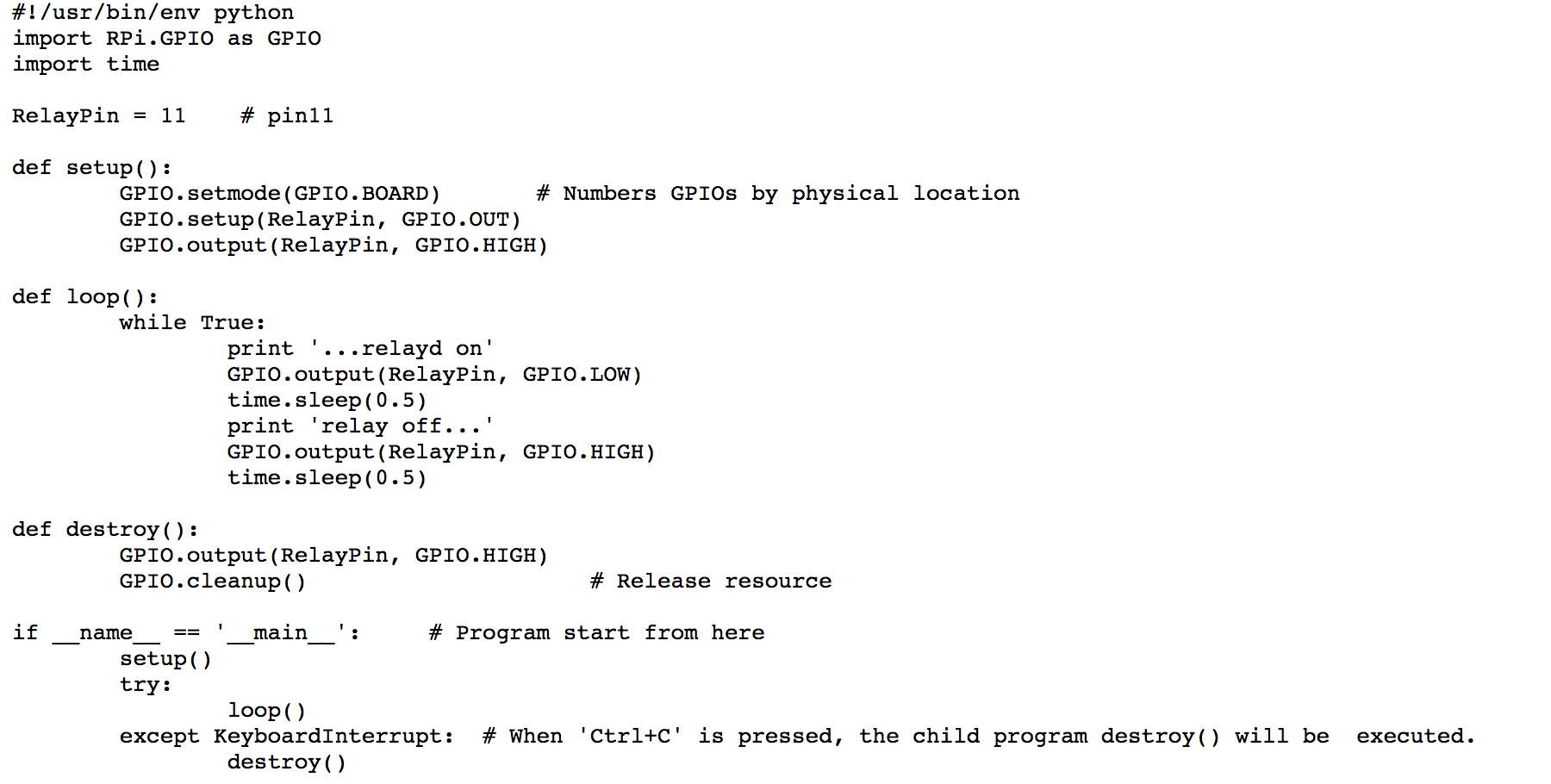
For Python users: Step: Run sudo python relay.py
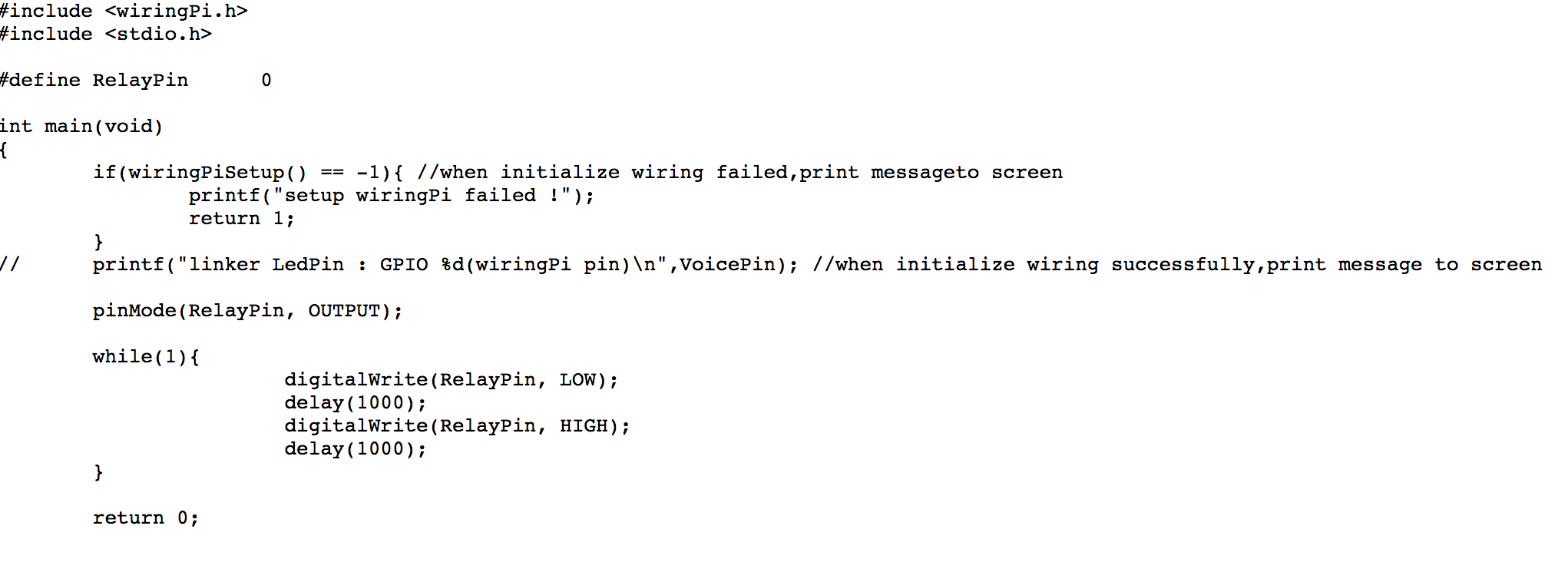
For C user: Step 1: Compile gcc relay.c –lwiringPi Step 2: Run sudo ./a.out
you may hear the ticktock. That's the normally closed contact opened and the normally open contact closed. I attached the buzzer so it can make noise like alarm.
** Thank you **