mapamok (English)
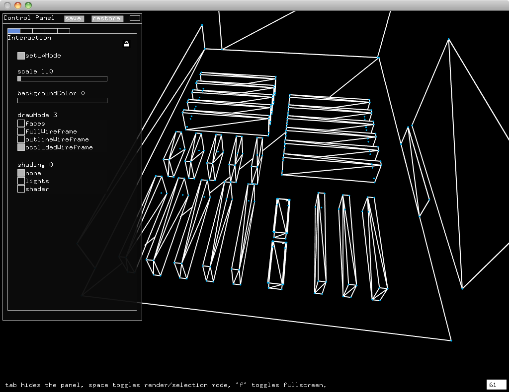
This picture shows a screenshot of mapamok running using a model of the YCAM Library.
mapamok is an experimental application for exploring some new ideas about projection mapping.
- Calibrating projectors shouldn't take so long.
- Think less about the projection, and more about the space.
- Prototyping ideas should be instantaneous.
These ideas are approached from a few perspectives:
- Fast projector calibration, borrowing techniques from camera calibration, cuts calibration time down to one minute.
- Always working with a 3d model instead of a 2d mask or mesh.
- Sketching up ideas with auto-reloading GLSL shaders.
This tutorial describes how to use mapamok, and how to develop it. The development section assumes strong familiarity with openFrameworks and OpenCV, while the usage section tries to explain details in the simplest terms (though some topics are still too complex to cover here).
mapamok can be downloaded here. It's currently OSX 10.6+, but there are no significant barriers keeping it from being compiled for other platforms.
When you unzip the download, you'll see mapamok.app and a data/ folder. Inside the data/ folder. Inside data/ is a Collada 3d model called model.dae, and two GLSL shaders called shader.frag and shader.vert.
The general idea is to first prepare a model of the scene you are projecting on. Then replace the original model.dae with your own. Finally, start up mapamok.app, walk through the calibration process, and try some different visualizations with the shaders.
Download and install Google SketchUp. We're going to build a simple model using a collection of cubes.
First, delete the person that is standing in the middle of the screen by selecting them and hitting "delete". If you have a tool selected, hit the spacebar to go into selection mode first. Hit o to go into orbit mode. Drag the camera around to get a better perspective of the center of the scene. Rotate by dragging, pan by shift-dragging, zoom by scrolling.

Click on the Rectangle tool or hit CMD+K. Move your mouse to the center of the axes and a yellow dot will appear, snapping your cursor to the center. Click once, then move your mouse away from the center, and you will see a rectangle expand. Don't click again, just type "500mm, 500mm" and hit enter. This will create a rectangle that is 500mmx500mm.
Click on the Push/Pull tool or hit CMD+=. Then select the top of the rectangle you just created by clicking on it. Start pulling the top upwards, and without clicking on anything just type "500mm" and hit enter. This will turn your rectangle into a cube that is 500mm on every side.
Click the selection tool, then click and drag to select the entire cube. Copy, then paste the cube. When you paste, your mouse will be attached to a corner of the cube and you will be able to place the pasted cube. Line it up with the other cube's corner, and the new cube will snap to the old one. Paste again and place another cube. Repeat this process until you've replicated the cube model you are projecting on.
Finally, save the SketchUp file using File > Save. Then export your model using File > Export > 3D Model. Select "COLLADA File (*.dae)" from the file format dropdown. If you click on "Options", I normally only have "Triangulate all Faces" and "Preserve Component Hierarchies" selected. SketchUp doesn't always handle groups well during export, so be careful about what you group. Save the file as model.dae and drag it into the mapamok data/ folder.
If you're loading a model from someone else, instead of creating it from scratch, you will need to use the "Explode" command in SketchUp to ungroup all components of the model. Also, transparent materials are not exported from SketchUp, so make sure any transparent surfaces are filled with an opaque color. One way to guarantee that you can load a model into mapamok is to export it from SketchUp as an STL, and then convert it from an STL to COLLADA using MeshLab.
One of the goals of mapamok is to make simple cuboid-style projection mapping so simple that it becomes completely uninteresting. Cubes are just the easiest kind of model to explain, but SketchUp can be used for modeling a huge variety of solids. If you have other kinds of data to start with, like 3D scans, point clouds, etc. then you might want to use other software besides SketchUp to create your model.dae.
When you open mapamok, it will immediately go full screen. There are two modes: "render" and "selection". By default you are in "selection" mode. Controls are in the control panel on the left hand side, and there are also four keyboard shortcuts:
-
tabtoggles the control panel visibility -
spacetoggles between "render" and "selection" mode -
ftoggles fullscreen -
swill save the projector intrinsics after calibration
If you forget any of the first three important ones, there is a hint at the bottom left of the screen. At the bottom right there is an FPS counter that should be approximately 60 fps on any normal computer.
The control panel has two buttons for saving and restoring the settings from a data/settings.xml file, and five tabs containing different options.
- Interaction Most commonly used options.
- Highlight Rendering effect useful for testing vertex ordering.
- Calibration Low-level projector calibration settings.
- Rendering Modify the appearance and feeling of the app, mostly in render mode.
- Internal Reports internal status, and some options for modifying the feeling of selection mode.
You don't need to pay attention to anything but the first tab.
- setupMode This controls whether debug points are drawn in render mode. After you're done with calibration, you can disable this.
- scale Normally, you should use right-click-drag to zoom in and out of the model, but on some systems this is difficult. scale provides an alternative.
- backgroundColor Sometimes when you're calibrating a projector, it can be helpful to have some extra light being cast.
- drawMode and shading Each of the drawing modes renders your polygons in a different style, and the shading modes control whether everything is drawn in white, with lights, or using a custom shader.
This feature is mostly for debugging purposes.
- highlight Controls whether highlight mode is enabled. Highlight mode will render a subset of your scene.
- highlightPosition and highlightOffset control how much of your scene is rendered.
The "position" refers to the vertex numbers as they are given in the COLLADA file, rather than the spatial ordering of the vertices.
Almost all the time, these options can stay set to their default values. If you are using an extremely wide angle projector lens, or a projector lens that is extremely unusual in some other way, you may need to tweak these settings. The details of these settings are beyond the scope of this documentation. Details are available in the OpenCV documentation.
If you have a very high quality lens with zero lens shift, you may want to enable CV__CALIB__FIX__PRINCIPAL__POINT.
CV_CALIB_ZERO_TANGENT_DIST is enabled by default because most projectors have very little tangential distortion compared to cameras.
If you have an extremely wide fisheye lens, or a lens with a lot of radial distortion, you may need to enableCV_CALIB_FIX_K1, CV_CALIB_FIX_K2 CV_CALIB_FIX_K3.
CV_CALIB_FIX_ASPECT_RATIO should always be set to true unless you have an extremely unusual projector with non-square pixels.
These options all control various parameters of how the scene is rendered. If you are using a custom shader, many of them are irrelevant. Here are two things that might be interesting.
- Fog is enabled with useFog and tweak fogNear and fogFar
- Lighting can use randomLighting for some interesting effects when using the lights shading mode. Otherwise, you can control the light position manually with the lightX, lightY and lightZ sliders.
You should never have to touch these options. They are all reporting internal information back to the user, with the exception of the last two sliders: slowLerpRate and fastLerpRate. As you drag points around on the screen, this controls how quickly the points follow your cursor. Using left-click-drag is slow dragging. Right-click-drag is fast dragging.
After mapamok starts up and loads your model, the next thing you want to do is calibrate your projector. This should take less than ten minutes the first time, and less than one minute after that.

First, while mapamok is in selection mode, use left-click-drag to rotate your model around until you find a perspective that shows you a view of the scene that is similar to what the projector sees. The selection mode view does not influence the calibration process, so finding a similar perspective is strictly for your convenience.
While looking at your computer monitor, hover over one of the blue points, and it will turn into a larger magenta point with a number label. Click to select it, and it will turn yellow. Now hit space to toggle from selection mode to render mode. You will see a copy of the point you selected. Still looking at your computer monitor, click on and drag the point. It will turn yellow while you are dragging it.
While dragging the point, look at the real scene you are projecting on. Drag the projected point until it lines up with the real corner that corresponds to the virtual model. When you are done, hit space to switch back to selection view.
Look back at your monitor, and select another point in the scene, repeating the above process. Once you have selected six points, mapamok will try to make an initial guess about your projector: what the focal length is, where it is in relation to your scene, and how it's oriented, etc. Sometimes it takes seven points, but you should aim for between 8-12 points.
If your model is generally accurate, and your lens is not too distorted, this process will always work. Here are some tips to keep in mind while picking and places the calibration points:
- If it looks like the model wireframe does not line up with the real scene, try placing more points. You shouldn't need more than 12 points to get a good calibration.
- If your calibration still doesn't line up, make sure to check that your points are lined up with the correct corners of the real world. If one or two points are wrong, it can skew the calibration in strange ways.
- Try to pick points that cover the whole scene, including the center and the farthest edges of the scene.
- Don't pick multiple points that are close to each other.
- Don't pick too many points that lay on the same plane. In mathematical terms, the points should be as linearly independent from each other as possible.
The suggestions above should help with calibration, but you don't need to understand all the suggestions in order to get a good calibration.
Once you've calibrated your projector, you can export the intrinsics by hitting the key s. In the future, the projector calibration should be exported in a more accessible format (reporting field of view, position and orientation). Right now, the calibration can only be saved, it can't be loaded.
Once you have your model prepared, and your projector calibrated, you can start experimenting with different kinds of shader-based visuals.
There are two shader files: shader.vert (vertex shader) and shader.frag (fragment shader). The general idea is that, as things are being rendered on the screen, first they pass through the vertex shader and then through the fragment shader. The details of GLSL is beyond the scope of this tutorial, but some examples are provided in the fragment shader.
To try different looks, enable the shader mode in mapamok and change this line of code in shader.frag to a different number:
float stage = 0.;
You can change the code while the app is running, and then when you save the code it will automatically update the projected visuals. If you want to cycle through the effects while your app is running, you can use timeElapsed:
float stage = mod(elapsedTime * .6, stages);
At the moment, the only indicator of a shader that has failed to compile is the debug information printed in Console.app. For this reason, mapamok is good for experimentation, but not necessarily intense development. For more complex visuals, it might be better to get started with the OpenGL Shader Builder first, and then copy the code over to mapamok.
Most of the mapamok code is about handling the interface and control panel. All of the hard work is done by addons and shared code:
-
ofxProCamToolkit (part of the ProCamToolkit repo) provides a collection of helpful functions for working between screen space and world space, like
ofScreenToWorld()andofWorldToScreen(). These functions may be rewritten in the future and submitted to the openFrameworks core. - LineArt (part of the ProCamToolkit repo) is almost like an addon, and is used for rendering edge-only and occluded-wireframe shading modes.
-
ofxAssimpLoader loads the
model.daefile, which is stored as anofMeshinobjectMesh. - ofxControlPanel handles the control panel. I'm using an extension to ofxControlPanel called ofxAutoControlPanel that is hosted on my fork of the repository.
- ofxCv provides some calibration classes and methods.
The significant contribution behind mapamok is the idea of using a model of a known scene as a calibration target. Normally when you calibrate a camera (or projector) you use a chessboard or similar repeating pattern. But because camera calibration only requires a correspondence between object points and image points, it is possible to use any known object. When you are using a non-planar calibration target, OpenCV requires you to initialize the camera matrix. This is where the "angle of view" guess from the Calibration tab in the control panel is used (again, the guess is not important, because calibration algorithm will optimize the angle of view):
float aov = getf("aov");
Size2i imageSize(ofGetWidth(), ofGetHeight());
float f = imageSize.width * ofDegToRad(aov);
Point2f c = Point2f(imageSize) * (1. / 2);
Mat1d cameraMatrix = (Mat1d(3, 3) <<
	f, 0, c.x,
	0, f, c.y,
	0, 0, 1);
After you initialize the camera matrix, you can do the standard camera calibration to solve for the projector's intrinsics and extrinsics:
calibrateCamera(referenceObjectPoints, referenceImagePoints, imageSize, cameraMatrix, distCoeffs, rvecs, tvecs, flags);
mapamok also has a significant branch available from GitHub called library. The library branch contains some special features, such as integration between mapamok and the Novation Launchpad, and it supports MIDI output.