Different components configure #3
Comments
|
It's different screen. We use SPI interface while yours is some kind of parallel one. Can you send exact model name of your screen? |
|
As I remember we used this one: https://ru.aliexpress.com/item/2-8-320-240-SPI-TFT/32847628219.html |
|
this is also SPI, I tried to buy the same but somehow it's differnt
Here is the one I bought on ebay:
https://www.ebay.com/itm/223145284611
FX- 2.8" 240x320 SPI TFT LCD Touch Panel ILI9341 5V 3.3V for Arduino RPi
ESP8266
…On Tue, 8 Jan 2019 at 07:46, ZFTurbo ***@***.***> wrote:
As I remember we used this one:
https://ru.aliexpress.com/item/2-8-320-240-SPI-TFT/32847628219.html
—
You are receiving this because you authored the thread.
Reply to this email directly, view it on GitHub
<#3 (comment)>,
or mute the thread
<https://github.com/notifications/unsubscribe-auth/AEuStOGyUaBCx-zo9QIY8Sk2PoD2uYBgks5vA7lJgaJpZM4Zy27n>
.
--
Đoàn Gia Bảo
Tel: 01268.189.260
|
|
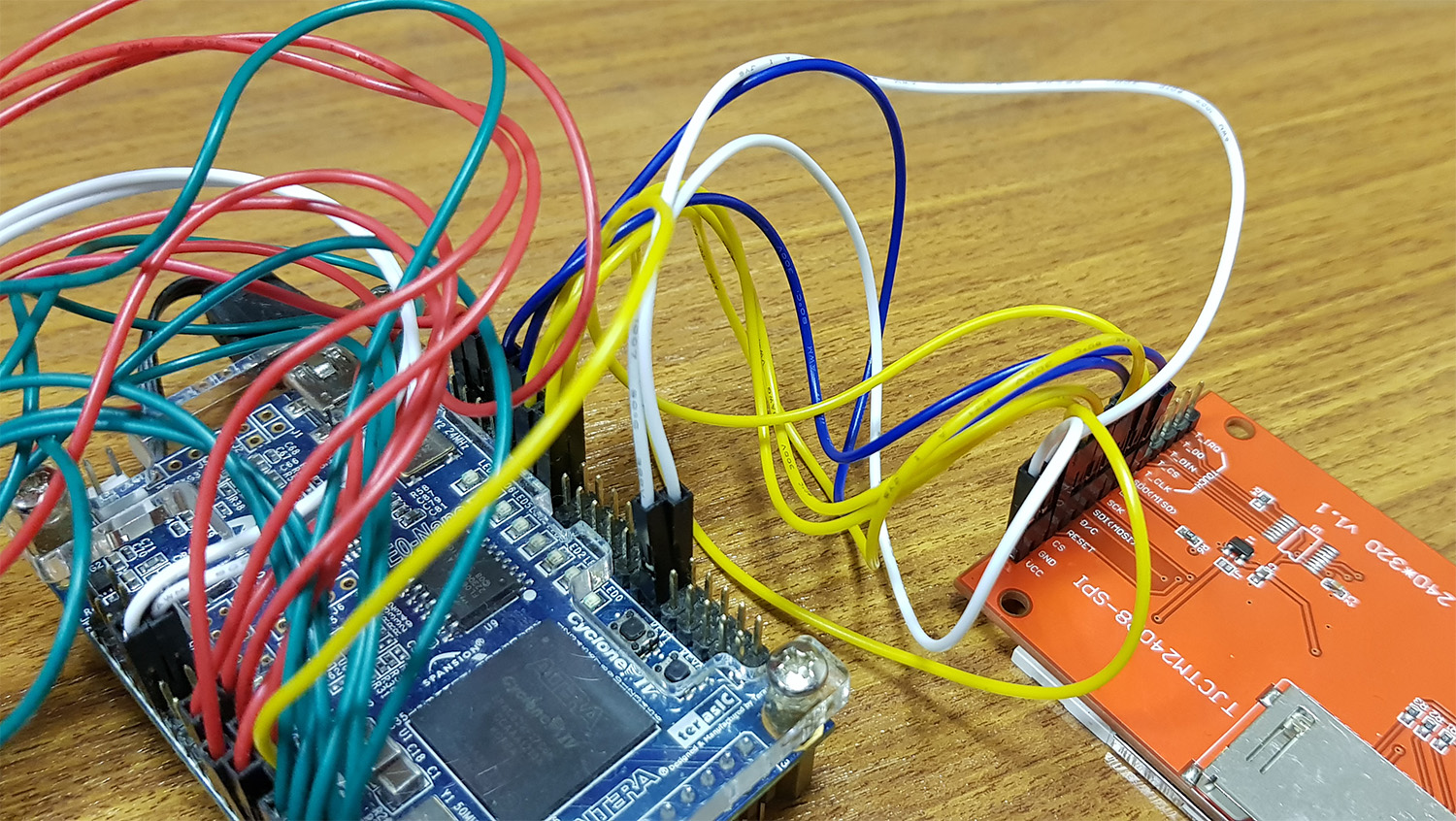
On your foto I see 8 pins for LCD connection, but SPI interface requires only one (for data transfer): Also some of your wires connected to SD-card pins, which is not used in current project. |
|
I tried to find the datasheet of that one, but it seems that it's from
China and no documents about it.
I have another SPI OLED LCD here, can you see how to plug it with your
module?
[image: OLED128_pins.png]
https://core-electronics.com.au/freetronics-128x128-pixel-oled-module.html
Btw, is the configuration on your picture is correct? As I see the diagram
both connectors are nearly identical and parallel, but your real picture is
different.


…On Tue, 8 Jan 2019 at 19:47, ZFTurbo ***@***.***> wrote:
On your foto I see 8 pins for LCD connection, but SPI interface requires
only one:
https://en.wikipedia.org/wiki/Serial_Peripheral_Interface
Also some of your wires connected to SD-card pins, which is not used in
current project.
—
You are receiving this because you authored the thread.
Reply to this email directly, view it on GitHub
<#3 (comment)>,
or mute the thread
<https://github.com/notifications/unsubscribe-auth/AEuStEj4v3B-Txv5Gt7JMiF-luviKBECks5vBGIugaJpZM4Zy27n>
.
--
Đoàn Gia Bảo
Tel: 01268.189.260
|
|
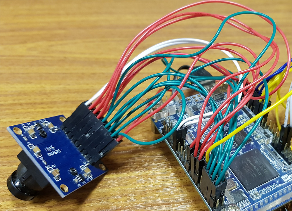
Btw, I didn't see the pins XCLK, PCLK from Camero connected to any where in the diagram?
|

|
I will be able to check device connections at Monday. I will post if diagram is totally correct then. |
|
We checked connections today. It must be like that: We updated picture in project. I also made 2 fotos. Connection scheme can be restored from them: |
Hi,
I tried to buy the same components as your spec, but it seems that there are some slight differnce and after 100% sucessful build, it didn't work at all.
Can you help to guide me how to configure with my components here, as I try to plug in as far as I know but the LCD is not working and didn't show anything.
The text was updated successfully, but these errors were encountered: