The Cordwood Puzzle evokes an era of stuffing massive components into small spaces without a clear idea of where this is all heading! Introducing the Boldport Club Project #3.


A feature of this kit is that "all the comprehensive assembly guides were mysteriously missing". i.e. yes, it is a puzzle! If you don't want spoilers, do not read any further;-)


Parts count? All in order, of course. It is unusual and fascinating to see these jumbo parts - 2W resistors and 10mm LEDs. Pretty rare these days, so fun to play with.
| Ref | Item | Qty |
|---|---|---|
| - | identical PCBs (96.6x16.6 mm each) | 2 |
| LED1,LED4 | green 10mm LEDs 1142474 | 2 |
| LED2,LED5 | yellow 10mm LEDs 1168543 | 2 |
| LED3,LED6 | red 10mm LEDs 1168543 | 2 |
| Q1-6 | nMOS FET, Fairchild, 2N7000 | 6 |
| - | 2-pin SMD 2.54mm pitch header | 1 |
| JP1 | 6-pin SMD 2.54mm pitch header | 1 |
| R1-3,R7-9 | 150Ω 2W resistors, 9338101 | 6 |
| R7-9,R10-12 | 10KΩ 2W resistors, 1602193 | 6 |
| C1 | 1uF capacitor, 1549977 | 1 |
| - | 24.5 mm M3 standoffs | 2 |
| - | 8mm long M3 screws | 4 |
| - | 0.84 mm diameter wire | enough |


The LEDs are rated for 20 mA with forward voltage of 2V. Therefore, with the current-limiting resistor of 150Ω, the maximum supply voltage is 5V.
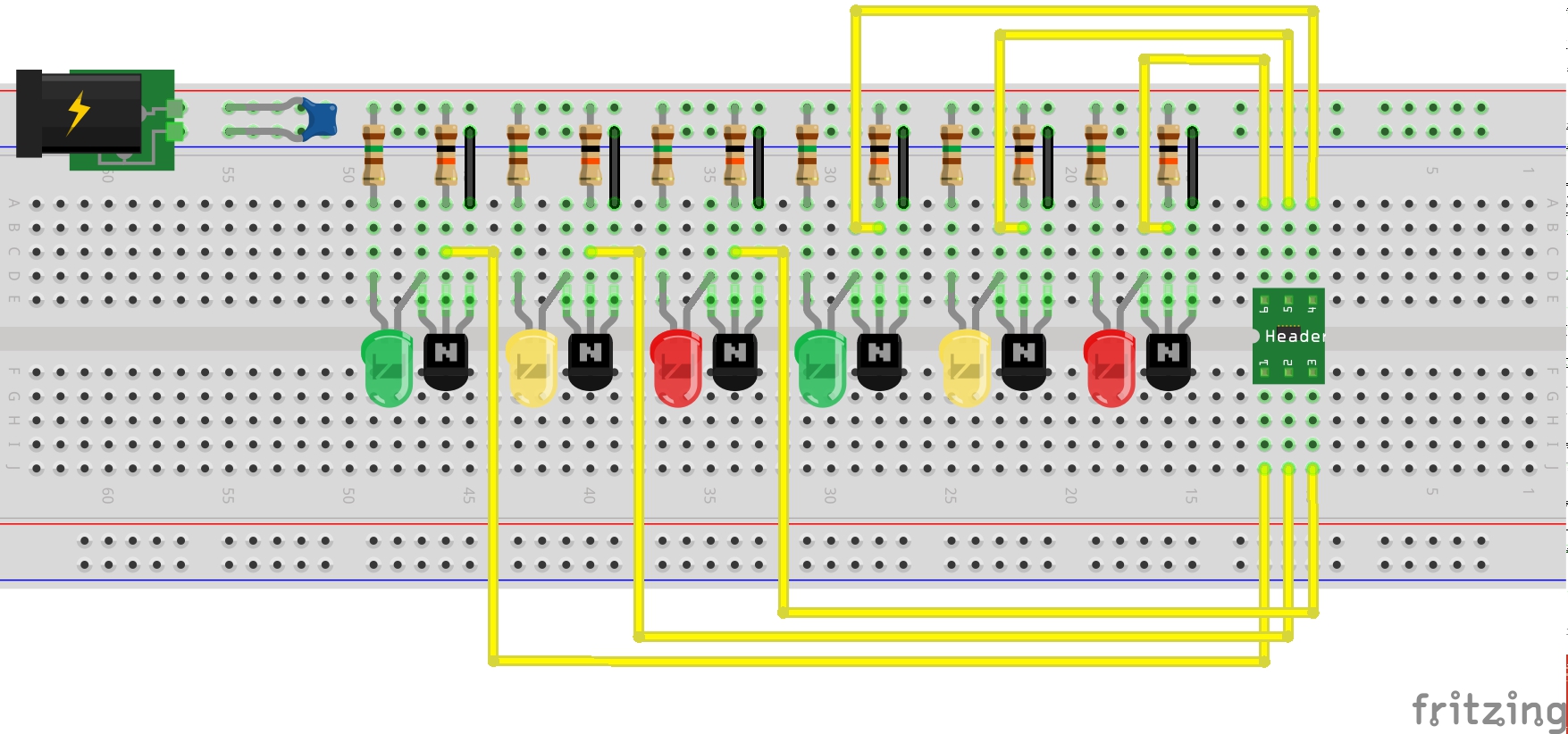
The circuit is nice and basic - a 6x array of low-side n-channel FET controlled LEDs. the gates of the MOSFETs are pulled high, so by default all the LEDs are ON. Input lines to the MOSFET gates are exposed individually (the 6-pin header), so an external source can pull the lines low and turn off the corresponding LED.
What is really neat is how this in configured in identical PCBs set parallel to each other. The true test of the "mirrored PCB" design is how many fixups are required .. and the Cordwood is as perfect an example as you will ever find, since the only asymmetry required is the single crossing of the power lines between the two boards.

- cordwood - in the Boldport shop
- cordwood - project page
- cordwood - OSH files on GitHub
- cordwood - club community site, packed with resources for the project
- 2N7000 datasheet
- LEAP#321 cordwood-too - the next project in the series
- ..as mentioned on my blog