Testing a basic Colpitts Oscillator circuit
A Colpitts oscillator uses a combination of inductors (L) and capacitors (C) to produce an oscillation at the resonant frequency of LC circuit.
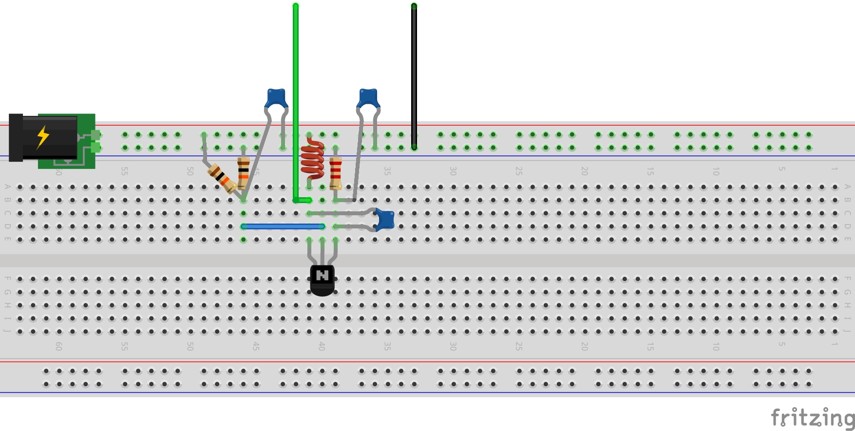
The distinguishing feature of a Colpitts oscillator is that the feedback to gain device (here an NPN BJT) is taken from the midpoint of the two capacitors.
With C1,C2=100nF and L1=1mH, I should expect oscillation at 22.5kHz, however on my first breadboard build I'm getting around 33kHz:

So more experiments required..
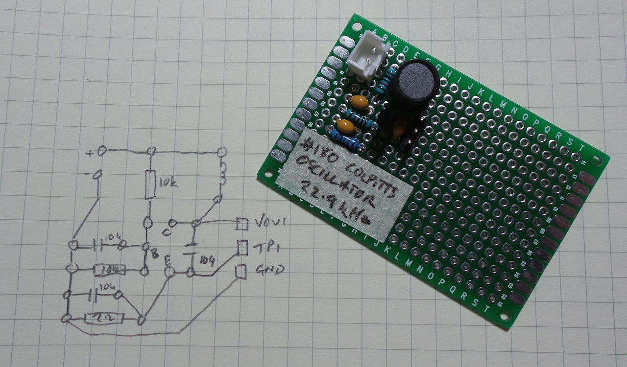
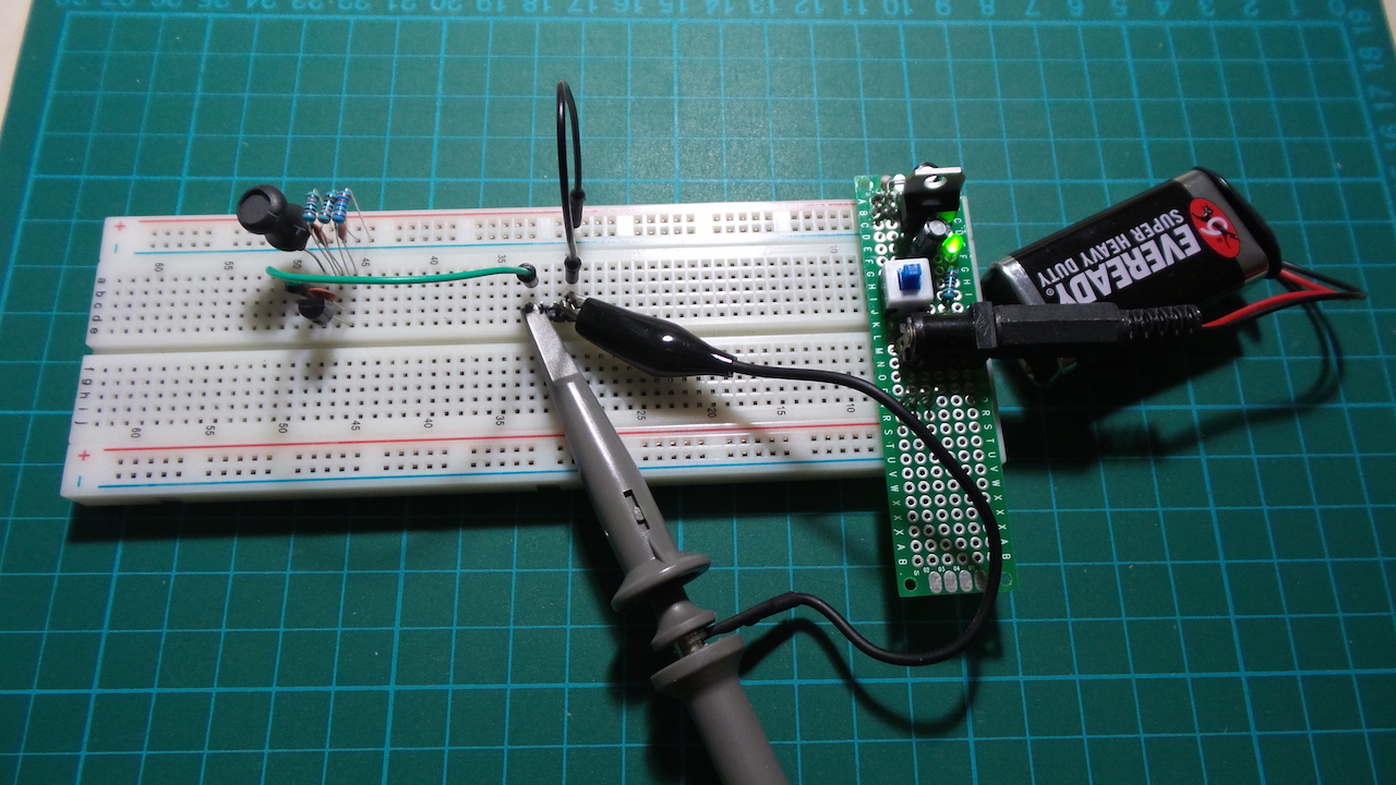
Putting the circuit on a protoboard and using some better quality capacitors makes all the difference!
I'm seeing an almost perfect 22.9kHz compared to the theoretical 22.5kHz.
The frequency can be tuned (reduced) with a capacitor in parallel with the inductor, up to about 100nF when the oscillation will be lost.
Here's an AC plot showing Vout on CH1, and TP1 on CH2. Some things to note:
- there's some distortion at the lower end of the Vout cycle; I tried twaeking the transistor bias to eliminate this but to no effect
- an almost perfect sine at TP1 (midpoint of the capacitor bridge/transistor emitter)
- 4.2V swing on Vout - not bad for a 5v supply
- 2V swing on TP1
Here's the DC-coupled plot, with both channels shifted down -5V
- Vout is oscillating around 5V
- TP1 oscillates ~2.8V

- Colpitts Oscillator - wikipedia
- The Colpitts Oscillator - ElectronicsTutorials
- More Oscillators - TE
- ..as mentioned on my blog