Test a CMOS frequency counter circuit with a 100Hz - 5MHz range
I found this circuit published in Electronics magazine (Sep 16 1976).
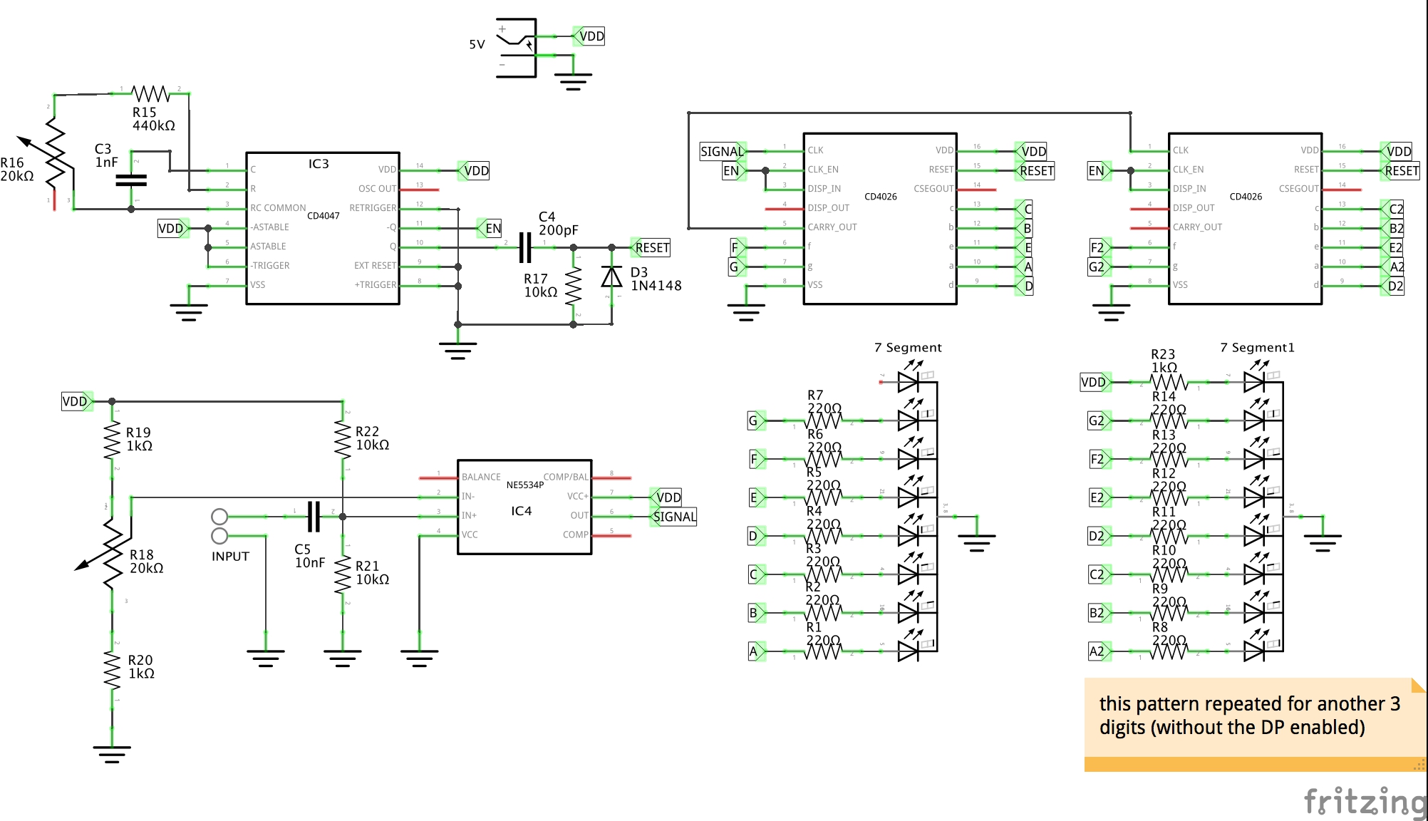
It's a classic demonstration of the CD4026 "bucket-brigade" and CD4047 astable oscillator.
The frequency counter is governed by a CD4047 oscillator. Since this offers a clean 50% duty cycle, it is ideal for flipping the circuit between two modes:
- sampling period
- display period
The frequency is tuned with 10nF and a resistor network comprising 2 x 220kΩ and a 20kΩ pot. Thus the frequency limits are expected to be between about 49Hz and 51Hz.
At 50Hz, the cycle time is 20ms. At 50% duty cycle, that's 10ms for sampling and 10ms for display.
So given the frequency count displayed is based on a 10ms sample, the reading is therefore in tenths of a kHz. The decimal point is enabled on the second digit in the display so the result may be easily read as kHz.
Here are some traces of the trigger signal:
- CH1: oscillator output Q COMPLEMENT
- CH2: reset trigger signal

Close-up on the trigger signal:
The counter is based on the classic CD4026 "bucket-brigade" configuration
A signal may be directly fed into the CD4026 chain. That works fine as long as the signal is suitable.
With a 2V p-p sine wave directly connected with a 10nF decoupling capacitor, the counter works up to 3MHz or so.
To get a little more headroom, I was able to extend the frequency range to just over 5MHz with a NE5534P op amp configured as an adjustable comparator.
At 5kHz, the NE5534P op amp procudes a clear square wave input to the counter.
- CH1: input signal
- CH2: non-inverting input
- CH3: op amp output/input to counter

At 5MHz, the NE5534P op amp output is quite distorted, however it is still good enough to drive the counter.
- CH1: input signal
- CH2: non-inverting input
- CH3: op amp output/input to counter


- Frequency Counter Design - Lloyd F. Botway, Electronics Sep 16 1976
- CD4026 Datasheet
- CD4047 datasheet
- NE5534P datasheet
- ..as mentioned on my blog