A small collection of Python scripts for semi-automatic mapping of RGB pixels in 3D space using computer vision. Designed particularly for mapping out trees that have been wrapped with pixels.
Final output is an xLights file format 3D model of the pixels.
Example of a pixel-wrapped tree and the resulting 3D model in xLights:

Some poorly shot video of the tree in action on Halloween during trick or treating:
https://www.youtube.com/watch?v=ifu_yMDDcYU
And red white & blue on election night:
https://www.youtube.com/watch?v=PFOB23FCTPQ
- opencv-python
- Lumos library to control pixels via E1.31 sACN
- Use this fork for Python 3 compatibility
- numpy
- imutils
- scikit-image
- playsound
- matplotlib
- Locate camera positions - equilateral triangle around pixel array
- For each camera location:
- Level & align camera
- Capture data using computer vision with manual assist
- After data from all three cameras is captured:
- Combine three 2D data files into one xLights 3D model file
The three camera locations must be exactly 120 degrees apart around the object to be mapped (in my case, a tree), forming the three vertices of an equilateral triangle. The camera should be as close to the object/tree as possible while still fully capturing the entire object within the field of view.
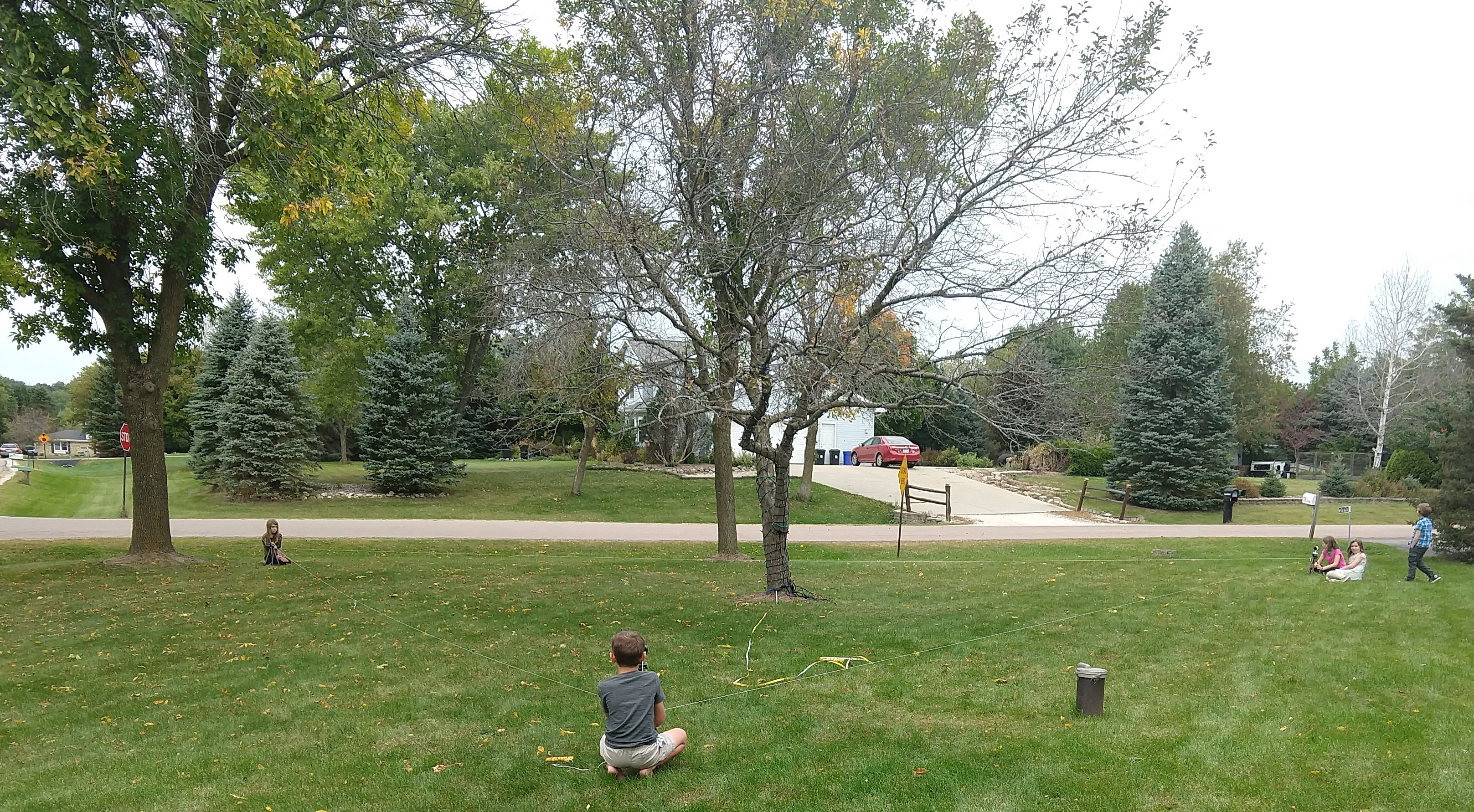
Once the required distance from the object has been determined (based on its size and the camera FOV) by moving the camera around and viewing the image, the length of the edges of the equilateral triangle can be determined. Once these lengths are known, a simple alignment method is to cut three strings to the same length of the triangle edge and pull them tight into the shape of the triangle. Mark the locations of the three vertices on the ground with spray paint. These are the three camera locations that will be used in the following steps.
Getting some help from the kids holding strings in place:
For correct results when translating the three sets of 2D pixel coordinates into one set of 3D coordinates, the camera must be aligned to point directly at the center of the equilateral triangle from each of its three capture locations. Additionally, the height of the camera at each location must be the same relative to a fixed reference point (not relative to ground, unless the ground is perfectly flat).
Using a camera tripod is highly recommended, as tripods have adjustments to move the camera in each of the required axis and usually have bubble levels built in to aid in leveling.
Once the camera has been placed directly over its required position on the tripod, the first step is to get the camera leveled. Once it has been leveled, the camera_align.py script can be run to aid in rotational and vertical alignment. You'll need to edit the first two lines of code in camera_align.py to specify the resolution of your camera and its VideoCapture source address (an IP address for a WiFi camera or simply an index for a USB camera).
First, place some easily visible objects (5 gallon bucket, for example) at the other two camera locations on the equilateral triangle. The camera on the tripod needs to be aimed so that its center point is directly between the objects.
camera_align.py will overlay two yellow vertical lines on the camera image. The location of these lines can be moved in and out by using the right and left arrow keys on the keyboard. When properly aligned, these yellow lines should pass directly over the two objects (buckets or whatever) that you've placed at the two other camera locations.
Note that you'll likely need to re-level the camera as you make rotational adjustments. It doesn't take much movement to bump things out of level.
Video showing horizontal alignment process using soccer balls as markers

Once the camera is properly aligned horizontally, the last step is to set its vertical location relative to a fixed object that's visible from all three camera locations. In my case I manually turned on a single pixel on the tree that I was mapping using the Display Testing function in Falcon Player - FPP. This pixel was used as my vertical reference point for all three camera locations. I then raised or lowered the camera on the tripod using the hand crank extension until the horizontal blue overlay line from camer_align.py was directly over the reference pixel. As before, frequently recheck that the camera remains level in all directions while doing the vertical alignment.
pixel_automap.py is used to capture the data. This script will be run three times, once with the camera at each of the three locations identified above.
Depending on your controller configuration, you may need to put it into Bridge Mode to allow it to receive sACN packets from pixel_automap.py.
There are a number of configuration elements at the beginning of the script that will need to be modified to fit your setup. First, the E1.31 sACN Universes need to be configured. This will be entirely dependent on the number of pixels you're mapping and how you have the Universes set up in your pixel controller. You'll also need to specify the camera source to use. You can also optionally specify an output RGB value to use (default is [100,100,100]) when the pixels are turned on and the name of the output CSV file that is created.
Once pixel_automap.py is configured and run, it will first turn on all of the pixels that have been configured for E1.31 sACN control and show the camera image. The user can then click points around the pixels to create a polygon that encompasses all of the pixels. This polygon will be used as a mask when detecting individual pixels. Bright lights outside of this polygon will be ignored during the detection process. Left click to create new points on the polygon and right click to end the polygon.
Video showing polygon drawing process

After the polygon has been drawn, pixel_automap.py will turn on each individual pixel one at a time and try to detect its location. If the script is able to detect the location, it will draw a red circle around the pixel, record the coordinates in the output CSV file, and automatically move to the next pixel. If it us unable to detect the location of the pixel, it will play a sound on the computer to get your attention. At this point you have two choices about how to proceed:
- If you are able to see the location of the pixel, you may click on it. The coordinates of your click will be used as the pixel location.
- If you are unable to see the location of the pixel (it's on the back side of the tree, for example), simply click anywhere outside the masking polygon. The coordinates of the pixel will be stored as [0,0] in the output CSV file.
Video showing pixel detection process

Once a CSV file has been created for each of the three camera positions, those three CSV files are used by calc_points.py to convert the 2D coordinates captured from each location into a single set of 3D coordinates.
At the top of the script are several parameters that must be edited:
- files - A list of the three CSV data files containing 2D coordinates to combine
- fov - Field of view of the camera [degreesHorizontal,degreesVertical]
- res - Resolution (in pixels) of the camera [Horizontal, Vertical]
- xLights_output_scale_factor - A scaling factor to reduce the size of the xLights output file to a reasonable size
- outfilename - File name of the final xLights model file
Strictly speaking, only two camera locations are needed to generate 3D coordinates. However, because many pixels will be blocked from a single camera location (the tree is not transparent), three positions are used.
Because there are three camera locations, there are three different combinations of two camera positions that can each be used to generate a set of 3D coordinates (positions 1&2,2&3,3&1). calc_points.py will calculate a set of 3D coordinates from each 2-camera combination, and then average the three sets of 3D coordinates together to generate the final result.
Three sets of 3D coordinates prior to averaging:

Combined/averaged coordinate set along with final xLights model:

Once the final set of 3D coordinates has been generated, calc_points.py will then export the final results to an xLights format model file and plot the results for viewing.
