This repository presents the Design and implementation of mixed signal circuit of MOD-10-Ripple-Counter. Design of MOD-10-Ripple-Counter is done by using an Opensource EDA Tool called eSim, an Opensource Spice Simulator called ngspice. Verilog code is designed in opensource Verilog Environment called Makerchip.
1.ABSTRACT
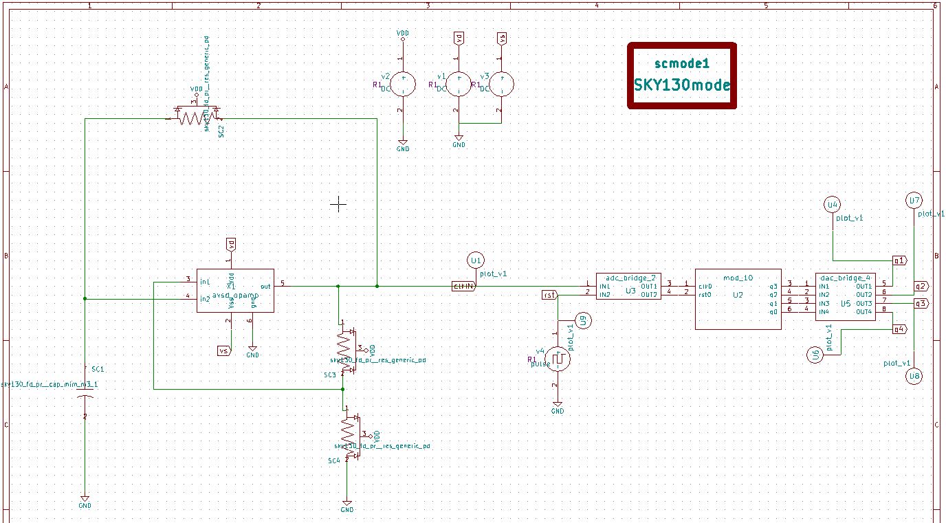
A Mod-10(decade) counter is a sequential circuit which counts from 0(0000) to 9(1001) after 9th pulse i.e.; on the 10th pulse it is resets to 0. Input to the decade counter is given through Op-amp Multivibrator which generates clock pulse to the counter.
eSim is an open source EDA tool for circuit design, simulation and analysis , developed by FOSSEE Team at IIT Bombay. It is an integrated tool build using open source softwares such as KiCad, Ngspice and GHDL. More details on eSIM tool can be found here
Makerchip is an opensource tool for developing verilog code for the digital circuits and simulate it. By using using eSim and makerchip we can develop model for our selected digital circuit. More details on Makerchip can be found here
It is a tool which converts Verilog code to C++ objects. More details on verilator can be found here
The Op-amp Multivibrator is an astable oscillator circuit that generates a square wave using an RC timing network connected to the inverting input of the operational amplifier and a voltage divider network connected to the other non-inverting input. It has two states, neither of which are stable as it is constantly switching between these two states with the time spent in each state controlled by the charging or discharging of the capacitor through a resistor. The Time period of the square wave is given by: T = 2RC ln(1 + β / 1 - β ) Where, β = R2/R1+R2
MOD-10 counter also called as Decade counter has 10 states, it counts sequence from zero (0000) to decimal nine (1001). A decade counter is also often used for dividing a pulse frequency exactly by 10. The input pulses are applied to the paralleled clock inputs, and the output pulses are taken from the output of flip-flop, which has one-tenth the frequency of the input signal. In the proposed work, we are going to design digital blocks with the Verilog behavioural design of the JK flip-flop and NAND gate that is used as a basic block for the decade counter. To use these digital blocks we are going to interface digital to analog and analog to digital converters.


\TLV_version 1d: tl-x.org
\SV
/* verilator lint_off UNUSED*/  /* verilator lint_off DECLFILENAME*/  /* verilator lint_off BLKSEQ*/  /* verilator lint_off WIDTH*/  /* verilator lint_off SELRANGE*/  /* verilator lint_off PINCONNECTEMPTY*/  /* verilator lint_off DEFPARAM*/  /* verilator lint_off IMPLICIT*/  /* verilator lint_off COMBDLY*/  /* verilator lint_off SYNCASYNCNET*/  /* verilator lint_off UNOPTFLAT */  /* verilator lint_off UNSIGNED*/  /* verilator lint_off CASEINCOMPLETE*/  /* verilator lint_off UNDRIVEN*/  /* verilator lint_off VARHIDDEN*/  /* verilator lint_off CASEX*/  /* verilator lint_off CASEOVERLAP*/  /* verilator lint_off PINMISSING*/  /* verilator lint_off LATCH*/  /* verilator lint_off BLKANDNBLK*/  /* verilator lint_off MULTIDRIVEN*/  /* verilator lint_off NULLPORT*/  /* verilator lint_off EOFNEWLINE*/  /* verilator lint_off WIDTHCONCAT*/  /* verilator lint_off ASSIGNDLY*/  /* verilator lint_off MODDUP*/  /* verilator lint_off STMTDLY*/  /* verilator lint_off LITENDIAN*/  /* verilator lint_off INITIALDLY*/  /* verilator lint_off */

//Your Verilog/System Verilog Code Starts Here:
module mod_10(clk,q,rst);
input clk,rst;
output [3:0]q;
reg [3:0]q=4'b0;
reg [4:0]a=5'd0;
always@(posedge clk)
begin
if(rst)
q<=0;
else
begin
a = a+1;
if(a<=9)
q<=q+1;
else
begin
a=0;
q<=0;
end
end
end
endmodule


//Top Module Code Starts here:
	module top(input logic clk, input logic reset, input logic [31:0] cyc_cnt, output logic passed, output logic failed);
		logic  rst;//input
		logic  [3:0] q;//output
//The $random() can be replaced if user wants to assign values
		assign rst = $random();
		mod_10 mod_10(.clk(clk), .rst(rst), .q(q));

\TLV
//Add \TLV here if desired
\SV
endmodule


* c:\users\dell\esim-workspace\mod-10_ripple\mod-10_ripple.cir

.include avsd_opamp.sub
.include "C:\FOSSEE\eSim\library\sky130_fd_pr\models\sky130_fd_pr__model__diode_pw2nd_11v0.model.spice"
.include "C:\FOSSEE\eSim\library\sky130_fd_pr\models\sky130_fd_pr__model__inductors.model.spice"
.include "C:\FOSSEE\eSim\library\sky130_fd_pr\models\sky130_fd_pr__model__diode_pd2nw_11v0.model.spice"
.include "C:\FOSSEE\eSim\library\sky130_fd_pr\models\sky130_fd_pr__model__linear.model.spice"
.lib "C:\FOSSEE\eSim\library\sky130_fd_pr\models\sky130.lib.spice" tt
.include "C:\FOSSEE\eSim\library\sky130_fd_pr\models\sky130_fd_pr__model__r+c.model.spice"
.include "C:\FOSSEE\eSim\library\sky130_fd_pr\models\sky130_fd_pr__model__pnp.model.spice"
* s c m o d e
* u3  clkin rst net-_u2-pad1_ net-_u2-pad2_ adc_bridge_2
v4  rst gnd pulse(5 0 0 0 0 8m 10m)
* u2  net-_u2-pad1_ net-_u2-pad2_ net-_u2-pad3_ net-_u2-pad4_ net-_u2-pad5_ net-_u2-pad6_ mod_10
* u5  net-_u2-pad3_ net-_u2-pad4_ net-_u2-pad5_ net-_u2-pad6_ q1 q2 q3 q4 dac_bridge_4
* u4  q1 plot_v1
* u7  q2 plot_v1
* u8  q3 plot_v1
* u6  q4 plot_v1
* u9  rst plot_v1
x1 vd vs net-_sc3-pad2_ net-_sc1-pad1_ clkin gnd avsd_opamp
xsc2 net-_sc1-pad1_ clkin vdd sky130_fd_pr__res_generic_pd L=24.1
xsc3 clkin net-_sc3-pad2_ vdd sky130_fd_pr__res_generic_pd L=52
xsc4 net-_sc3-pad2_ gnd vdd sky130_fd_pr__res_generic_pd L=52
xsc1 net-_sc1-pad1_ gnd sky130_fd_pr__cap_mim_m3_1 W=10000 L=1 MF=1
v1 vd gnd  dc 5
* u1  clkin plot_v1
v2 vdd gnd  dc 5
v3 vs gnd  dc -5
a1 [clkin rst ] [net-_u2-pad1_ net-_u2-pad2_ ] u3
a2 [net-_u2-pad1_ ] [net-_u2-pad2_ ] [net-_u2-pad3_ net-_u2-pad4_ net-_u2-pad5_ net-_u2-pad6_ ] u2
a3 [net-_u2-pad3_ net-_u2-pad4_ net-_u2-pad5_ net-_u2-pad6_ ] [q1 q2 q3 q4 ] u5
* Schematic Name:                             adc_bridge_2, NgSpice Name: adc_bridge
.model u3 adc_bridge(in_low=1.0 in_high=2.0 rise_delay=1.0e-9 fall_delay=1.0e-9 )
* Schematic Name:                             mod_10, NgSpice Name: mod_10
.model u2 mod_10(rise_delay=1.0e-9 fall_delay=1.0e-9 input_load=1.0e-12 instance_id=1 )
* Schematic Name:                             dac_bridge_4, NgSpice Name: dac_bridge
.model u5 dac_bridge(out_low=0.0 out_high=5.0 out_undef=0.5 input_load=1.0e-12 t_rise=1.0e-9 t_fall=1.0e-9 )
.tran 1.5e-03 100e-03 0e-03

* Control Statements
.control
run
print allv > plot_data_v.txt
print alli > plot_data_i.txt
plot v(q0)
plot v(q1)
plot v(q2)
plot v(q3)
plot v(rst)
plot v(clk)
plot v(clk) v(rst)+5  v(q3)+10 v(q2)+18 v(q1)+27 v(q0)+35
.endc
.end

- Open eSim
- Run NgVeri-Makerchip
- Add top level verilog file in Makerchip Tab
- click on Edit in makerchip to simulate the verilog code
- Click on NgVeri tab
- Add dependency files(If any)
- Click on Run Verilog to NgSpice Converter
- Debug if any errors
- Model created successfully
- Open new terminal
- Clone this project using the following command:
git clone https://github.com/abhinandann/mod-10_ripple.git
- Change Directory:
cd esim-workspace/mod-10_ripple
- Run Ngspice:
ngspice mod-10_ripple.cir.out
- To run the project in eSim:
- Run eSim
- Load the project
- Open eeSchema
- https://www.electronics-tutorials.ws/counter/mod-counters.html
- https://www.tutorialspoint.com/linear_integrated_circuits_applications/linear_integrated_circuits_applications_waveform_generators.html
- FOSSEE, IIT Bombay
- Steve Hoover, Founder, Redwood EDA
- Kunal Ghosh, Co-founder of VLSI System Design (VSD) Corp. Pvt. Ltd.
- Sumanto kar, Sr.Project Technical Assistant, IIT BOMBAY
ABHINANDAN R APPANNAVAR, 7th SEM B.E(ECE), SDM COLLEGE OF ENGINEERING AND TECHNOLOGY,DHARWAD-580002
- Contact: abhinandan7353@gmail.com