Add preliminary SPI support for BeagleBone Black #46
Conversation
This file contains bidirectional Unicode text that may be interpreted or compiled differently than what appears below. To review, open the file in an editor that reveals hidden Unicode characters.
Learn more about bidirectional Unicode characters
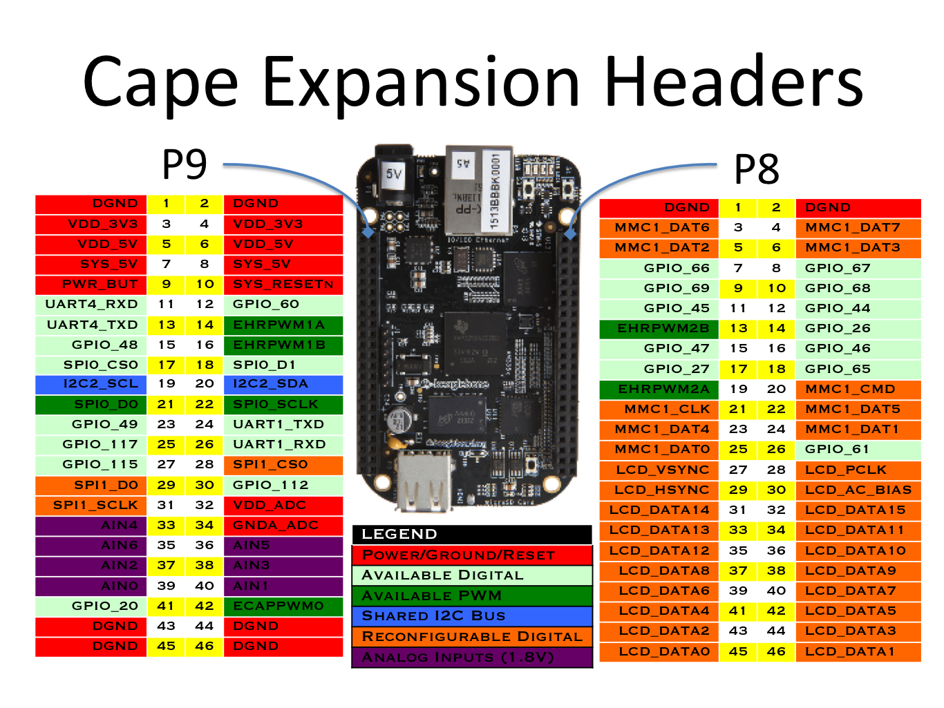
Refer to header default pin modes
http://beagleboard.org/static/images/cape-headers.png

P9_17 (SPI0_CSO => CE0) enables peripheral device
P9_18 (SPI0_D1 => MOSI) outputs data to peripheral device
P9_21 (SPIO_DO => MISO) receives data from peripheral device
P9_22 (SPI0_SCLK => SCLK) outputs clock signal

Use config-pin to set pin mode for SPI pins
https://github.com/beagleboard/bb.org-overlays/tree/master/tools/beaglebone-universal-io

config-pin p9.17 spi_cs
config-pin p9.18 spi
config-pin p9.21 spi
config-pin p9.22 spi_sclk
reuse the Raspberry Pi SPI class as both are
Linux boards using spidev.  The main difference
is the pins numbers are different.

Testing with Adafruit_CircuitPython_BME280 in SPI mode.

TODO: wire up the board to the BeagleBone Black

Current output:

debian@beaglebone:~/Adafruit_CircuitPython_BME280$ sudo python3 examples/bme280_simpletest.py
SPI(): __init()
SPI(): beaglebone_black: from adafruit_blinka.microcontroller.raspi_23.spi import SPI as _SPI
spiPorts: ((0, P9_22, P9_18, P9_21), (1, P9_22, P9_18, P9_21))
for:
0 P9_22 P9_18 P9_21
Line 91
<class 'adafruit_blinka.microcontroller.raspi_23.spi.SPI'>
<adafruit_blinka.microcontroller.raspi_23.spi.SPI object at 0xb6b3c890>
Traceback (most recent call last):
  File "examples/bme280_simpletest.py", line 15, in <module>
    bme280 = adafruit_bme280.Adafruit_BME280_SPI(spi, bme_cs)
  File "/usr/local/lib/python3.5/dist-packages/adafruit_circuitpython_bme280-2.1.1.dev3+g1416d93-py3.5.egg/adafruit_bme280.py", line 247, in __init__
  File "/usr/local/lib/python3.5/dist-packages/adafruit_circuitpython_bme280-2.1.1.dev3+g1416d93-py3.5.egg/adafruit_bme280.py", line 78, in __init__
RuntimeError: Failed to find BME280! Chip ID 0x0
|
I have wired up the BME280 per the learning guide. The BME280 CircuitPython example runs OK on the BeagleBone: |
|
Testing with SP1 port instead of SPI0 Refer to: SPI1 conflicts with HDMI Audio (McASP) Refer to: To Disable HDMI AUDIO, uncomment this line in /boot/uEnv.txt: Set pin modes for SPI1 with: BME280 wiring: +++ b/examples/bme280_simpletest.py
@@ -3,15 +3,17 @@ import time
import board
import busio
import adafruit_bme280
+import digitalio
# Create library object using our Bus I2C port
-i2c = busio.I2C(board.SCL, board.SDA)
-bme280 = adafruit_bme280.Adafruit_BME280_I2C(i2c)
+#i2c = busio.I2C(board.SCL, board.SDA)
+#bme280 = adafruit_bme280.Adafruit_BME280_I2C(i2c)
# OR create library object using our Bus SPI port
#spi = busio.SPI(board.SCK, board.MOSI, board.MISO)
-#bme_cs = digitalio.DigitalInOut(board.D10)
-#bme280 = adafruit_bme280.Adafruit_BME280_SPI(spi, bme_cs)
+spi = busio.SPI(board.SCK_1, board.MOSI_1, board.MISO_1)
+bme_cs = digitalio.DigitalInOut(board.CE1)
+bme280 = adafruit_bme280.Adafruit_BME280_SPI(spi, bme_cs)
# change this to match the location's pressure (hPa) at sea level
bme280.sea_level_pressure = 1013.25BME280 on SPI1 works OK |
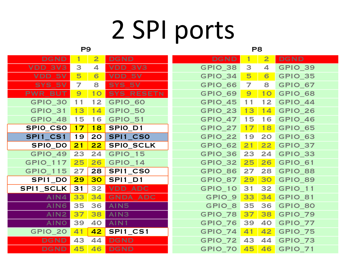
Refer to:
http://beagleboard.org/static/images/cape-headers-spi.png

CE1 P9.28 SPI1_CS0
MISO_1 P9.29 SPI1_D0
MOSI_1 P9.30 SPI1_D1
SCLK_1 P9.31 SPI_SCLK

SPI1 conflicts with HDMI Audio (McASP)

Refer to:
https://elinux.org/Beagleboard:BeagleBoneBlack_Debian#U-Boot_Overlays

To Disable HDMI AUDIO, uncomment this line in /boot/uEnv.txt:
disable_uboot_overlay_audio=1

Set pin modes for SPI1 with:

config-pin p9.28 spi_cs
config-pin p9.29 spi
config-pin p9.30 spi
config-pin p9.31 spi_sclk
|
@ladyada I have tested OK with both SPI0 and SPI1 on the BeagleBone Black with the BME280 sensor |
|
rad! ok wanna do a merge and release then? |
|
@ladyada |
Sign up for free
to join this conversation on GitHub.
Already have an account?
Sign in to comment
Add this suggestion to a batch that can be applied as a single commit.
This suggestion is invalid because no changes were made to the code.
Suggestions cannot be applied while the pull request is closed.
Suggestions cannot be applied while viewing a subset of changes.
Only one suggestion per line can be applied in a batch.
Add this suggestion to a batch that can be applied as a single commit.
Applying suggestions on deleted lines is not supported.
You must change the existing code in this line in order to create a valid suggestion.
Outdated suggestions cannot be applied.
This suggestion has been applied or marked resolved.
Suggestions cannot be applied from pending reviews.
Suggestions cannot be applied on multi-line comments.
Suggestions cannot be applied while the pull request is queued to merge.
Suggestion cannot be applied right now. Please check back later.
FYI - THIS IS WORK IN PROGRESS. ADDITIONAL COMMITS WILL BE ADDED TO THIS PR.
Refer to header default pin modes
http://beagleboard.org/static/images/cape-headers.png
P9_17 (SPI0_CSO => CE0) enables peripheral device
P9_18 (SPI0_D1 => MOSI) outputs data to peripheral device
P9_21 (SPIO_DO => MISO) receives data from peripheral device
P9_22 (SPI0_SCLK => SCLK) outputs clock signal
Use config-pin to set pin mode for SPI pins
https://github.com/beagleboard/bb.org-overlays/tree/master/tools/beaglebone-universal-io
config-pin p9.17 spi_cs
config-pin p9.18 spi
config-pin p9.21 spi
config-pin p9.22 spi_sclk