This project is no longer under active development.
This project is just a place for me to record any progress I make as I attempt to build a replica of the BB-8 droid from the new Star Wars: The Force Awakens movie.
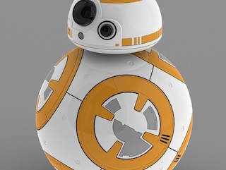
Above image from Star Wars The Force Awakens - BB-8 Ball Droid by lilykill - Published on November 30, 2014
- This BB-8 replica git repository is created by a Star Wars fan for other such fans. It is not sponsored or endorsed by Lucasfilm Ltd.
- Star Wars, its characters, costumes, and all associated items are the intellectual property of Lucasfilm. © & ™ Lucasfilm Ltd. All rights reserved.
- Some of the control mechanisms in this BB-8 replica are covered by patents granted and/or pending to Sphero.
Video of BB-8 on stage at Star Wars Celebration 2015
Interview with the creators of the BB-8 props used in The Force Awakens
Buy your own Sphero BB-8 Toy Here!
My Sphero 1 Hacking
My Sphero 1 Teardown
My Sphero 2 Teardown
Astromech.net - The Official Website of the R2-D2 Builders Club
Make This Mini Star Wars BB-8 Ball Droid with a Hacked Sphero by Christian Poulsen
UBREAKIFIX teardown of Sphero BB-8 toy
BB-8 Construction Conversation on Hackaday
How to Clone this GitHub Repository
Control Guru PID Notes
Brett Beauregard's PID Notes
Brett Beauregard's Relay Method Tuning Notes
Neil Kolban's ESP8266 Documentation
JEELABS' esp-Link firmware
InvenSense MPU-9150 9-axis Motion Processing Unit Register Map & Description
It's been awhile since I logged anything here but I have been making some good progress on building my 10" BB-8 prototype. The latest plan for my BB-8 replica no longer follows the Sphero model but those of ball bots like this one that I used to see local robot builders making 15 years ago. I currently have a platform built out of foam board spinning around inside of a hamster ball. It only contains one motor at this point in time and that motor is used to change the pitch of the platform. Pitching the platform allows moving the mass hanging below the platform so that it is forward or behind the axle connecting the platform to the sphere. This allows for the bot's motion to be controlled in the forward / reverse direction. Once I am happy with my control scheme for this axis, then I will add the ability to tilt the mass to the left and right for turning when in motion. Spinning the bot in-place is another future project.

My initial version of the bb-8 firmware used a very simple control loop for the main drive motor. The amount of stick deflection on the RC transmitter was used to control the velocity of the motor. A PI algorithm was used to close the loop between the desired velocity and the shaft encoder output. The control obtained from such a setup was very similar to what I remember seeing in the ball bot projects 15 or so years ago. There were oscillations when I stopped and it was tricky to keep the mass in the desired location and not actually spin around inside the ball faster than the ball itself.
To make the control system more stable, I wanted to pull the IMU into the control loop so that the stick deflection could be used to control the pitch of the platform (which relates to the drive torque applied). This would make it similar to a Segway. When I first started implementing this control loop in the firmware, I hit a number of issues in my code. Each time I wanted to look at debug data from a test run or upload new firmware, I had to open the ball bot up, pull out the PCB from within the platform, and then connect to my PC via USB. This was slow and I was really worried that I might break something. I had to come up with a better debugging / programming solution.
I had purchased a $7 ESP8266 WiFi board from Adafruit a few months ago in the hopes that I could use it for a wireless interface to my mbed 1768. I was now at the stage where having such a wireless interface would be awesome. I had seen mention of JEELABS' esp-Link firmware on Hackaday in the time since I had originally obtained the board and had filed it away under interesting links for this BB-8 project. The ability of this firmware to create a simple to configure and use UART to WiFi bridge looked like it was probably ideal for my needs. I have previously written a GDB compatible UART based debug monitor called MRI that works on the LPC1768. If I could bridge the debugger's UART to WiFi then I would have an ideal debug solution.
The Good: The esp-link firmware was very easy to configure and use as a transparent bridge to allow GDB to connect to a wireless TCP/IP socket from my Mac to MRI running on the LPC1768. The feature set of my MRI debug monitor is comparable to a full-blown JTAG/SWD debugger and now it works wirelessly.
The Bad: I had great difficulty getting the esp-link firmware installed on my ESP-1 board. I tried to use esptool.py on my Ubuntu VM but I always got a "Failed to connect" error message. I did find a number of mistakes that I made in my wiring as I read through the notes here but still I could never get a good connection. In the end I gave up and used the NodeMCU Flash utility recommended by others on that same Github issue thread. That worked a charm. It never gave any errors. These flashing utilities required that my PC be connected to the ESP8266 device via its UART pins. I used my mbed-LPC1768 as a USB to serial adapter with this firmware since I wanted that microcontroller connected to the ESP8266 anyway.
Once I had a wireless debugging solution in place I was wondering if it could be utilized to facilitate wireless programming as well. The MRI debug monitor doesn't support the GDB FLASHing commands since MRI itself is running in the same FLASH that we want to reprogram. I came up with a two stage solution to this problem:
- I wrote a UART based boot loader that expects to run out RAM and not FLASH.
- This boot loader can be loaded into RAM using MRI memory write commands from the GDB remote protocol.
- The boot loader runs out of the upper RAM banks on the LPC1768. The MRI debug monitor won't have any global or stack variables in this portion of RAM.
- The binary for this boot loader is <1000 bytes in length so that it doesn't take too long to load into RAM using the GDB remote protocol.
- Supports a protocol with commands for erasing all of FLASH, programming FLASH sectors in packets of <=16k data, and resetting the device.
- Automatically detects and uses the same UART as was being used by MRI previously.
- I also wrote mriprog. This program takes advantage of MRI and the UART boot loader to load new code into the FLASH.
- It first connects to MRI running on the LPC1768 device via serial port or TCP/IP socket.
- Loads the UART boot loader into the RAM of the LPC1768 device using GDB remote protocol memory write commands.
- Uses GDB remote protocol commands to start execution of the boot loader in RAM.
- Switches to talking the protocol used by the serial boot loader. It uses that protocol to erase the device, program the new contents into the FLASH, and then reset the device.
This deployWiFi bash script shows the command line I use for running the mriprog tool in my environment.
I found great documentation on how to use the esp8266 device on Neil Kolban's site. The following image of the ESP8266 ESP-1 board and its pins was taken from Kolban's Book on ESP8266.

The following table gives an overview of what I connected to each of the pins on the ESP-1 board.
| ESP-1 board pin | Connection | Notes |
|---|---|---|
| Vcc | 3.3V | Connect to LD1117-3.3V Regulator Output |
| Reset | Unconnected | I found it best to not connect |
| CH_PD | 3.3V | Required to enable device |
| TX | mbed p14 | |
| Gnd | Ground | |
| GPIO_2 | 3.3V | |
| GPIO_0 | 3.3V | Should allow to be pulled to ground for programming. |
| RX | mbed p13 |
| LD1117 Regulator Pin | Description |
|---|---|
| Left | Ground |
| Center | 3.3V Output |
| Right | Input Vcc |


Once I had a wireless debugging / programming solution in place, I was able to quickly iterate over the control code to produce a much more stable drive control system. The above animations show the prototype running with the updated control loop.
James Bruton has started working on a new BB-8 build. It is pretty cool. Check out his video here.
I needed to be able to source more current for my motors so I replaced the TB6612FNG motor driver with a VNH3SP30 motor driver. I initially hacked it in through the use of a solder-less breadboard and several hookup wires:
I used that configuration to perform some basic testing of the motor/encoder and then replaced the driver on the actual soldered protoboard so that it could standup to being inside my ball bot:

I still haven't bothered to create a schematic for my current electronics but I did update my tables of connections for the key devices on the board. What follows are those updated wiring tables:
| mbed pin | Connection | Notes |
|---|---|---|
| p1 | Gnd | Ground Bus |
| p2 | Vin - 5V | Connected to 5V BEC |
| p5 - p8 | SPI | Reserved for SD card |
| p9 | IMU SDA (3) | |
| p10 | IMU SCL (4) | |
| p11 | Left Motor - Encoder A | Yellow Wire (5) |
| p12 | Left Motor - Encoder B | White Wire (6) |
| p13 | ESP8266 RX | WiFi Debugging/Programming |
| p14 | ESP8266 TX | WiFi Debugging/Programming |
| p15 | Right Motor - Encoder A | Yellow Wire (5) |
| p16 | Right Motor - Encoder B | White Wire (6) |
| p17 | RC Channel 1 | Yaw Channel - Signal is White Wire (1) |
| p18 | RC Channel 2 | Pitch Channel - Signal is White Wire (1) |
| p19 | VNH3SP30 2INb (13) | Right Motor (Level Shift) |
| p20 | VNH3SP30 2INa (14) | Right Motor (Level Shift) |
| p21 | VNH3SP30 2PWM (12) | Right Motor (Level Shift) |
| p22 | VNH3SP30 1PWM (4) | Left Motor (Level Shift) |
| p23 - p25 | PwmIn | Reserved for more RC Channels |
| p26 | VNH3SP30 Enables (1 & 15) | Connect both motor enables together (Level Shift) |
| p27 - p28 | UART | Reserved for Head Controller |
| p29 | VNH3SP30 1INa (2) | Left Motor (Level Shift) |
| p30 | VNH3SP30 1INb (3) | Left Motor (Level Shift) |
| p31 - p38 | Ethernet & USB | Unused |
| p39 | Vu | 5.0V USB Out - Unused |
| p40 | Vout | 3.3V Bus |
| Motor/Encoder Wire Color | Name | Notes |
|---|---|---|
| Red | M1 | Motor Output 1 |
| Black | M2 | Motor Output 2 |
| Green | Gnd | Encoder Ground |
| Blue | Encoder Vcc | mbed Vin 5.0V |
| Yellow | Encoder A | Encoder Output 1 |
| White | Encoder B | Encoder Output 2 |
| VNH3SP30 Pin | Connected To | Notes |
|---|---|---|
| 1 - 1Diag/Enable | mbed p26 | Connect both motor enables together (Level Shift) |
| 2 - 1INa | mbed p29 | Left Motor (Level Shift) |
| 3 - 1INb | mbed p30 | Left Motor (Level Shift) |
| 4 - 1PWM | mbed p22 | Left Motor (Level Shift) |
| 5 - 1CS | Unconnected | Current Sense Unsupported |
| ----------------- | -------------- | |
| 6 - VMOT | Battery + | Use terminals instead |
| 7 - GND | Battery - | Use terminals instead |
| 8 - 5V(IN) | mbed Vin | 5V |
| 9 - GND | Battery - | Use terminals instead |
| 10 - VMOT | Battery + | Use terminals instead |
| ----------------- | -------------- | |
| 11 - 2CS | Unconnected | Current Sense Unsupported |
| 12 - 2PWM | mbed p21 | Right Motor (Level Shift) |
| 13 - 2INb | mbed p19 | Right Motor (Level Shift) |
| 14 - 2INa | mbed p20 | Right Motor (Level Shift) |
| 15 - 2Diag/Enable | mbed p26 | Connect both motor enables together (Level Shift) |
| RC Channel Wire Color | Name |
|---|---|
| White | PWM Signal |
| Red | +5V |
| Black | Ground |
| MPU9150 Signal | Connected To |
|---|---|
| p1 - Gnd | Ground |
| p2 - VCC | mbed Vout 3.3V |
| p3 - SDA | mbed p9 |
| p4 - SCL | mbed p10 |
| p5 - p11 | Not Connected |
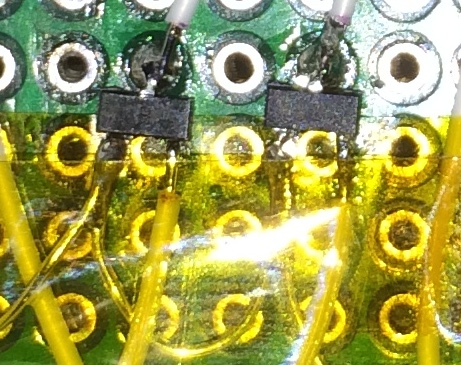
The new motor driver required 5V signaling so I had to add some FETs and pull-up resistors into the mix to step up the 3.3V output signals from the LPC1768. I used a level shifting mechanism based on this one from Sparkfun's converter boards. It uses a surface mount NXP BSS138 N-channel MOSFET which required some tricky soldering to get them and some 0805 surface mount 10k pull-up resistors connected to my board.

I also had to make a modification to the Pololu VNH3SP30 board's PWM input path. These inputs were pulled low with a 10k ohm resistor which when combined with my 10k pull-up resistor resulted in a 2.5V ON voltage rather than the expected 5V. I just removed these two surface mount resistors from the Pololu board since my added pull-up resistors accomplished a similar task while also facilitating the required step-up.
I received my Sphero BB-8 toy earlier this week. Here are some photos of my new toy:
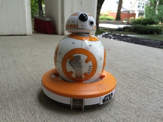
The abilities of this cool little toy are pretty much similar to Christian Poulsen's hacked Sphero. The head is just magnetically coupled to the cart via a fixed stem. This means that it cannot be moved independently of the cart itself. BB-8's head only rotates and tilts when the cart does the same within the sphere. A teardown of this toy by UBREAKIFIX can be seen here.
I think it is about time to get back at this BB-8 project now that the temperatures are starting to get cooler around here!
A very interesting article recently appeared on the official Star Wars website. It discusses the creation and filming of the BB-8 props with the creators themselves. That article definitely definitely set me straight on some misconceptions that I had:
- The BB-8 props, including the one seen on stage at Star Wars Celebration 2015, were all created by Neal Scanlan, Joshua Lee, Matthew Denton, and others at the Star Wars: The Force Awakens creature shop.
- It doesn't appear that Sphero was involved at all in the creation of the functional prop seen on stage at this year's Star Wars Celebration event.
- The functional version of BB-8 seen on stage was created just in time for the Star Wars Celebration 2015 event. It wasn't used in the movie itself.
- The Star Wars: The Force Awakens creature shop created less functional versions of BB-8 to actually be used by the puppeteers in the filming of the movie. Previously I thought some of the scenes in the movie used a fully functional prop as seen on stage at Celebration.
Sphero has created a BB-8 toy that became available for purchase on Force Friday, September 4th. I have ordered one directly from the Sphero website but I don't yet have an ETA on its delivery.
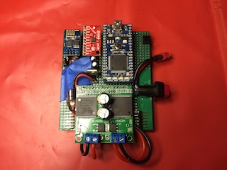
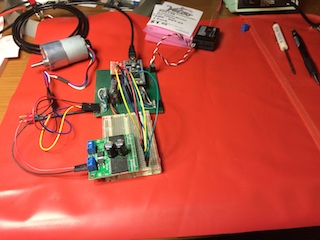
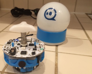
One of my more recent accomplishments on this project has been to move the electronics from this:

to this:

I didn't bother to take the time to create a schematic for the electronic parts that I have hacked together so far for this project. I did however create a few tables to record how signals were routed around the solderless breadboard to help in the migration to the soldered protoboard. What follows are the cheat sheets (tables) that I used for that migration.
| mbed pin | Connection | Notes |
|---|---|---|
| p1 | Gnd | Ground Bus |
| p5 - p8 | SPI | Reserved for SD card |
| p9 | IMU SDA (3) | |
| p10 | IMU SCL (4) | |
| p11 | Left Motor - OUT A | Gray Wire (3) |
| p12 | Left Motor - OUT B | White Wire (2) |
| p13 - p14 | UART | Reserved for debug monitor |
| p15 | Right Motor - OUT A | Gray Wire (3) |
| p16 | Right Motor - OUT B | White Wire (2) |
| p17 | RC Channel 1 | Yaw Channel - Signal is White Wire (1) |
| p18 | RC Channel 2 | Pitch Channel - Signal is White Wire (1) |
| p19 | TB6612FNG BIN2 (11) | Right Motor |
| p20 | TB6612FNG BIN1 (12) | Right Motor |
| p21 | TB6612FNG PWMB (10) | Right Motor |
| p22 | TB6612FNG PWMA (16) | Left Motor |
| p23 - p25 | PwmIn | Reserved for more RC Channels |
| p26 | TB6612FNG nSTBY (13) | |
| p27 - p28 | UART | Reserved for Head Controller |
| p29 | TB6612FNG AIN1 (14) | Left Motor |
| p30 | TB6612FNG AIN2 (15) | Left Motor |
| p31 - p38 | Ethernet & USB | Unused |
| p39 | Vu | 5.0V USB Out - Unused |
| p40 | Vout | 3.3V Bus |
| RC Channel Wire Color | Name |
|---|---|
| White | PWM Signal |
| Red | +5V |
| Black | Ground |
| MPU9150 Signal | Connected To |
|---|---|
| p1 - Gnd | Ground |
| p2 - VCC | mbed Vout 3.3V |
| p3 - SDA | mbed p9 |
| p4 - SCL | mbed p10 |
| p5 - p11 | Not Connected |
| Motor/Encoder Wire Color | Name | Notes |
|---|---|---|
| Black | GND | |
| White | OUT B | Encoder Output 2 |
| Gray | OUT A | Encoder Output 1 |
| Purple | VCC | mbed Vout 3.3V |
| Blue | M2 | Motor Output 2 |
| Green | M1 | Motor Output 1 |
| TB6612FNG Pin | Connected To | Notes |
|---|---|---|
| 1 - Gnd | Ground Bus | |
| 2 - VCC | mbed Vout | 3.3V |
| 3 - A01 | Left Motor M2 | Left Blue |
| 4 - A02 | Left Motor M1 | Left Green |
| 5 - B02 | Right Motor M2 | Right Blue |
| 6 - B01 | Right Motor M1 | Right Green |
| 7 - VMOT | Battery + | Motor Power from Battery |
| 8 - GND | Battery - | Motor Ground from Battery |
| 9 - GND | Ground Bus | |
| 10 - PWMB | mbed p21 | Right Motor |
| 11 - BIN2 | mbed p19 | Right Motor |
| 12 - BIN1 | mbed p20 | Right Motor |
| 13 - nSTDBY | mbed p26 | Enable / Disable Controller |
| 14 - AIN1 | mbed p29 | Left Motor |
| 15 - AIN2 | mbed p30 | Left Motor |
| 16 - PWMA | mbed p22 | Left Motor |
I did spend some time since the last update here attempting to program a Nordic NRF51822 to act as a bridge between Bluetooth Low Energy (BLE) and the UART to make remote debugging easier. I started with this mbed BLE Loopback UART sample and modified it to use the real hardware UART. I also wrote a program for OS X which would connect to this NRF51822 via BLE and expose the serial connection as a TCP/IP socket. The BLE connection would fail mysteriously during my initial testing and it looked like it would take some time to debug so I ended up shelving this project rather than letting it to continue distracting me from my current prototype build. I hope to come back to it in the future since it showed some promise. I will probably investigate a WiFi based solution in the near future.

I know that it has been awhile since I logged anything here but I have actually been working on my BB-8 project. A few weeks ago I received many of the electronic components that I plan to use in my 10" prototype. These components include:
- TB6612FNG motor controller
- Magnetic Shaft Encoders
- Sparkfun MPU-9150 based 9DoF IMU
- Turnigy 9X RC Radio
Since receiving these electronic components, I have been wiring them up on my breadboard and writing lower level software drivers to interface with them. I want to make sure that they all work as expected and share the CPU resources well before I start placing everything inside of my droid. The current firmware has the ability to log the sensor data (IMU, shaft encoder counts, RC radio commands) to the serial port while also allowing the user to manipulate the motors via direct PWM manipulation or via velocity set points in the PID algorithm. One of the new areas for me when working on this code was the proper implementation and configuration of PID loops. I found these two resources to be very helpful:
- http://www.controlguru.com - How to model your system to calculate PID parameters.
- http://brettbeauregard.com/blog/2011/04/improving-the-beginners-pid-introduction/ - How to implement a PID algorithm.
I am almost done with this preliminary software work and will soon begin building a 10" replica of the Sphero control system (just motion with no head).
Cloning now requires a few more options to fetch all of the necessary code.
git clone --recursive git@github.com:adamgreen/bb-8.git
- In the gcc4mbed subdirectory you will find multiple install scripts. Run the install script appropriate for your platform:
- Windows: win_install.cmd
- OS X: mac_install
- Linux: linux_install
- You can then run the BuildShell script which will be created during the install to properly configure the PATH environment variable. You may want to edit this script to further customize your development environment.
Important Notes:
- OS X Mountain Lion and newer will fail to execute mac_install by simply clicking on it. Instead right click on mac_install in the Finder, select the Open option, and then click the Open button in the resulting security warning dialog.
- If the installation should fail, please refer to win_install.log, linux_install.log, or mac_install.log. It will contain the details of the installation process and any errors that were encountered.
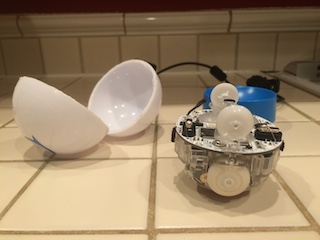
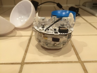
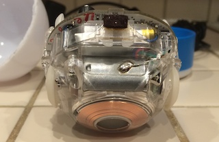
I performed a teardown on a Sphero 2 this week and took some photos of the cool engineering to be found within its sphere:
 Fullsize
 Fullsize
 Fullsize
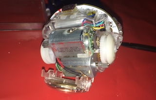
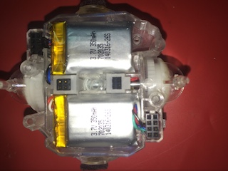
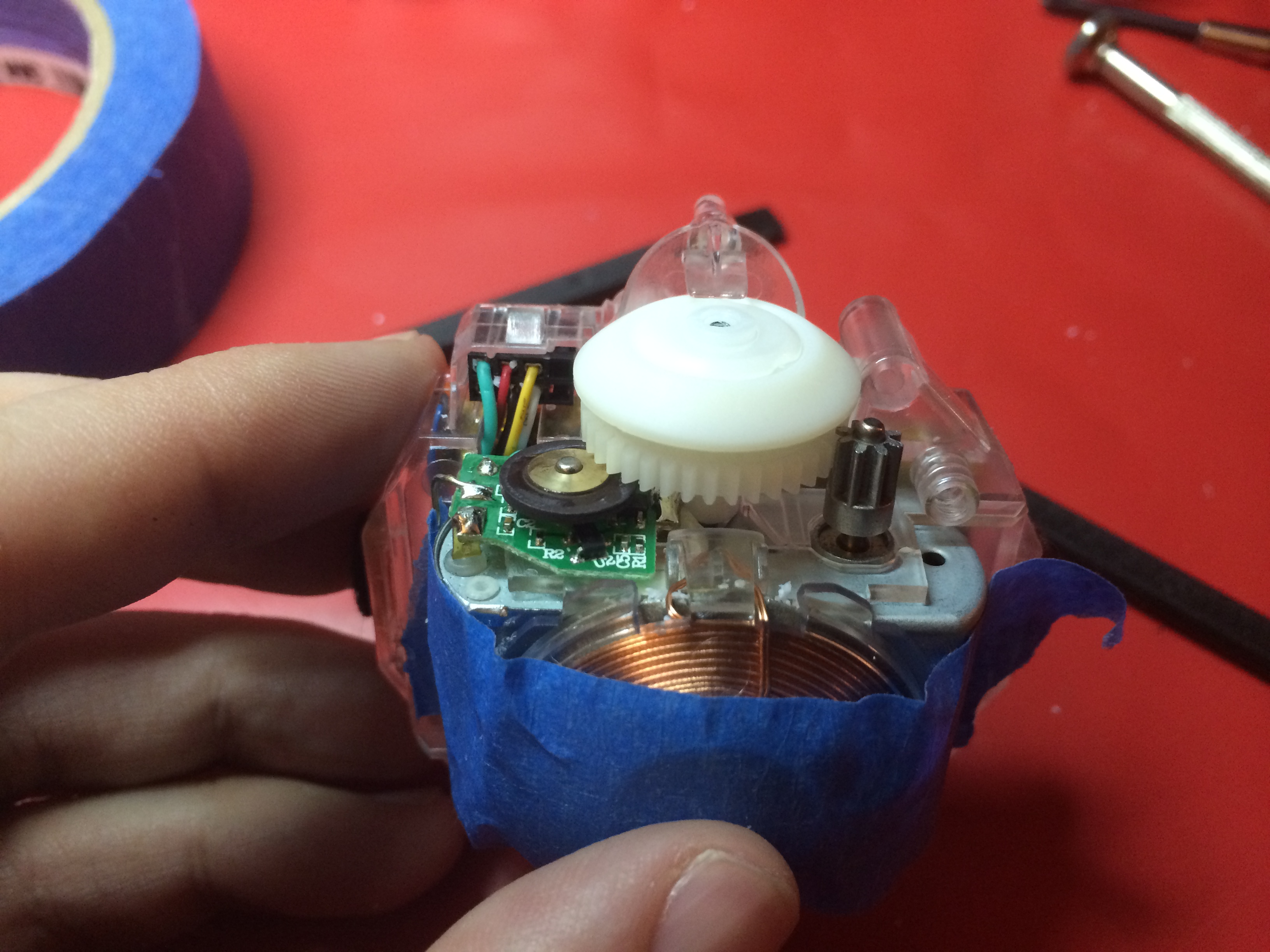
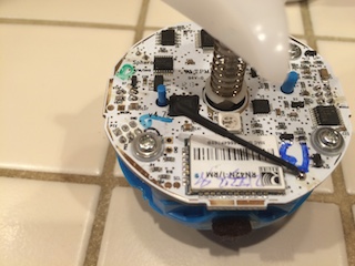
The above 3 photo were taken of the cart before I started to take it apart. The last photo shows the coil on the bottom of the Sphero which is used for inductive charging. In that same photo, you can also see one of the two drive motors just above the coil. Just above the motors is where the LiPo batteries are located. The top of the cart contains the PCB and an additional two wheels mounted to a spring. These two wheels act as the biasing mechanism for the Sphero 2 and guarantee that there is downward pressure on the drive wheels.
 Fullsize
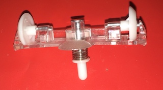
This next photo is a closeup of the spring loaded biasing mechanism.
 Fullsize
 Fullsize
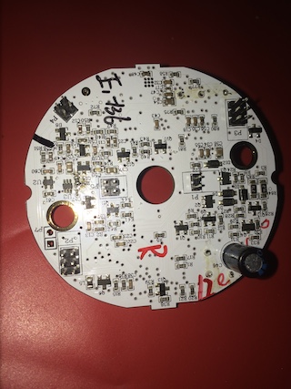
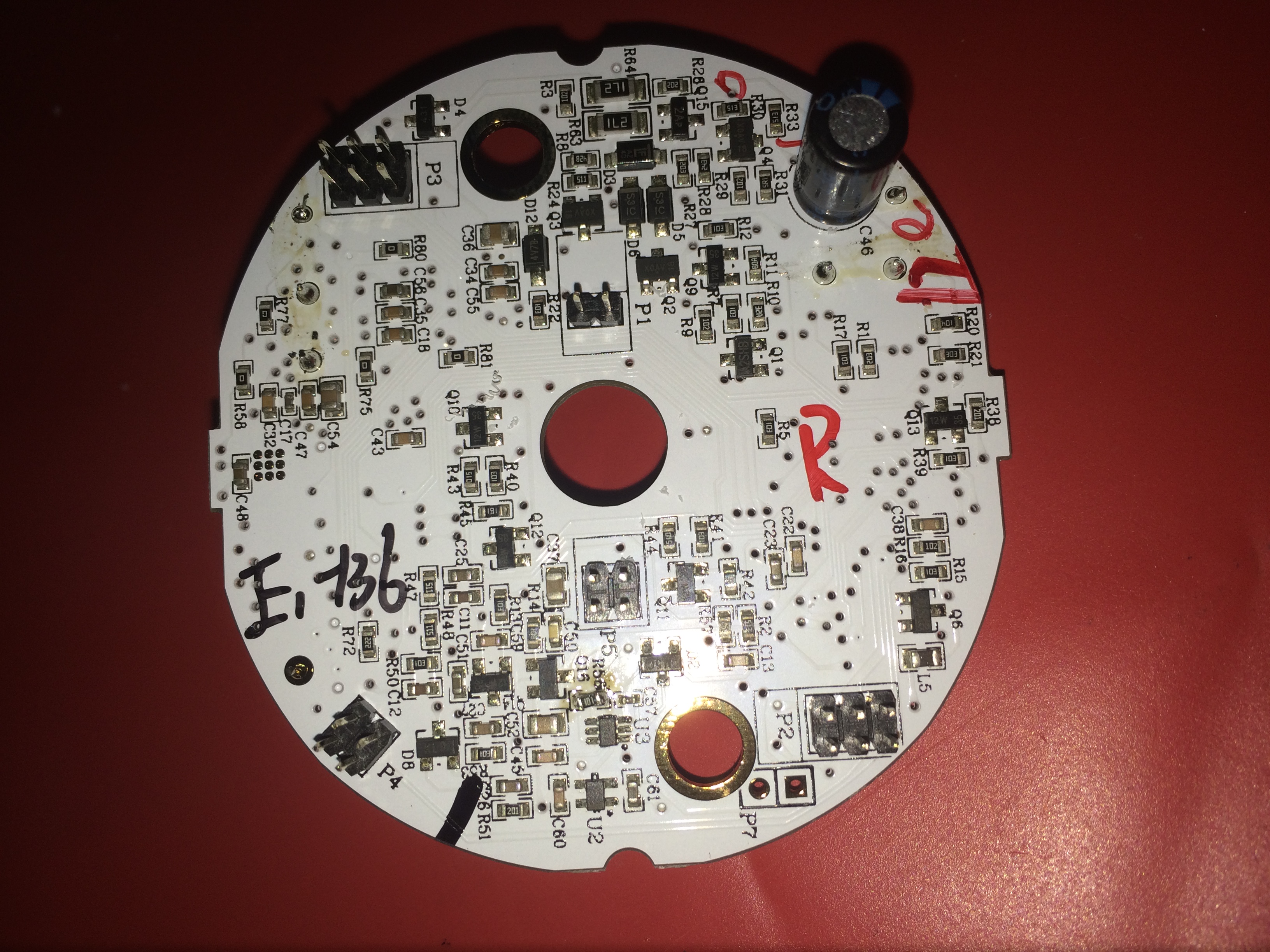
The next photo is of the top of the PCB. The first thing I noticed is that it contains two STM32 processors: a STM32F100RC (Cortex-M3) and a STM32F373C8 (Cortex-M4F).
 Fullsize
The next 2 photos show the bottom of the PCB and where that PCB connects to the rest of the robot. The PCB contains male headers which mate with female headers that are held fast in the body plastics. It is very well engineered. I was surprised to see such a nice and neat interconnect inside of a toy.
 Fullsize
 Fullsize
 Fullsize
I spent some time this week modifying my Sphero 1 to reproduce Christian Poulsen's Sphero BB-8 hack to magnetically couple an external piece of foam to the Sphero's internal biasing mechanism.

My first attempt to complete the project was a failure. I used these 2mm x 1mm neodymium magnets and they just didn't have enough pull to properly capture my foam dome. The following photo shows how I mounted these smaller magnets into 5/32" holes that I had drilled into the biasing unit:

I made a few other mistakes in this first attempt:
- I didn't get the proper concave curve on the bottom of the dome so that it would fit nicely on the outside of the Sphero.
- I had the magnets off center in the foam dome as well.
So the first change I made for the second attempt was to use stronger magnets. I had waited a week for those small 2mm x 1mm magnets to arrive and then I ended up using some larger/stronger magnets that I had purchased at a local craft store a few years ago for another project. I first drilled out the small ones that I previously attempted to use and then used epoxy to attach three of the stronger magnets to the bottom of the biasing unit, as far from the center of the unit as the size of the magnets would allow:
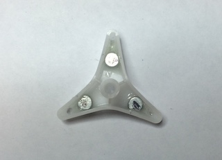
For each of these magnets I had one on the other side of the biasing unit to help position the magnets and hold them in place while the epoxy cured. These helper magnets also worked around the issue that once one magnet was mounted in the biasing unit, the others would be attracted to it as I attempted to mount them.
I purchased a 2" diameter foam sphere from a local craft store and cut it in half to act as a stand-in for the BB-8 head. I know that this foam dome isn't to scale and isn't even the correct shape for a BB-8 head but at this point I just wanted to see the magnetic coupling work. I needed the bottom surface of this dome to match the curvature of the outside of the Sphero toy so I taped a strip of 60 grit sand paper to the outside of the Sphero as shown here:
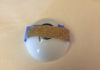
I then rotated the foam dome over this sand paper to get the correct curvature. I did need to dig out some of the foam at the center of the dome with an Exacto knife. This removed material where there was the most to be removed without excessive sanding which would tear at the outer edge of the dome.
The next step was to place another 3 magnets on the base of the foam dome. To make sure that the magnets were spaced/oriented correctly, I placed the Sphero biasing unit with its 3 magnets inside one half of the Sphero body and then sandwiched some wax paper between the outer Sphero body and the 3 magnets. Now the magnets are sitting on the surface of the Sphero body in the required orientation:

I then covered the magnets and wax paper with epoxy so that I could press the foam dome down onto the magnets after I was careful to center them. I just held the dome there for the 10 minutes it took for a basic cure but an elastic band would have been better.
Now I just had to put the Sphero back together. I cleaned up the edges of the cut apart Sphero body using an Exacto knife and then used elastic bands to hold the Shero together while I dapped hot glue around the seam, making sure not to use so much that it would go inside. I also kept the seam pointed down while the hot glue cooled so that gravity wouldn't pull it inside either.

The Sphero does show a problem after my modifications. It doesn't drive as smoothly as it did before my hacks, even when the foam dome isn't attached). It is kind of jerky. I have a few ideas as to what may be causing the problem:
- The inner surface of the Sphero isn't as smooth after I put it back together. This could catch the wheels or biasing unit of the Sphero.
- The holes that I drilled in the biasing unit cause it to catch on the interior surface of the Sphero.
- The strong magnets are throwing off the magnetometer in the electronics and the confusion it causes in yaw rate causes problems for the motion control algorithm.
- The center of mass has moved because of the magnets added to the biasing unit. Maybe this causes some instability in the PID algorithm as it was tuned for the original mass distribution.
If any of these things were the cause then I will be able to diagnose and correct them in the larger models so I will leave further investigation until I see if it happens in those future models.
At this point I want to start working on a half scale (10" diameter) model of the BB-8 which also allows for RC directed motion of the dome.
I decided that today was the day to start trying to hack my Sphero 1 in an attempt to reproduce Christian Poulsen's Sphero BB-8 hack. Before getting my hands on an actual Sphero, I didn't realize that there was as significant of a seam as there is between the two joined hemispheres.

The seam actually made it easier to get a hacksaw blade in between the two hemispheres and start cutting it apart.
Here are a few more photos that I took after pulling my poor little Sphero apart:


Tomorrow I will start trying to track down the rest of the materials that I need to complete this Sphero hack. That includes some strong magnets and foam to create a captured head.
Last weekend I saw new videos from the Star Wars Celebration 2015 event that took place last week. The video that really caught my eye was the one showing a new spherical droid rolling around on the stage. This new droid goes by the name of BB-8. I had seen cameos of this new droid in the Star Wars The Force Awakens movie trailers but I just figured it was all CGI, Computer Generated Imagery, so never really gave it much of a second thought. I mean I was interested to see it in the theater when the movie releases but it never triggered any robot building ambitions. It was magical to see an actual working BB-8 prop on the stage in that Star Wars Celebration video. The head just seems to levitate over the rolling spherical body. Could I build one of these magical looking bots myself?
A great conversation started up on Hackaday discussing how this BB-8 prop actually works. The key takeaways that I got from the Hackaday comments were:
- Orbotix / Sphero is the company behind the functional BB-8 prop.
- Orbotix / Sphero already markets a spherical robotic toy that works like the BB-8 prop, it's just missing the head.
- Orbotix / Sphero has patents which explain how the rolling spherical base and captured head function:
- Orbotix / Sphero is most likely going to release a functional BB-8 toy in time for the release of the Star Wars The Force Awakens movie and the 2015 holiday season.
There is also some discussion about the BB-8 droid on the R2 Builders Club Yahoo Group.

How should I proceed with building a BB-8 replica? I would like to build a life size replica, which I believe to be about 18 inches in diameter, but I want to start with a few smaller replicas first.
- I would first like to replicate Christian Poulsen's Sphero BB-8 hack.
- I ordered a Sphero 1.0 bot from Amazon earlier in the week and it arrived today.
- I plan to start the hack this weekend by cutting the sphere in two but only after I get in some more play time.
- I don't plan to paint it to look like the BB-8. I just want to reproduce the captured foam head portion of the hack.
- A half scale replica that would be fully functional. This is where I would work out head movement / control.
- A full scale replica. This replica should be fully functional and painted to match the actual prop as closely as possible.