Version: 2.1
- Description
- Use Case
- Material Types
- Color Spaces
- Texture Color Interpretation
- Parameter Functions
- License
- Terms and conditions
- References
The Advanced Material Data Format (short AMDF) is a unified description of complex materials. Within this format, all parameters that are needed for a proper shading of virtual materials are stored in an XML file.
Its basis is the physically based shading model that was introduced in 2012 by Brent Burley for the Walt Disney Animation Studios1. This is a "principled" model that was developed to be easy to use rather than physically correct. In 20152, an updated version of this Disney BRDF was published, which has some improvements regarding subsurface scattering and Fresnel, as well as additions like transmissions and a thin-surface approximation. We are adopting some of those changes in our material shading model.
To define the structure of the AMDF we use an XML Schema Definition file. The exact structure can be seen in the corresponding XML schema documentation. The base of an AMDF is one of five material types which will be described in the following.
This XML schema is used to define the visual appearence of virtual materials. It is independent from a specific 3D rendering software. The only restriction is, that the application has to implement the Disney BRDF standard as described above, to get comparable results.
adidas is not responsible for the usage of this schema for different purposes than the one described in this section.
Our material data format can cover different kinds of material types. Each of them has a set of meta-data attributes to hold additional data like an ID or the creation data.
This chapter lists all those types and describes how those different materials must be handled and which parameters are used.
A Material describes a set of physical materials packed together into one file as sub-materials. This clustering is done to associate multiple sub-parts of a material with different structure (like a fabric with multiple knit structures) with the same ID. An example can be seen in Figure 1.
In later processes, multiple sub-materials can be placed on one part of a geometry. By applying alpha/mask maps to those sub-materials, they are masked out against each other. Because these alpha/mask maps are depending on a specific 3D model and thus part of the geometry, they aren't stored in the AMDF, as this is only a material description format.
A sub-material stores the front facing side of the material and can as well hold the side and back faces if needed. Each of those faces can then consist out of one or multiple layers. The material layers contain the actual shading parameters, together with some additional values, e.g. for the possibility of recoloring it (see HSV Shift).
 |
 |
|---|---|
| Figure 1: Multi-sub-material with different knit structures | Figure 2: Multi-layered material. |
The layers of a multi-layered sub-material are blended against each other using alpha maps. Here, the alpha map is part of the actual material layer (other than for sub-materials) as it defines, where holes are (e.g. in a knitting structure). For ordering these layers, the mandatory order attribute is used. The topmost layer has the lowest value and it's increasing as you peel the layers to the bottommost.
An Emboss represents a surface structure, which can be applied to a part of geometry, for example a leather structure on a plastic material. Embosses can have both a normal and displacement map. Which one of those is used is selected when applying the emboss to a material in the render software.
A normal map of an Emboss must be blended together with the normal maps of the sub-material that it is applied to using the calculation shown in 5.2. When using a displacement map, then its values are simply added to the values of the displacement maps of the sub-material.
The roughness and specular values of the Emboss will override the corresponding values of the sub-material. If no roughness and/or specular value is provided, then the values of the sub-material are used.
Color describes a single color, which is later used to recolor a single material layer. This recoloring is done as shown in HSV Shift by using the baseColor and originalColor of the material layer, that the color is applied to, and the colorValue of the Color.
The AMDF is capable of handling different kinds of colors. The different types are described hereafter.
Normal Colors are the simplest type of color as they are only replacing the color of the underlying material using the algorithm described in HSV Shift.
Solar Colors are a special kind of color that absorbs UV radiation and re-emits this light in the visible spectrum. In existing shading approaches this is done using an emission shader, but this isn't really accurate due to the fact, that it also emits light, when no light source is present. An artistically friendly solution is to simply oversaturate and brighten the colorValue by a bit and store this as an offset in the colorTweak.
Metallic Colors are material like colors, for example a material made out of a metallic yarn. It overrides the parameters of the underlying material layer with the parameters that are set in the Metallic Color.
A Treatment is a thin coating of varnish or a foil that is applied to a part of geometry. To be physically correct, a transparent material with a defined IOR and a thickness would have to be used but as it's only a thin translucent surface without noticeable refraction, it can be replaced by a specular clearcoat highlight instead.
In the shading step, the shading value of the clearcoat simply needs to be added to the shading value of the underlying sub-material. This effect is shown in Figure 3.
 Figure 3: Left: sub-material; middle: treatment; right: combination of
sub-material and treatment
Figure 3: Left: sub-material; middle: treatment; right: combination of
sub-material and treatment
Note: If no clearcoat normal is provided in the AMDF, it adopts the normal of the underlying material. Else the clearcoat normal is used directly (see Figure 3).
Prints describe various different types of structures that can be put on a Material. This can reach from any type like logos (either an embossed or a printed logo) or graphics. As a print can be made out of a material, like a varnish, it can have its own material parameters. All provided parameters (and only the provided ones) would override the parameters of the underlying Material. For normal maps, a blend mode can be chosen when applying the Print. The blend mode isn't stored in the AMDF so that the artist has the freedom to choose it when applying the Print onto a Material depending on what he or she wants to achieve.
A Print can consist out of different parts. These parts are masked out against each other using the mandatory maskMap.
There are different ways of blending the normals of the Print with the underlying structure. This blending is depending on what kind of process is used to apply the Print and also of the physical parameters of the used print material, like viscosity. Figure 4 visualizes the possible blend modes.
 Figure 4: Side view of the layering of the different material types. This
shows the different normal blend modes a print can have.
Figure 4: Side view of the layering of the different material types. This
shows the different normal blend modes a print can have.
In the following the different blend modes are described in detail.
This blend mode is used when having a print which is applied on top of a material and thus only interacts with the topmost layer. This can be either a Material (which may have an emboss applied) or a Treatment. The print follows the shape of the topmost layer and also keeps its own structure. For blending the normals, the algorithm described in chapter 5.2 is used.
Blend All uses the same algorithm as Blend Topmost but applies it to all of the underlying layers. This mode is used for Prints that are embossed into the material. An example would be to have an embossed logo.
The Replace All blend mode is the simplest mode which overrides the normal map of the underlying Material.
In the AMDF the color space of constant colors need to be defined to correctly interpret the color values correctly. These color spaces have been restricted to "linear", "sRGB" and "AdobeRGB".
Textures can be used to store simple data (e.g. roughness maps), vectors (e.g. normal maps) or actual color data. Other than color textures, the values of simple data and vector maps should be used as they are and not be color corrected with the color space stored in the texture (none-color data). For this purpose, a colorInterpretation attribute exists for referenced textures, which can be either set to "ColorData" or "NoneColorData".
To recolor a virtual material layer, a colorization model has been proposed, which is capable of reproducing the effect that the same color on different materials comes out differently. The idea is as follows:
- A real material is colored using a given color (originalColor of a Material).
- It is analyzed how the color looks on the material (baseColor of a Material).
- The difference (e.g. less saturated and brighter) is cloned using a given target color (colorValue of a Color).
The pseudo code for this approach looks like this:
rgbColor recolorTexture(
    Texture input,
    rgbColor pdmColor,
    rgbColor targetColor
    TexCoord uv)
{
    unsigned int image_width = input.width;
    unsigned int image_height = input.height;

    hsvColor hsv_pdm = RGBtoHSV(pdmColor);
    hsvColor hsv_target = RGBtoHSV(targetColor);

    // get the pixel color from the texture and
    // convert it to HSV
    rgbColor baseColor = tex2D(input, uv);
    hsvColor hsv_base = RGBtoHSV(baseColor);

    // compute hsv difference of pixel compared to pdmColor
    hsvColor hsv_diff_to_pdm = hsv_base - hsv_pdm;

    // kill difference in hue
    hsv_diff_to_pdm.h = 0;

    // apply difference on target color
    hsvColor hsv_pix_target = hsv_target + hsv_diff_to_pdm;

    // desaturate the output depending on the saturation
    // of the target color
    hsvColor desat_hsv_pix_target = desatColor(hsv_pix_target, hsv_target);

    rgbColor rgb_pix_target = HSVtoRGB(desat_hsv_pix_target);

    return rgb_pix_target;
}
As a slight red tinge was observed for desaturated target colors, the output color is desaturated using the following function:
hsvColor desatColor(
    hsvColor recoloredPixel,
    hsvColor targetColor)
{
    float s_t = targetColor.s;
    float s_d = 1.0 - pow(1.0 - s_t, 5.0);

    hsvColor c_d;
    c_d.h = recoloredTexture.h;
    c_d.s = s_d * recoloredTexture.s;
    c_d.v = recoloredTexture.v;

    return c_d;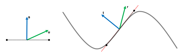
}To process both a normal and an emboss map, those two have to be mangled
together to get one resulting normal map. As the color values are a
representation of 3D vectors (with vec3 n = n_col * 2.0 - 1.0), they
can't simply be blended together. For a correct blending, the
detail/emboss normal (u) has to be reoriented to follow the base
normal (t) as it is shown in the following graphic3:
The following pseudo code shows a simple solution for this problem:
color mangleNormals(
    Texture normal,
    Texture emboss,
    TexCoord uv)
{
    rgbColor t = tex2D(normal, uv).rgb * rgbColor( 2,  2,  2) + rgbColor(-1, -1,  0);
    rgbColor u = tex2D(emboss, uv).rgb * rgbColor(-2, -2,  2) + rgbColor( 1,  1, -1);
    rgbColor r = normalize(t * dot(t, u) - u * t.z);

    return r * 0.5 + 0.5;
}For remapping of the value maps (e.g. the specular or roughness map), a simple brightness/contrast approach is used4. The pseudo code is as follows:
float remapTextureValue(
    Texture valueMap,
    TexCoord uv)
{
    return (tex2D(valueMap, uv).r - 0.5) * (1.0 + contrast) + 0.5 + brightness;
}Copyright © 2018, adidas AG, Released under the Apache 2.0 License
adidas publishes this open source software with the aim of helping the community with our tools and libraries which will be also useful for other people.
It means that the published code is working and adidas wants you to work with it, however, adidas is not responsible for any issue which could happen using this software in a production environment. So, be careful using this code in a risky environment, such as medical or autonomous car applications.
If you want to contact adidas regarding this, you can mail us at software.engineering@adidas.com.
For further information open the adidas terms and conditions page.
- Physically-Based Shading at Disney, Brent Burley, Walt Disney Animation Studios, Aug 31, 2012, https://disney-animation.s3.amazonaws.com/library/s2012_pbs_disney_brdf_notes_v2.pdf
- Extending the Disney BRDF to a BSDF with Integrated Subsurface Scattering, Brent Burley, Walt Disney Animation Studios, 2015, http://blog.selfshadow.com/publications/s2015-shading-course/burley/s2015_pbs_disney_bsdf_notes.pdf
- Blending in Detail, Colin Barré-Brisebois and Stephen Hill, Jul 10, 2012, http://blog.selfshadow.com/publications/blending-in-detail/
- Chapter 4. Point operations, Brightness + Contrast, GIMP, http://pippin.gimp.org/image_processing/chap_point.html