Support for Sonoff D1 Dimmer #7598
Comments
|
Was wondering the same thing... |
|
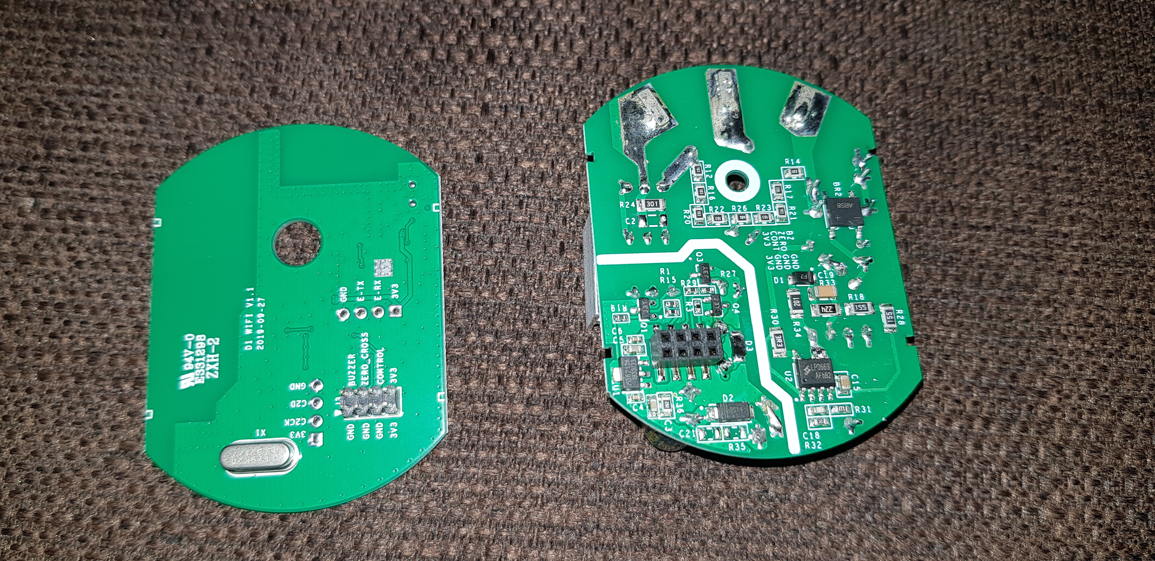
Please, provide photos of the internal board. |
|
|


|
Thanks. Really good photos. This device has an ESP8285 so Tasmota can be flashed but as it has also some extra circuitry, a reverse engineering is needed to make or adapt a driver for that. |
|
I love the OTA switch |
|
I have one flashed with Tasmota myself. I tried all the GPIO pins as relays and that doesn't seem to do anything. Pretty easy to flash and didn't even have to solder or mess with the stupid DIY mode. Pins were open and GPIO 0 is broken out to a pad for you to touch to ground while applying power. |
There is no relay on this board. It’s just a power mosfet. That mosfet controls the voltage for the high side output. Under the mosfet is an optocoppler that is linkt to the control pin of the header. So, I think there Must Be some kind of analog signal to control this coppler. But I ask myself, for what is this Buzzer? |
The dimmer can also RF 433Mhz. There is a remote control for the dimmer, the instruction manual says that if you connect the remote control to the dimmer, the dimmer beeps briefly. |
|
@kugelkopf123 yep, that's why I tried the relay pins to see if we needed to do PWM but alas no... thinking maybe some sort of serial signal to another chip but I haven't googled the other ones yet. |
|
I have some better pictures posted here and here. I have traced Tx and Rx from the ESP chip through a 1k resistor and to the pads that are labeled the same close to the BB10. When I grounded them it stopped being able to dim. So I think you are right that it uses serial to tell the MCU how to dim. This is similar to what Tuya does. How can I monitor the serial lines so I can see what is being sent over them while I am dimming? |
If it is plain old serial communication, one-way sniffing should work with just a normal USB/serial adapter (like also usable for flashing), and possibly experiment to find the right bit rate. |
|
Hi, what about https://templates.blakadder.com/sonoff_D1.html ? but TRIAC = leading edge = 🤕 |
Does anyone know if this works? Not so experienced with templates so scared to try it before knowing if it works. |
|
Any luck with this or outlook on it... I would help but don't know where to look. Currently waiting to pull the trigger either on the Sonoff D1 or Shelly Dimmer |
|
That's a negative, I figured it wouldn't work as I tried a relay output on it and nothing. I tried this PWM template and nothing comes out of it. |
|
Are you using an oscilloscope to test? |
|
Tried and true old school light bulb. |
|
I feel that the high voltage board is the equivalent of this Here is lib for that module with esp code, should be very similar for D1 |
|
I confirmed that sending 3.3v to buzzer pin turns on a buzzer... cute. I don't intend to flash it with hub based firmware as I prefer IOT mode without hub. But what I am struggling with is how to turn it on and off locally. I tried shorting each pin to 3.3v or ground, but only one pin (c2ck) turns it off when grounded and nothing turns it on. On the sonoff basic, I have been using this approach for hooking up capacitive touch sensors by sending ground pulse to the reset button. I do need a way to be able to physically turn these on and off, without remote. Really strange that they got rid of the reset button. Is there gpio that I could use as a reset button? |
|
It's not gonna be a matter of figuring out which I/O does what. |
|
It seems odd that Sonoff would make the D1 so easy to flash a DIY firmware, but then make it difficult to actually control the dimmer from that firmware. |
They did'nt. No DIY mode (which sucks anyway), they just did not go out of their way to make flashing hard. While it would have been nice of Itead to publish tinkering info, that is just not priority in a tiny market. |
|
I just bought a Sonoff D1 and it came with a 433MHz remote control. |
Sorry to hear that you bought Sonoff D1, it is trash. I purchased about ten of them few years back and am slowly replacing them with Moes Tuya Smart double-din dimmers that you can find on Ali But to answer your question, yes you can use it with the remote or with other compatible smart RF learning remote hub without wifi |
|
What did you find wrong with the D1? I've only the one running Tasmota, but
it has been smooth as butter...
…On Thu, Nov 2, 2023 at 8:07 PM sandeep-ma ***@***.***> wrote:
I just bought a Sonoff D1 and it came with a 433MHz remote control. Is it
possible to control the D1 with this remote control without first
registering the D1 to the Sonoff cloud at all and never use the EWLink App?
Sorry to hear that you bought Sonoff D1, it is trash. I purchased about
ten of them few years back and am slowly replacing them with Moes Tuya
Smart double-din dimmers that you can find on Ali
But to answer your question, yes you can use it with the remote or with
other compatible smart RF learning remote hub without wifi
—
Reply to this email directly, view it on GitHub
<#7598 (comment)>,
or unsubscribe
<https://github.com/notifications/unsubscribe-auth/AL2QNZJ5QUAZKYJETMVXOTLYCP4QVAVCNFSM4KLQUEV2U5DIOJSWCZC7NNSXTN2JONZXKZKDN5WW2ZLOOQ5TCNZZGE2DMOBRGY3Q>
.
You are receiving this because you commented.Message ID:
***@***.***>
|
|
Never had any problems with it either. Runs absolutely flawlessly. |
|
They are too bright even at 0% |
|
I concretize. I have flashed it with tasmota and no problems at all. Ghost switching was already discussed in detail. |
|
Given that this is a Tasmota forum, the assumption was that Tasmota was
misbehaving on the unit, which isn't the case.
…On Thu, Nov 2, 2023 at 9:47 PM sandeep-ma ***@***.***> wrote:
They are too bright even at 0%
They go on in the middle of the night due to no reason
Very bulky
Cannot use same login from multiple devices
Access is restricted by world regions; same user cannot access switches in
north america and asia
More expensive
Higher failure rate
------------------------------
—
Reply to this email directly, view it on GitHub
<#7598 (comment)>,
or unsubscribe
<https://github.com/notifications/unsubscribe-auth/AL2QNZMJJ3YZKQHVBAMAIFDYCQIGNAVCNFSM4KLQUEV2U5DIOJSWCZC7NNSXTN2JONZXKZKDN5WW2ZLOOQ5TCNZZGE2TQMZUGYYA>
.
You are receiving this because you commented.Message ID:
***@***.***>
|
I did not mean to imply an industry wide failure rate analysis. Just my own experience with about 10 of these and about 10 of the other one. Regarding ghost switching, I am aware that it starts occuring after a power outage. And can be fixed by resetting the RF remote. In my case, there is one that is not getting reset at all. Moreover, why take on that headache when you can get something better for less. |
|
Well, whether the D1 is crap or not - I just got mine and I intend to put to the test before giving up. |
|
I removed the resistors and had no issues whatsoever... full functional |
|
Well, Sandeep-ma obviously took the wrong turn and never changed the firmware on his D1. No idea why he posted about it on a Tasmota forum. |
|
Good night Buenas noches |
|
1st part solved. JST12Serie 12A TRIACs
|


The 433MHz RF remote still works without the resistors? I had ghost switching with Tasmota. The module was installed in an inconvenient location so I didn't want to remove it for hardware mods. Instead, I switched to ESPHome and haven't had any problems with ghost switching since. Disclaimer: I do not use the RF remote. |
Can you please elaborate on that statement? |
|
The resistors completely cut the connection from the RF part. So the remote will not work anymore. |
|
Right. That's what I thought. I mentioned that I don't use the remote because even though I haven't removed the resistors, I did set the ESPHome configuration |
|
I have just bought a couple of these D1 dimmer devices to try, but I am wary of the ghost switching mentioned. Looking at the ESPHome code, they appear to detect a dimmer state/level change, and revert the value back to the last “stored” value that was sent via native ESPHome commands. This means in Tasmota terms, to implement an equivalent of
If you wanted to retain the use of the RF remote ( Whilst I can read and understand code, I’m not very good at programming it, so have no idea where to start to implement an equivalent for Tasmota. I cannot see any such implimentation in the Tasmota code, so forgive me if there is something already in there. I have not as yet seen any spurious switching with a physically unmodified device - all ICs and resistors are still in place, and I don't have any RF control devices paired or otherwise linked to the the D1. I am using Tasmota 13.3.0, not ESPHome. |
|
Hello! I want to install the Sonoff D1 Dimmer inside a floor lamp. So I will not know witch is going to be Neutral or Line. Is it going to work? |
|
Why wouldn't it? Also what country and specification are we talking about? Would have been helpful to include that. |
Cables inside the lamp: |
Thank you for your answer! I live in Greece, so we use EU standards. Blue = Neutral, Brown = phase. I will connect the D1 inside the floor lamp with the respecting colors. So, as you say, I will not have any problem how I'll plug the floor lamp to the wall outlet as I understand. It will work both ways! Right? |
|
Yeah, you generally do not need to be very exact about phase/neutral, unless maybe if you have protective earth too. Still, I do like to do it "right", like when having a relay cutting off phase instead of neutral. While both works, having the phase go directly to the consumer does mean having live on more wire than needed. But it still works. |
|
Hello All |
|
Why do you want to flash Tasmota on the D1 ? |
|
You can use the normal Release binary of version 13.3.0. http://ota.tasmota.com/tasmota/release/tasmota.bin.gz This one or any other in your language. |
|
Great thanks for the feedback
Any recommended template you are using?
Le lun. 12 févr. 2024, 22:31, fapoo ***@***.***> a écrit :
… You can use the normal Release binary of version 13.3.0.
Works Fine for me.
—
Reply to this email directly, view it on GitHub
<#7598 (comment)>,
or unsubscribe
<https://github.com/notifications/unsubscribe-auth/ARU4ZK6QZQSWSDET4XNOLJ3YTKC2HAVCNFSM4KLQUEV2U5DIOJSWCZC7NNSXTN2JONZXKZKDN5WW2ZLOOQ5TCOJTHE3DCOBXGQ4A>
.
You are receiving this because you commented.Message ID:
***@***.***>
|
|
Recommended template: https://templates.blakadder.com/sonoff_D1.html |
|
Thanks!
Le mar. 13 févr. 2024, 01:33, sfromis ***@***.***> a écrit :
… Recommended template: https://templates.blakadder.com/sonoff_D1.html
—
Reply to this email directly, view it on GitHub
<#7598 (comment)>,
or unsubscribe
<https://github.com/notifications/unsubscribe-auth/ARU4ZK4TX2ZHBAJEN6GJ5F3YTKYEHAVCNFSM4KLQUEV2U5DIOJSWCZC7NNSXTN2JONZXKZKDN5WW2ZLOOQ5TCOJTHE4DOMZQGAYA>
.
You are receiving this because you commented.Message ID:
***@***.***>
|
|
Flashed and works perfectly thanks ! but ... there is a but |
Have you looked for this feature in other issues and in the docs?
Yes
Is your feature request related to a problem? Please describe.
A clear and concise description of what the problem is.
I cant't find a Template for this Device.
Describe the solution you'd like
A clear and concise description of what you want to happen.
Sonoff has released a new dimmer, the Sonoff D1 dimmer. Is Tasmota compatible with this dimmer, if not, is it possible to add it?
Thanks


Describe alternatives you've considered
A clear and concise description of any alternative solutions or features you've considered.
Only Support.
Additional context
Add any other context or screenshots about the feature request here.
(Please, remember to close the issue when the problem has been addressed)
The text was updated successfully, but these errors were encountered: