-
-
Notifications
You must be signed in to change notification settings - Fork 45
Debrick
Built in firmware update function writes data to flash.
SYSTEM.VSB has 0x100 byte header, remaining 0x200000 is the application.
ROM Bootloader (RBL) loads Secondary Bootloader (SBL) from Application Image Script (AIS) into On-Chip RAM at 0x80000000.
SBL loads app into external RAM at 0xc0000000.
Most of this guide assumes you are using a debugger and don't have a working electribe available.
See RPi and OpenOCD below.
It may be easier to read the full flash contents from a working electribe and write it to the bricked electribe.
It may also be possible to read the flash from the bricked electribe, edit it with the correct firmware and write it back.
See RPi and FlashROM below.
Commands marked '$' should be executed in a bash shell.
$ this_is_a_bash_command
Commands marked '>' should be executed in the openocd shell.
> this_is_an_openocd_command
Depending on your system configuration, openocd command may require sudo privileges.
If it boots up to a prompt asking for update, it's probably not bricked.
Complete only Prepare SD Card step and reboot.
Device should flash back to factory firmware.
If this does not work, complete all steps in RPi and OpenOCD section.
If the screen lights up but boot does not complete, the secondary bootloader (SBL) is probably ok but the app is corrupt.
Complete all steps in RPi and OpenOCD section.
When the CPU firmware boots, it queries the version of the MCU firmware.
If it does not receive the answer it is expecting, the CPU initiates an MCU firmware update.
If it is not getting past '00/12' it is likely the CPU can't communicate with the MCU.
The most likely culprit is the ribbon cable connecting the motherboard to the panel board, try re-seating or replacing it.
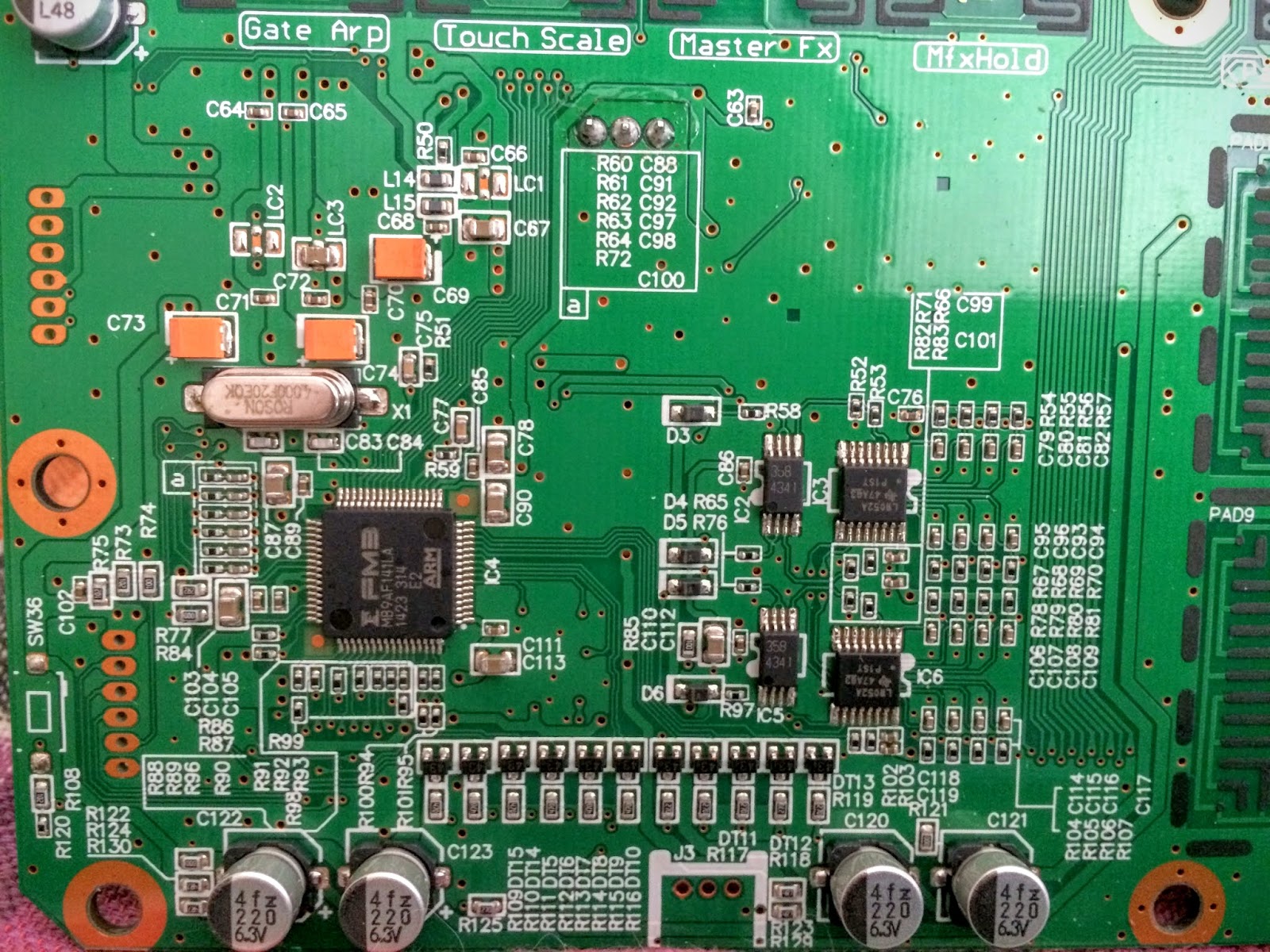
If that doesn't work, you can check if the MCU on the panel board is running by attaching a logic analyser to the serial port.
J3 shown bottom centre in this photo.
If the screen does not light up, either SBL is corrupt or there is a hardware issue.
Check the power supply and try re-seating the ribbon cables for the screen and motherboard.
We can check for processor activity by reading from the serial port (J3 shown bottom centre in this photo),
or attaching a debugger to the CPU JTAG port (J9 on the left in this photo).
If SBL is corrupt, execution will crash somewhere in On-Chip RAM (0x800nnnnn) or ARM RAM (0xffffnnnn).
To fix a corrupt SBL, we need to dump the bootloader from the RAM of a working electribe.
Either run this script against a working hacktribe installation, or use OpenOCD to dump the On-Chip RAM of any working electribe 2.
See Get Secondary Bootloader step below.
We also need BOOT.VSB, a backup of the AIS from flash memory with a file header added (not documented yet).
Once you have a bootloader backup, follow the steps in RPi and OpenOCD, stop before Write Firmware step.
Once the app has booted, first run the built in update function with BOOT.VSB to write the AIS to flash.
Then follow RPi and OpenOCD, using SYSTEM.VSB to write the app to flash.
When the device powers up, the power only stays on once the firmware app is running.
This may happen when it crashes, but won't happen when it starts up with a debugger attached.
Connect a toggle switch across J4, the unpopulated 2 pin header shown near the top right of this photo, to the right of C202 and C137.
The motherboard will need removing to reach it, but if you put the switch on some long thin wires you can replace the motherboard after.
Each time the device is powered up while debricking, use the toggle switch instead of the power button. This will keep the power supply active.
Once the firmware app starts booting, turn the toggle switch off or it will shutdown as soon as it has booted, thinking the power switch is held.
Install OpenOCD and connect RPi GPIO to e2 CPU JTAG Header (J9).
RPi / OpenOCD:
- https://iosoft.blog/2019/01/28/raspberry-pi-openocd
- https://learn.adafruit.com/programming-microcontrollers-using-openocd-on-raspberry-pi/overview
e2 J9:
Config files:
In openocd.cfg, the comment at line 20 # Header pin numbers: 23 22 19 21 shows the physical location of the pins on the header, the command at line 21 bcm2835gpio_jtag_nums 11 25 10 9 uses the pin numbers as the CPU sees them.
Using pin numbers by physical location:
E2.J9 <-> RPI.GPIO

GND <---> 20 (or any other ground pin)
TMS <---> 22
TCK <---> 23
TRS <---> 26
TDI <---> 19
TDO <---> 21
Prepare SD card with SYSTEM.VSB at correct path for device.
(Ensure SYSTEM.VSB is correct firmware for device as it was from the factory).
Factory Synth (e2, grey or blue):
KORG/electribe/System/SYSTEM.VSB
Factory Sampler (e2s, black or red):
KORG/'electribe sampler'/System/SYSTEM.VSB
Remove the header from the firmware update file, leaving only the binary which is loaded into RAM:
$ dd if=SYSTEM.VSB of=SYSTEM.bin bs=256 skip=1
First we need the Secondary Bootlader, which sets up the hardware then loads the app from flash memory into external RAM.
Power up bricked electribe and it will crash.
If it was bricked by a corrupt firmware update, it has crashed in the app (at 0xc0nnnnnn) and the bootloader is fine.
Attach openocd and connect to the telnet server:
$ openocd -f path/to/openocd.cfg

$ telnet localhost 4444
Halt the processor and dump the bootloader from On Chip RAM at 0x80000000:
> halt
> dump_image SBL.bin 0x80000000 0x5e40
With openocd still running, power off bricked electribe and power it back on.
Then stop openocd with Ctl+C and run it again.
This time the electribe should be waiting in the ROM bootloader (RBL) in ARM RAM somewhere around 0xfffd5990-0xfffd599c.
Halt the processor in the ROM Bootloader and load the Secondary Bootloader into On Chip RAM at 0x80000000:
> halt
> load_image SBL.bin 0x80000000
Set the Program Counter register to the start of the Secondary Bootloader:
> reg pc 0x80000000
Set a breakpoint at start of app in external RAM at 0xc0000000:
> bp 0xc0000000 4
Resume the processor and wait for it to hit the breakpoint:
> resume
When the SBL hands off to the app at 0xc0000000, the corrupt firmware has been loaded from the flash into external RAM but has not begun to execute.
We overwrite the corrupt firmware with the factory firmware before continuing from the breakpoint:
> load_image SYSTEM.bin 0xc0000000
Resume the processor and the factory firmware should boot correctly:
> resume
When the logo appears, switch off the toggle switch soldered across J4 (do not disconnect the power).
If the switch remains closed, the firmware will think the power button is held down and will shutdown as soon as it is finished booting.
Once booted, use built in firmware update function to write firmware to flash before powering off.
Reading and writing the SPI flash directly is probably easier than getting a debugger set up.
When I tried this using cheap connectors I couldn't get a clean write and ended up corrupting the bootloader as well.
I have used this process on other devices without issues.
Use a Pomona 5250 clip and keep the wires as short as possible.
Read the full contents of the flash using FlashROM.
Read at least 3 times (ideally more) and make sure every read is the same.
If you have a working electribe, read the flash and write it to the bricked electribe.
If not, read the flash from the bricked electribe, then edit it to contain the correct firmware.
Remove the header from the firmware update file, then write it to 0x20000 in the binary read from the flash.
Write the result back to the flash.
This will only work if only the app section of the flash was corrupt.