By Brian Kaplan & Adam Elghor
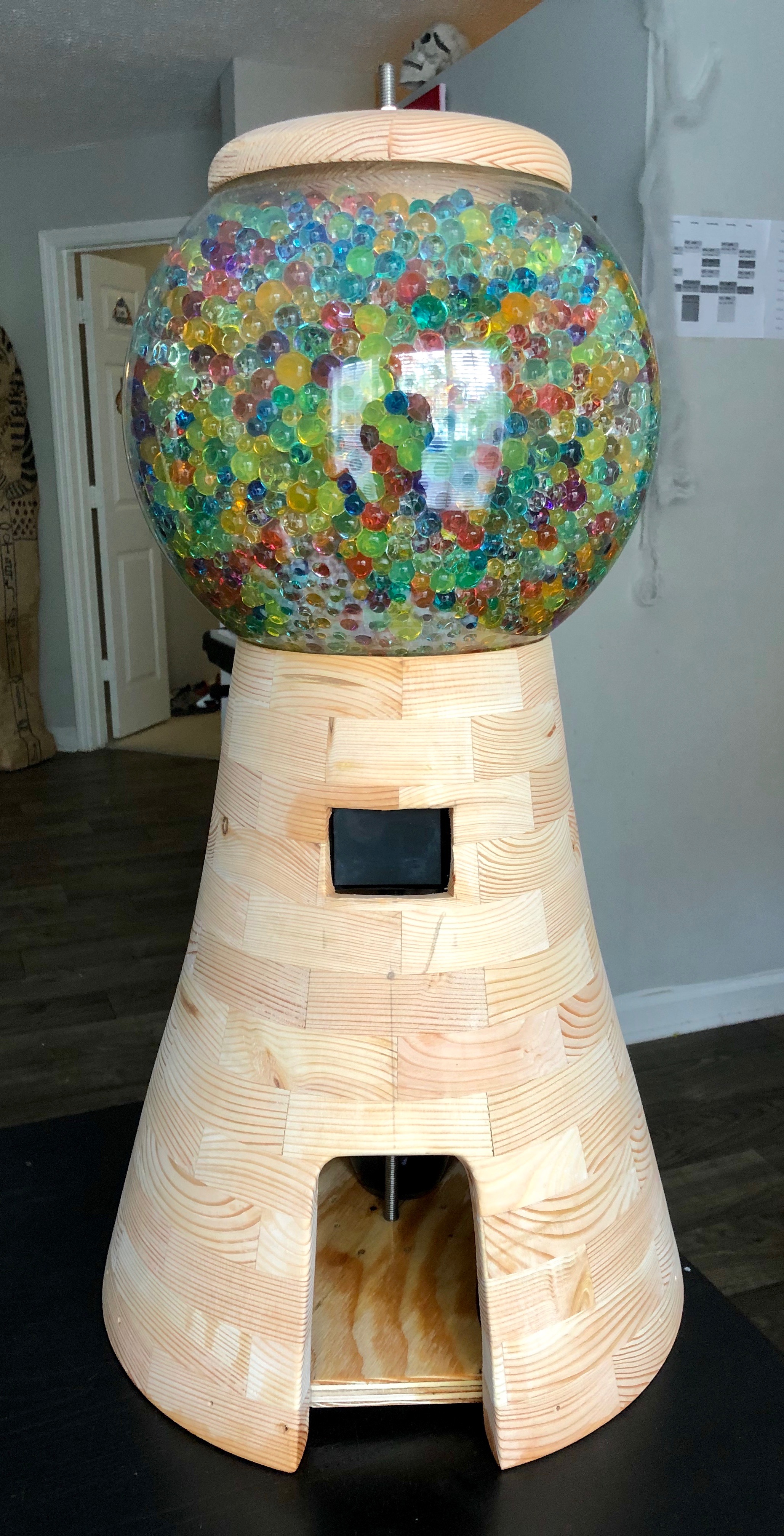
The idea of this project was to create an automated drink dispensing system centered around the mbed platform. This project is intended to be an interactive system that mixes and dispenses internally stored drinks. We wanted the system to resemble a gumball machine to give it a nice aesthetic and charm.
We decided to make the system gravity-fed for the sake of simplicity with the drinks being stored in a sphere at the top. The drinks would then be dispensed via solenoid control valves into a cup at the base of the system. The user interface to the system would be a TFT LCD touchscreen that a user can use to select the drink of their choice.
We also considered the use of peristaltic pumps for better liquid dispensing, a liquid flow meter for better liquid measurement, and a rotary encoder as an alternate user interface. However, peristaltic pumps are costly (~$25 each), the flow meter was incredibly bulky and could not fit within the system, and the rotary encoder made for a confusing hybrid UI so we removed it as well.
The mechanical system consists of the following components:
- Handmade wooden body and lid
- 1ft Acrylic Sphere
- Assorted Color Water Beads
- 3ft Threaded Steel Dowel
- 2x Hex Nuts
- 2x Washers
- 4x Condiment Bottles
- 4x 12V Solenoid Valves (food-safe)
- Assorted Push-Fit Connecters and Fittings
- 10ft, 1/4" OD Polyethylene Tubing (food-safe)
The electrical system consists of the following components:
- Custom Printed Circuit Board:
- mbed Microcontroller
- 5V Linear Voltage Regulator
- 3.3uF Ceramic Capacitor
- 1.0uF Ceramic Capacitor
- 4x 100 Ohm 1/4W Resistors
- 4x 4.7k Ohm 1/4W Resistors
- 4x 1N4001 Diodes
- 4x N-Channel MOSFETs
- Assorted 0.1" Male Headers
- 2.8in TFT LCD
- Flow Meter (Removed in final design)
- Rotary Encoder (Removed in final design)
- 12V, 2A Power Supply
- Barrel Jack
- Rocker Switch
This system relies on using Adafruit's TFT LCD touchscreen on the mbed. However, all of Adafruit's accompanying libraries and software support are made exclusively for Arduino (or Arduino-compatible) products. As a result, the first major step in the software development of this project was porting the necessary Arduino libraries to the mbed. The first library that we ported to mbed was Adafruit's GFX Library to provide us with a familiar graphics API. The second library we ported was Adafruit's ILI9341 Library for interfacing with the LCD. The third library we ported was Adafruit's FT6206 Library for interfacing with the FT6206 capacitive touch controller on the touchscreen.
Next, we wrote several test programs for testing the functionality of our hardware. We wrote (and also used some existing) test programs for both the Arduino (before porting the libraries to mbed) and the mbed. The Arduino test programs included a rotary encoder test, a flow meter test, and a couple LCD tests. The mbed test programs included a flow sensor test and several LCD tests.
The final program that runs on the system is fairly straightforward. It features 4 digital outputs for controlling each solenoid valve via a MOSFET. There is also a touch controller and an LCD object for touchscreen I/O. Finally a 2D array in program memory stores the hardcoded recipes for each drink. The rows of the array correspond to recipes and the columns correspond to the proportion of each mixer in the drink.
The main loop body initializes all the peripherals as needed and sets up an interrupt routine for when a user touches the display. If the user has selected an on-screen button corresponding to a drink, then the system dispenses the drink according to its recipe. The dispensing routine starts a timer and opens the appropriate valves for durations that are directly proportional to the ratios provided in the recipe. The scaling factor (called TIME_SCALAR) must be calibrated based on the flow of drinks through the system
The wooden body of the system was made by cutting several carefully measured trapezoids out of 8ft 2x4s and arranging them into 13 octagonal rings of decreasing size. The rings were then glued together and stacked to form a conical structure. This was then fastened to a lathe and turned down to the final shape of the system. Cutouts were then made for the touchscreen and the cup hole. The lid of the system was also turned on a lathe as well.
The acrylic sphere had five holes drilled in it (one for structural support and 4 for tubing) and situated on top of the system. The condiment bottles had holes drilled in their bases and had tubing fed in through the bottom and sealed with a combination of FDA-approved silicone sealant and hot glue. The condiment bottles were placed in the sphere with the tubing passing through the previously mentioned holes and the lid was placed on top. The threaded steel rod was cut to about 30" and fed through the lid, sphere, and bottom faceplate to serve as a central support column for the system, secured by a nut and washer on either side.
The tubing assembly of the system consisted of the 4 solenoids connecting to the condiment bottles on one side. On the other side, the solenoids connected to a set of Y-connectors to merge the 4 tubes into one for the output nozzle. This tubing assembly was secured to the inside of the wooden body using hot glue.
The electrical system consisted primarily of a PCB. The PCB took a 12V input for power and an onboard linear regulator to step the power down to 5V for the LCD and flow meter (which was later removed). The PCB featured 4 driver sub-circuits to allow the mbed to open and close the solenoid valves (which used 12V power) via a DigitalOut pin. The driver sub-circuits consisted of an N-channel MOSFET, a gate drive resistor, a gate pulldown resistor, and a fly-back diode. The PCB connected touchscreen, the driver sub-circuits, the rotary encoder (removed), and the flow meter (removed) all to the appropriate mbed ports. The PCB and touchscreen were mounted inside the body of the system using hot glue.
We'd like to thank the PI's of the Invention Studio for all their help on this project and for providing us access to their incredible facilities for wood-working, metal-working, soldering, and PCB manufacturing. We'd especially like to thank Morgan Cook, the Invention Studio's Director of Operations, for his continued help and support.