Is it possible to build a full EchoLink® node using a $6 microcontroller? I'm not completely sure, but let's find out. The goal of this project is to create the smallest, cheapest way to put a radio onto the EchoLink network. If you are new to the world of EchoLink please see the official website for complete information. EchoLink is a peer-to-peer VoIP (voice over IP) network used to link amateur radio stations across the Internet.
There are much easier ways to get onto EchoLink. The MicroLink project will only be interesting to someone who wants to get deep into the nuts-and-bolts of EchoLink/VoIP technology. In fact, you should start to question the sanity of anyone who spends this much time building their own EchoLink station. I am a homebrew enthusiast and I try to avoid off-the-shelf software/components where possible. This has been a huge learning opportunity.
The system currently runs on a Pi Pico W (RP204, ARM Cortex M0) board. I'm pretty sure it could also run on an ESP-32, or possibly an Arduino of sufficient caliber. More experimentation is needed here.
The software is fully open source. Now that EchoLink is "open," others can experiment with this important amateur radio technology. I am currently working on adding support for AllStarLink. More to follow ...
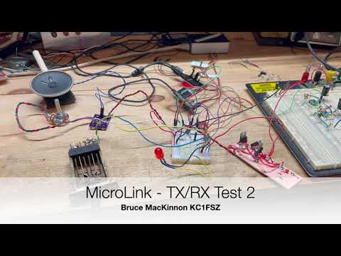
Here's my production setup at the moment. This station provides EchoLink access to the Wellesley Amateur Radio Society repeater (W1TKZ-L):

Note that there are no other computers required. The only things not shown in this picture are the 12V power supply, the antenna (on the roof), and the home WIFI network that the Pico W is connected to. The red LED is the 12V power indicator and the blue LED is the internet connection status.
Here's a demo video I made of the first bench test:
The microphone/analog section still needs some work.
Here's what it sounds like over the air:

The official PC-based EchoLink client written by Jonathan Taylor (K1RFD) is excellent and is the quickest/easiest way to get on EchoLink. Download it here. There are also versions that run on mobile phones. MicroLink is not a supported part of the EchoLink family of products.
I've learned many things about EchoLink during this project. One thing is for sure: Jonathan (K1RFD) who created the EchoLink system is an outstanding engineer and we should all be greatly appreciative of the work that he and the rest of the EchoLink team do on behalf of the amateur radio community. Thanks to Jonathan for his suggestions/advice along the way.
Huge thanks go to Steve Kondo (K1STK) for providing the mechanical design work for this project.
Thanks also to Julius Jones (W2IHY), creator of the world-famous EQPlus and other sophisticated audio gear, for his advice on the audio circuit.
I have a few extra boards which I would be willing to sell for a reasonable price if someone wanted to try to build a station of their own.
I am good in QRZ at KC1FSZ if you have any questions or suggestions. Or e-mail at bruce at mackinnon dot com.
My goal was to build a complete station from scratch, with no strings attached to PCs/servers.
I have made a PCB for ease of use with radios (link mode) and/or direct integration with repeaters. Further refinements of the PCB are in process.
This project required an in-depth examination of how the EchoLink protocol works. The notes I created during this analysis are located here.
- The main processor is a Pi Pico W (RP2040) development board. This includes WIFI connectivity. $6.00 on DigiKey.
- A 4G cellular data option is available using a SIM7600 module. (Not fully working yet.)
- Audio output generation uses the MicroChip MCP4725 I2C digital-to-analog converter. $1.27 on DigiKey.
- Audio input sampling uses the integrated ADC in the RP2040.
- Isolation transformers and optocouplers are used to eliminate the need for common ground between the radio and the MicroLink system. This helps to reduce digital noise.
- The radio link is an AZDEN PCS-6000H mobile rig.
- When not using the radio:
- Audio amplification uses the LM4862M 825mW amplifier. $2.23 on DigiKey.
- The local T/R key is from Federal Telephone and Telegraph Company (Buffalo, NY), made in 1920. Priceless.
- The microphone is an electret condenser with a LVM321 pre-amp and low-pass anti-aliasing filter. The microphone part needs work. The next revision will use a TLV9161 op amp for the microphone pre-amp to reduce noise.
Here's a picture of the the current version of the PCB.

This is a picture of the cellular module. This has passed some initial tests, but is not ready for production yet.

- The main station firmware is completely homebrew (C++, see GitHub repo).
- The LwIP embedded TCP/IP stack is used for IP connectivity on the Pi Pico W.
- Importantly, audio compression/decompression uses a GSM 06-10 Full Rate CODEC which is homebrew in C++. Getting that to work required studying the European Telecommunications Standards Institute specification for GSM and a lot of testing, but this was extremely interesting.
- I'm not using the Arduino development environment for this project. The toolchain is CMake/GCC/GDB using the Pico W SDK. I like this environment a lot. The firmware is flashed via SWD using openocd.
MicroLink identifies itself using a version string of 0.02MLZ.
Microphone Pre-Amp
Performance audio circuits are not my forte. The quality is improving with each iteration. This is what I built originally, but a new version using parts with better noise specs is in the works.

The microphone part will not be used when the radio is integrated. I will probably leave the speaker/amplifier in for monitoring purposes.
Audio Input
This is the circuit used when connecting directly to a radio's AF output (i.e. no microphone). This repeats some of the circuit shown above (but minus the high gain). This also shows the circuit used for carrier detect (COS). The idea is to boost up the rig's audio output (U6) and then compare it to an adjustable threshold (U8). There is no debounce in the analog part of the COS circuit - that is all done in software.

Audio Output
This is a work in process. The performance on the low end of the audio spectrum is not good yet.

I have a working version of the MicroLink system using 4G cellular internet
connectivity using an SIM7600A cellular module. The $70 USD breakout
board for this module comes from Waveshare and is linked here.
The Waveshare module was originally designed to plug into a full Raspberry Pi (NOT A PICO!), hence the
use of the term "hat," but it is possible to use the module directly via a serial
interface and there is no technical requirement to connect it to a Raspberry Pi.
I am communicating with the module using their AT command set across a 115,200 baud serial link. This requires a pretty elaborate state machine to allow bi-directional UDP traffic across a protocol that was originally designed so support auto-dialing modems. The Hayes people would be shocked if they saw what people were doing with AT commands. I've had good luck getting the SIM7600 to maintain the UDP data rate needed to support EchoLink.
I am using a pre-paid SIM card from Mint Mobile. It turns out that not all cellular providers support the "raw" SIM7600 module. In fact, it took a few conversations with their help desk to get them to activate my SIM card. The Mint Mobile activation website wants you to select what kind of phone you have (i.e. iPhone, Android, etc.) and apparently "homebrew EchoLink station" isn't a valid choice in their system yet. Someday ... But after some back-and-forth, they activated my SIM and within 30 seconds the "link" LED started flashing and I was on the Internet!
The only bad thing about Mint Mobile is that they don't appear to allow inbound UDP traffic into this module. Or at least I've not figured that out yet. ARRGG! This required the use of a TCP proxy to handle the traffic in/out of the cellular module. I've not documented this part yet because I am still hoping to eliminate this component.
Mint Mobile is an example of what is called a "Mobile Virtual Network Operator," or MVNO for short. The real mobile cellular infrastructure is built/run by Verizon, T-Mobile (including the remnants of Sprint), AT&T, and US Cellular. All of the other low-cost "providers" are essentially renting bandwidth from the big firms. In the case of Mint Mobile, they are using the T-Mobile network.
One interesting facet of the MVMO service is that the traffic is de-prioritized vs. the "real" carrier's traffic. So during congested times you might find that T-Mobile service is better than Mint Mobile's. You get what you pay for.
The mechanics of the prioritization is managed through the assignment of QCI levels. According to one article I saw, T-Mobile uses QCI 6, 7, 8, and 9 for their normal consumer plans. The lower numbers have higher priority. T-Mobile uses 6 (the best) for their "real" customers (i.e. pre-paid subscribers) and 7 for Mint Mobile. Interestingly, T-Mobile branded hot-spots run on level 9 (the worst).
MicroLink will update its internal time using an NTP server. The main value of this is to ensure that the timestamps on the internal log messages are correct.
The SNTP message protocol is quite simple. The request is 68 bytes, mostly zeros. The non-zero bytes are as follows:
- Byte 0: (binary) 00 100 011. This denotes an SNTPv4 client request.
- Byte 1: zero
- Byte 2: 6
- Byte 3: 0xec
- Bytes 12-15: (ascii) UKNO
- Bytes 40-43: The client's current time in seconds since the Epoch, big endian format.
The response that comes back has been observed to be around 52 bytes, although this may vary in some situations. The important information in the response is:
- Byte 0: (binary) 00 100 100. This denotes an SNTPv4 server response.
- Bytes 40-43: The server's current time in seconds since the Epoch, big endian format.
Steve K1STK designed and fabricated a great enclosure on his 3D printer. Here's what the PCB looks like with the case:

- The standard audio sample rate for GSM-FR/EchoLink is 8 kHz at 12-bits of resolution.
- The audio CODEC creates/consumes one 640 byte packet every 80ms. One of these packets is moved 12.5 times per second.
- It takes the RP2040 about 3ms to decode a 33 byte GSM frame into PCM.
- It takes the RP2040 about 7ms to encode a 160 sample PCM frame into GSM.
- The UDP data rate needed to sustain audio quality is approximately 14,000 baud.
- The RP2040 runs at 125 MHz. Only one of the two processors is used at this time.
- The DAC runs on an I2C bus running at 400 kHz.
- The voice prompts (all letters, numbers, and a few words) take up about 40K of flash. The audio is stored in GSM full-rate format for efficiency.
- Current flash size (used) is ~650,000 bytes.
- The RP2040 communicates with the SIM7600 4G cellular module at 115,200 baud. This is about 10x the theoretically-required bandwidth to maintain a single channel.
(More detail to follow)
reboot
status
log
tone
dropall
add [callsign]
drop [callsign]
Configuration commands - using during initial setup:
set addressingserver [EchoLink addressing server hostname: ex: naeast.echolink.org]
set callsign [your call]
set password [your password]
set fullname "[your full name]"
set location "[your location]"
set wifissid "[yourssid]"
set wifipassword [your password]
set hardcos [0 or 1.  Enables or disables hardware carrier detect. Defaults to 0.]
set coson [COS debounce ms during off->on transition. Defaults to 10.]
set cosoff [COS debounce ms during on->off transition.  Defaults to 400.]
set costhreshold [noise power floor used to decide when COS is detected]
set adcoffset [value that is added to the raw ADC value.  Used to center the DC bais at 2048.]
I implemented my own fixed-point audio compression/decompression CODEC for the GSM 0610 Full Rate protocol by following the specification here. The coding scheme is the so-called Regular Pulse Excitation - Long Term prediction - Linear Predictive Coder, generally referred to as "RPE-LTP." This standard was developed as part of the modernization of the European mobile phone system in the late 1990s and is a good balance between efficiency, quality, and compactness.
The European Telecommunications Standards Institute (ETSI) publishes a comprehensive set of test vectors containing known audio streams (PCM) and the corresponding GSM encoding. I have used that test data to validate that my CODEC is 100% complaint.
The smallest/cheapest microcontrollers lack hardware support for floating-point, so I built my CODEC using fixed point (Q15) math.
One of the most difficult challenges I had with this project was getting audio that was "smooth" in both directions. This stuff is probably obvious to people who are well versed in the state-of-the-art of VoIP. Here are a few points that will help anyone getting into this.
- Accurate/consistent clocking of the audio chain is essential. GSM uses an 8 kHz clock, which means we need an audio sample once every 125 microseconds. I know this seems hard to believe, but inconsistencies in this clock can be "heard." This is where hardware timers with efficient interrupt service architectures are important. The highest priority activity of the microcontroller should be the creation/consumption of an audio sample every 125 uS exactly - everything else in the system has some leeway.
- An EchoLink receiver gets an audio packet approximately every 80 ms. Each packet contains 4 frames that each represent exactly 20 ms of audio. Finally, each frame contains 160 samples which each represent exactly 125 uS of audio. From point #1 above, we already know that the timing of the 160 samples within each frame is critical. However, we also need ensure that the 20 ms frames are played continuously without the slightest gap between them. This gets into an interesting problem because the frames are streaming across the busy internet (not to mention low-cost WIFI hardware) and may be subject to small timing inconsistencies. There is simply no way to ensure that an EchoLink packet will arrive every 80 ms. Sometimes the gap might be 81 ms, sometimes 79 ms, etc. This variability is known as "jitter" and it is a common issue in VoIP systems. The fix is simple: we need to delay/buffer the audio generation in the receiver slightly to give ourselves a margin of error to accumulate packets. The MicroLink system keeps a buffer of 16 audio packets and holds back the start of audio generation (after squelch break) until the buffer is half full. This means that the receive path is delayed by around 8 x 80 ms above and beyond any delay in the Internet itself. Experimental work is ongoing to make this adaptive so that the delay is minimized. Of course if the buffer empties out (i.e. several slow packets in a row), all bets are off.
- A MicroLink node can have up to four "remote" (i.e. internet based) stations connected at the same time. This of this as a mini-conference. In the extreme case (four users connected), the inbound audio packets from the station who is speaking need to be routed back out to the other three listening stations AND be sent to the CODEC/DAC for local radio transmission. Since the CODEC is relatively time-consuming, it is important to reflect the audio packets back out onto the internet to the listening stations before dealing with the GSM decode needed for the local radio link. This will ensure maximum parallelism and smooth audio for all stations involved.
Two important things that make a difference for audio noise performance. Note that these comments are relevant when using the Pi Pico board as-is. The rules will be different if using the RP2040 chip directly.
Per Pico datasheet:
For much improved ADC performance, an external 3.0V shunt reference, such as LM4040, can be connected from the ADC_VREF pin to ground. Note that if doing this the ADC range is limited to 0-3.0V signals (rather than 0-3.3V), and the shunt reference will draw continuous current through the 200Ω filter resistor (3.3V-3.0V)/200 = ~1.5mA.
Per Pico datasheet:
AGND is the ground reference for GPIO26-29, there is a separate analog ground plane running under these signals and terminating at this pin. If the ADC is not used or ADC performance is not critical, this pin can be connected to digital ground.
When using MicroLink as a bridge to a repeater system via a radio link, be careful about the duty cycle limitations of the bridge radio you are using. The W1TKZ-L system uses an AZDEN mobile rig that certainly wasn't designed for 100% key down.
During "normal" repeater use this isn't a problem because the link radio is only keyed when a remote EchoLink user is speaking - that's no different from using the link radio directly. However, if more a complicated configuration is used (examples: linking two repeater systems together, joining a repeater to a conference server, etc.) things can become problematic if the link radio is required to be keyed constantly to transmit the activity happening on the "other" repeater or in the conference.
If you have a transmitter than can be keyed for long periods of time then this won't be an issue. But if not, the MicroLink system supports a configurable duty cycle limit (defaults to 50%). Once the link radio has been keyed for more than 50% of the time in any 5 minute interval the radio is un-keyed and allowed to rest.
This is the official binary that runs in production.
(These notes are not comprehensive yet.)
git clone https://github.com/brucemack/microlink.git
cd microlink
git submodule update --remote
mkdir build
cd build
export PICO_BUILD=1
cmake -DPICO_BOARD=pico_w ..
make link-main-2
openocd -f interface/raspberrypi-swd.cfg -f target/rp2040.cfg -c "program link-main-2.elf verify reset exit"
(These notes are not comprehensive yet.)
git clone https://github.com/brucemack/microlink.git
cd microlink
git submodule update --remote
mkdir build
cd build
cmake ..
make <target>
(No longer used)
esptool.py --chip auto --port /dev/ttyUSB0 --baud 115200 --before default_reset --after hard_reset write_flash -z --flash_mode dio --flash_freq 40m --flash_size 4MB 0x0 /home/bruce/Downloads/ESP32-WROOM-32-V3.2.0.0/factory/factory_WROOM-32.bin
# Used to receive UDP packets
netcat -u -l 5198
# Used to send UDP packets.  The printf command supports non-printable.
printf 'Hello\rWorld' | nc -u -w1 192.168.8.210 5198

# Login test
printf "lKC1FSZ\254\254xxx\rONLINE0.02MLZ(08:11)\rWellesley, MA USA\r" | nc -w 10 naeast.echolink.org 5200

# SIM7600 open TCP socket in transparent mode:
ATE0;+CIPMODE=1;+NETOPEN;+CIPOPEN=0,"TCP","54.89.121.215",8100
- 3.5mm Jack
- Tip - NC
- Ring - Rig mic in, MicroLink audio out
- Sleeve - PTT when pulled to ground
- 2.5mm Jack
- Tip - Rig speaker+ out, MicroLink audio in
- Ring - Rig ground
- Sleeve - Rig ground
This has been discussed at length in other venues. The method of detecting the receive carrier depends on the radio you are using. Unless you are willing to crack it open, there is no explicit carrier detect "signal" on the Baofeng HT. My integration with this rig just listens for noise on the audio output line and triggers accordingly. That seems to work just fine. See the schematic for details.
The RP2040 has no DAC and the MCP4725 is cheap and plentiful. This could certainly be done with a fancier audio CODEC, but we'll think about that later.
As mentioned previously, it is important to deliver audio very smoothly, and with as little CPU overhead as possible. To that end, we are leveraging the TX FIFO on the I2C channel to quickly write to the I2C bus without any blocking.
This is a bit tricky because there are two completely independent data formats that need to work together:
- The RP2040 I2C format (really the DW_apb_i2c format) that is manifest in the format of the IC_DATA_CMD register. Aside from the "normal" byte of data in this register, we have extra bits that control the START/STOP/RESTART cycles of the I2C bus. Each write to the I2C_DATA_CMD register contributes both data bits and control bits.
- THe MCP4725 I2C format. This is a 12-bit DAC, but it's not as simple as justing writing 12 bits to it. There are other control bits in the message being sent to the MCP4725 on the I2C bus and those need to be configured properly.
The DAC I2C writes are done inside of the same interrupt service routine that performs the ADC read. This interrupt is set to run at exactly 8kHZ by setting the ADC FIFO depth to 1. The ADC and DAC are both running constantly, regardless of whether the system is transmitting or receiving.
There are some different ways of using the I2C bus but we're using the simple way since speed is not a big issue. What we really care about is consistency. Each audio sample will be transmitted on the I2C bus using a normal START-address-data-STOP sequence. There are fancier things you can do on the I2C bus involving restarts but we don't need that for our audio bandwidth requirements.
The MCP4725 also provides some choices to improve efficiency. The "fast mode" described in section 6.1.1 of the datasheet allows you to perform continuous data writes without addressing cycles. We don't need that for the 8kHz application (at least I don't think we do).
In the "slow" mode, the MCP4725 needs the regular I2C address byte followed by three data bytes. Actually, the first of the three data bytes is more like a command byte from the perspective of the MCP4725. So the complete sequence will need to look like this:
- -> I2C START
- -> Address Byte (MCP4725 "first byte")
- <- I2C ACK
- -> Data Byte 0 (MCP4725 "second byte")
- <- I2C ACK
- -> Data Byte 1 (MCP4725 "third byte")
- <- I2C ACK
- -> Data Byte 2 (MCP4725 "fourth byte")
- <- I2C ACK
- -> I2C STOP
The START and STOP steps are commanded by bits in the RP2040 I2C_DATA_CMD word so they don't require distinct writes to the TX FIFO. Likewise, the address byte is generated automatically on start. In order to achieve the sequence above we'll need to make three distinct data writes into the I2C TX FIFO for each audio sample.
Combining the RP2040 datasheet figure 72 and the MCP4725 figure 6-2, we can determine that the three writes will look like this:
0 0 0 | 0   1   0   x   x   0   0   x
0 0 0 | d11 d10 d09 d08 d07 d06 d05 d04
0 1 0 | d03 d02 d01 d00 x   x   x   x
These writes are happening into the LSB end of the I2C_DATA_CMD register (i.e. data bits [10-0]). Bits [31-11] are not used and will be set to zero. The x's in the illustration above show where the MCP4725 has don't-cares. These will be set to zero.
The rules for DTMF are standardize by the International Telecommunications Union (ITU). The relevant standards documents are located here:
The most important details from the standards document:
- There are a total of 16 possible symbols. Each symbol is made up of two tones: one from the "low group" and one from the "high group."
- The "low group" frequencies are: 697, 770, 852, 941 Hz. These are on the rows of the keypad.
- The "high group" frequencies are: 1209, 1336, 1477, 1633 Hz. These are on the columns of the keypad.
- Even though the phone/radio keypad only has 3 columns, there is a an "extra" column in the spec for A/B/C/D.
- Transmission must be within 1.8% of frequency standard to be recognized. This means that the received frequency can be +/- 1.8% from expectation, or 3.6% wide.
- If we apply the 3.6% rule to the highest frequency, we get a resolution bandwidth of 58.788 Hz (1633 * 0.036).
- Distortion products (e.g. harmonics) must be -20dB below the fundamental.
- There are rules around the relative powers of the two tones that make up the symbol. In the US, the high group frequency power level may be up to 4 dB more or 8 dB less than the low group frequency power level for the symbol to be considered valid. In the TELCO lingo, this difference is known as "twist" and it is expressed in dB. Positive twist means that the higher frequency is louder.
- Timing requirements are as follows.
- A symbol must be transmitted for at least 40ms. Symbols shorter than 23ms must be rejected.
- The gap between symbols must be at least 40ms.
- 23ms is 184 samples at a sampling rate of 8 kHz. We will round this to 20ms (160 samples) since it is conveniently the same size as a GSM frame.
- 40ms is 320 samples at a sampling rate of 8 kHz
- A block of 136 samples is required to achieve 58.788 Hz resolution at a sampling rate of 8 kHz. If we use more than 136 samples then the resolution will become finer than 58 Hz and we'll need to compute the power in more than one bucket - so we don't want to do that.
- So for each 160 sample frame we will use the latest 136 samples and ignore the other 24. Close enough.
- We will look for symbols that last more than two 160 sample frames.
- We will look for noise periods that last more than two 160 sample frames to consider the symbol valid (i.e. the pause).
- Algorithm notes:
- For each 160 samples.
- Evaluate power at all 8 frequencies.
- Compare the power of all 16 pairs by summing powers at each intersection.
- Look to see if any pairs stand out by at least +20dB. If so, that is the candidate pair.
- Check the twist on the candidate pair to make sure it falls within the +4dB -> -8dB standard.
- Compute the harmonic power for both frequencies in the pair and make sure it falls below the -20dB standard.
- If all tests pass, then do the 40ms duration checks.
- The +4dB level is equivalent to x ~1.58 linear. Testing a/b > ~1.58 is the same as testing 4a/b > ~6.
- The +8dB level is equivalent to x ~2.5 linear. Testing a/b > ~2.5 is the same as testing 4a/b > ~10.
- Official EchoLink Site: https://www.echolink.org/
- Pi PICO Stuff
- Pi PICO W Stuff
- ESP-32
- SIM7600 Cellular Module
- SIM7600 module AT Command Reference: https://www.waveshare.net/w/upload/6/68/SIM7500_SIM7600_Series_AT_Command_Manual_V2.00.pdf
- SIM7600 module application notes: https://www.waveshare.com/w/upload/4/4b/A7600_Series_TCPIP_Applicati0n_Note_V1.00.pdf
- SIM7600 Hardware Design Guide
- The "hat" I am using
- Windows Audio Related:
- SNTP
- Components
- Rig Integration
- Analog/Audio
- DSP Related
- DTMF Related
- Other
- Analog Devices Filter Wizard
- https://www.purevpn.com/what-is-vpn/protocols/openvpn
- https://en.wikipedia.org/wiki/OpenVPN
- https://www.analog.com/media/en/technical-documentation/application-notes/an-1368.pdf
- Information about Ferite Beads from Altium.
- MD5 Implementation: https://www.cs.cmu.edu/~jcl/linux/seal/md5.c
- Audio Transformer: https://electronics.stackexchange.com/questions/648953/what-does-the-impedance-value-of-audio-transformers-specifically-mean-in-terms
- Very interesting audio processing stuff: https://www.repeater-builder.com/tech-info/audio-processing.html
- Ceramic vs Tantalum Capacitors in LDOs
- DB9 Connector
- 5.5mm power Connector