Home
Updates:
- Please note the below information might be outdated and better alternatives could be available.
- Build tip: Simply removing the TL072 op-amp from its socket, turns the stereo microphone amplifier into a regulated attenuator circuit. This can actually yield better sound quality (since the electret mics already have an integrated amplifier) so we advise removing the TL072.
- If you have a GoPro camera, click here for the simplified instructions.
Note: download files with "right click -> save as"
- 3D printed ear models: left (STL) & right (STL)
- Middle support: either laser cutted (DXF) or 3D printed (STL)
- Metal insert for the tripod (1/4" to 3/8" convert screw). You can find it in eBay
- x6 M3 screws, length 10mm
- x6 M3 nuts
- x1 3D printed potentiometer knob (STL)
- x1 Stereo microphone amplifier (Schematic, Layout, Photolith PDF, Gerber):
- x2 Electret microphone capsule (I used the POM-5238P-R but most will work)
- x1 Power switch
- x1 5mm LED diode
- x1 3.5mm Stereo jack connector
- Shielded stereo audio cable (1 meter)
- Thin & flexible stranded copper wire (spare pieces)
- 9V battery (please think of the environment and use rechargeable ones ^^)
- x1 1N4001 diode
- x1 TL072 operational amplifier
- x1 A100k dual potentiometer (eBay)
Resistors:
    x4 100k (or 75k)
    x3 13.7k (or 13k)
    x2 50 Ohm (or 51 Ohm)
Capacitors:
    x1 100nF
    x1 22uF
    x5 2.2uF
    x2 15pF
Required tools: Soldering iron, hot glue gun, screwdriver
The circuit we are about to build amplifies the signal from the microphone capsules into gain-controlled line level that can be plugged into a camera or other recording devices.
The circuit has been tested with the POM-5238P-R microphone capsules:
http://www.puiaudio.com/product-detail.aspx?categoryId=4&partnumber=POM-5238P-R
First step is to obtain the PCB. You can either etch it with the photolith (PDF), or mill it with the gerber and gcode files.

Then solder the components according to the following guide. Use the schematic or layout if you have any doubts.

Note: Remember to solder the power switch between the 9V battery connector and the amplifier circuit.
Lout, GND and Rout must be connected to the 3.5mm jack as follows:
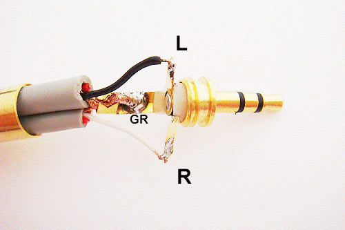 (
(
The POM-5238P-R microphone capsules have the polarity shown in the figure:

After soldering all the wires, the result will look like this:

The wires have been glued in place to minimize strain in the connections.
Now you can add the tripod metal insert (eBay) into the 3D printed ear support:

Assembly tip: You can use a soldering iron to heat the part and screw it very tightly into the plastic.
Next you need to screw in the power switch and glue the microphones in place. I've used a hot-glue gun, if you do, make sure the microphones are not obstructed by the glue!!


Finally you can screw the potentiometer in place, that will hold the electronic board without glue.
 The battery connector is glued to the wooden support.
 You can use some more glue to fix the main audio wire.

You did it! Congratulations!! :D Now you can plug it into the "line in" connector in your computer and record super cool binaural audio (we recommend the free software Audacity).
 Please send me pictures of your build! I'd love to see it!! :-)
There is a simple way to use the microphones without the amplifier circuit, plugging them into the GoPro USB-mini connector:


Pictures by Philippe Benaim (Thank you!!!).
Author: Carlos Garcia Saura License: CC-BY-SA (http://creativecommons.org/licenses/by-sa/4.0/)