Today felt like a day for tinkering! I’ve been playing around with a bunch of different Microprocessors and Developer boards in the last few week and I’ve come to like the Heltec Wifi Kit 32 a lot. It has been around for a while and there are quite a few examples of other projects out there but, I didn’t see this specific setup or at least not in a real working version. The nice thing is that the board has a build in SSD1306 OLED display.
The hardware setup I am going to play with today is fairly basic, the Heltec Dev Board, a Bosch BME680 sensor module, a DHT22 sensor module, a breadboard and a few wires.
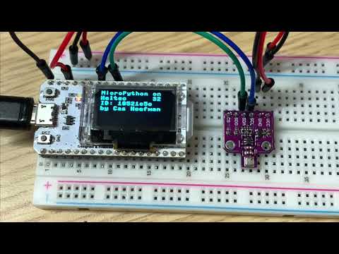
If you are going to follow along with my, once it is all hooked up and programmed it will look something like this:
The software setup is also pretty simple, a Raspberry Pi 4B as a development computer running the basic Raspberry Pi OS with desktop. I’ve been playing around with Microsoft’s Visual Studio Code for Raspberry Pi a bit lately so I will use that as my development environment.
The BME680 Sensor Kit to Dev Board connection has some interesting parts to it. I am planning on using I2C to connect the sensor to the dev board but as you can see in the pinout diagram for the dev board, the SCL and SDA pins are also used by the OLED display. And, I want to also use the display to display the data that we are going read from the sensor. But, that isn’t an issue you can use both at the same time. (The Sensor Kit also support SPI but I’ll leave that for another time. You can read a little more about the difference between I2C and SPI here.)
So to get this all hooked up properly you connect:
- GND from the Dev Board to GND on the BME 680 Sensor Module & the DHT22 Sensor Module
- 3.3V from the Dev Board to VCC on the BME680 Sensor Module & the DHT22 Sensor Module
- Pin 15/GPIO15/OLED_SCL on the Dev Board to SCL on BME 680 Sensor Module
- Pin 4/GPIO4/OLED_SPA on the Dev Board to SDA on the BME 680 Sensor Module
- Pin 13/GPIO13 on the Dev Board to the DHT22 Sensor Module
At some point I might add a proper diagram instead of the image but this is what it looks like right now with either a Heltec Wifi Kit 32 and a Heltec LoRa 32 V2.

And here is a Fritzing version of it.

Next we have to get the Heltec Dev Board setup properly so it will run Micropython. To get that setup we need to install a few things on the Raspberry Pi (or your MacBook for generic Linux machine).
To flash the board we are going to need ESPTOOL and AMPY. To install that you can just run.
pip install esptool adafruit-ampy rsa
Once you do the you can now connect to the board. Plug in a USB cable and just hook the board up to a USB port on your computer. We now need to figure out what USB port this this thing is connected to, you do that with:
ls /dev/ | grep -i "tty" | grep -i "usb"
export SERIALPORT="/dev/ttyUSB0"
Depending on your setup you will get a different output from the first command, on a Mac for example that could be /dev/tty.usbserial-0001 or something similar! Just update it accordingly.
You can test the connection to the board by running:
esptool.py --port $SERIALPORT flash_id
Next you are going to have to download the Micropython Firmware for the Generic ESP32 module Binary from the Micropython website. I used “esp32-idf4-20200902-v1.13.bin” but by the time you read this there might be some newer version. So use your best judgement!
Once you have that downloaded your are going to erase the board and flash the new firmware, to do that rung the following two commands:
esptool.py --chip esp32 --port $SERIALPORT erase_flash
esptool.py --chip esp32 --port $SERIALPORT --baud 460800 write_flash -z 0x1000 ~/Downloads/esp32-idf4-20200902-v1.13.bin
Now you have a Heltec Wifi Kit 32 running Micropython, congrats! You can connect to the device by running:
screen -L $SERIALPORT 115200
Note that the connection to the board is a little finicky. If it doesn’t connect, disconnect the thing from the USB port and try it again. And if you get a blank screen, try pressing enter to get to the command prompt for the board. Once you are connected you can press the RST button the on the device again and you will see the board boot up again, you will not loose the connection when you do that.
Once that is done you are ready to upload some code to the board. You are going to need to upload 4 files.
bme680.py this is what main.py is going to use to get the reading from the BME680 sensor.
ssd1306.py this is what main.py uses to display stuff on the OLED display.
config.py is not really necessary but a good practice, this file hold configuration settings that the main.py is going to use. Open this file and edit the wifi settings so it matches your wifi network. If you are using a different ESP32 board you might also need to change the led_pin otherwise your board might not work properly.
config.py
device_config = {
 'led_pin': 25
}
wifi_config = {
    'ssid':'<WIFISSID>',
    'password':'<WIFIPASSWORD>'
  }
main.py this is the “program” that runs on the board, connects to Wifi, gets the current GMT date and time, reads the sensor and prints all the data to the OLED display.
To flash all these files to the boar you just run:
ampy --port $SERIALPORT --baud 115200 put ssd1306.py
ampy --port $SERIALPORT --baud 115200 put config.py
ampy --port $SERIALPORT --baud 115200 put main.py
ampy --port $SERIALPORT --baud 115200 put bme680.py
Once you do that disconnect the board from your computer, connect it again and run:
screen -L $SERIALPORT 115200
The display of the Dev Board will light up and display some setup information first and then will display the sensor readings.