

The Neopixel LED module has many attractive features. With a microcontroller base, they can produce millions of different lights. In this tutorial, we are going to change the status of the neopixel LED according to the required colors with the help of the rotary encoder module and Arduino board. In this way, by changing the rotary angle of the encoder in each step, the status of the neopixel LED will also change.
- Choose Neopixel Colors
- Define Diffrent Modes
In the neopixel LED control project, by specifying the values of R, G, and B in the project code, the neopixel status will change by moving each step of the rotary encoder module. In this way, each step of the encoder represents a case in the project code. Each case comes with certain values, which are displayed by changing the status of the encoder.
- Arduino Nano
- Rotary Encoder
- Neopixel LED
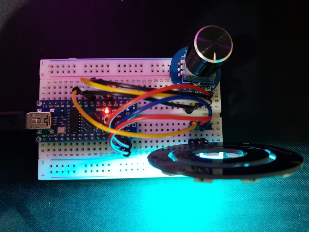
Pins 2 on the Arduino connect to S1 and S2 on the rotary encoder. Also, pin 4 on the Arduino connects to the input of the rotary switch. Then pin 6 on the Arduino connects to the neopixel data input. Both modules are powered by 5 volts.
- Encoder and Arduino
| Arduino | Encoder |
|---|---|
| 4 | Key |
| 2 | S1 |
| 3 | S2 |
| Vin | 5v |
| GND | GND |
- Neopixel and Arduino
| Arduino | Neopixel |
|---|---|
| 6 | Din |
| Vin | 5v |
| GND | GND |
- Complete Schematic

using neopixel ring modules and a rotary encoder as well as an Arduino nano board, we created and displayed different modes with neopixels, but you can also change the created modes according to the need.
Distributed under the MIT License. See LICENSE.txt for more information.
CiferTech - @twitter - CiferTech@gmali.com
Project Link: https://github.com/cifertech/Encoder_Neopixel