NOTE: the MIT license of this repo means all individual resources made by myself, the content of the tutorial and the example codes is licensed under MIT. All third-party opensource projects, upstream source codes and patches to other opensource projects will/should follow their own LICENSE.
NOTE2: ATMEL was aquired by MicroChip in 2016, and MicroChip is not friendly to opensource. It may not affect AVR echo-system, but you should know it.
AVR is a family of modified Harvard architecture 8-bit RISC microcontrollers, it was developed in the year 1996 by Atmel Corporation and acquired by Microchip Technology in 2016.
The architecture of AVR was developed by Alf-Egil Bogen and Vegard Wollan. AVR derives its name from its developers and stands for Alf-Egil Bogen Vegard Wollan RISC microcontroller, also known as Advanced Virtual RISC. The AT90S8515 was the first microcontroller which was based on AVR architecture.
AVR microcontrollers are available in three categories:
- TinyAVR – Less memory, small size, suitable only for simpler applications
- MegaAVR – These are the most popular ones having good amount of memory (upto 256 KB), higher number of inbuilt peripherals and suitable for moderate to complex applications.
- AVR Dx – The AVR Dx family is featuring multiple microcontroller series, focused on HCI, analog signal conditioning and functional safety.
- XmegaAVR – Used commercially for complex applications, which require large program memory and high speed.
For more info about AVR, please refer to https://en.wikipedia.org/wiki/AVR_microcontrollers.
Maybe the most famous development board using AVR is Arduino. Arduino is an AVR processor running special code that lets you use the Arduino environment to program and upload code easily. This tutorial is not for Arduino development, it's for AVR opensource toolchain.
- Hardware prerequist
- Toolchain overview
- Compiler and SDK
- Programming
- Debugging
- how to make a debugwire FUSE rescue board
- how to make your own HV Serial UPDI programer
- how to update USBASP firmware
-
AVR development board:
- This tutorial will use various models of AVR include atmega128(ISP and JTAG)、atmega328p(Arduino nano)、attiny13/85(ISP and debugwire)、attiny806(UPDI) and atmega4808/4809(UPDI), etc.
-
Programmer:
- ISP Programmer (either usbasp or usbtiny)
- Or an arduino uno/nano board (which can be turned to a ISP programer)
- Or CH340 serial adatper with a self-made adapter to support programming with debugwire/UPDI.
- [Optional] Or High voltage debugwire and UPDI programmer to rescue your “bricked” device (you can make them yourself).
- Or All debuggers mentioned below.
-
Debugger:
- AVR JTAG ICE and above for JTAG (only about 10 of the oldest model of AVR has JTAG support, such as M128)
- or AVR JTAG ICE MKII and above for JTAG/debugwire
- or AVR JTAG ICE 3 / ATMEL ICE / PICKIT4 for all debugging protocol include UPDI
- or CH340 serial USB adapter with a self-made 4.7k adapter for dwdebug. and this is the only complete opensource(include hardware and software) debugging solution for AVR.
Due to the complicated situation,Here is some notes for beginners:
NOTE:
-
You'd better have an ISP programmer to program or change the FUSE bits.
-
Not all arduino but most of them are AVR board and suite for this tutorial. Arduino uno/nano have a USB bootloader to make programming easy (no additional hardwire adapter required to program) and can be turnned to a ISP programmer. that's to say, if you already have an arduino board, it's not necessary to buy a new ISP programmer.
-
Arduino uno/nano are lack of debugging support due to circuit design related to RESET pin, you need modify the hardware to enable it (and do not do that).
-
Changing FUSE bits is a little bit dangerous for beginners, it may 'brick' a device. For example, any ISP programmer is able to program DWEN debugwire FUSE bit. but if you want to unprogram it, you have to use AVR DRAGON and above devices, or you have a High-Voltage programmer. For UPDI, if you set the UPDI pin as GPIO, you have to use HV UPDI programmer to unprogram it. please refer to the section "how to make a debugwire FUSE rescue board" and "how to make your own HV UPDI programer".
-
There are various programming/debugging prototols for different AVR models, such as ISP, JTAG/debugwire/PDI/UPDI, etc. Earlier version of ICE devices may lack of support for some protocols,The latest official ATMEL-ICE is always the best choice except the price. And all debugging protocol from ATMEL or MicroChip are close source and undocumented, you should know that, the only exception is debugwire, it had complete opensource hardware and software support.
-
PICKIT-4 supports all AVR debug protocols include HV UPDI support (which is not supported by ATMEL-ICE), but lack of good opensource support except avadude and pymcuprog for avr mode. It's not necessary to buy a very-expensive PICKIT-4 if you only need to program AVR.
-
There is no opensource hardware/firmware which can support UPDI debugging up to now, you have to buy a commercial debugger such as ATMEL-ICE.
- Compiler: avr-gcc
- SDK: avr-libc
- Programer: avrdude/dwdebug/pyupdi/pymcuprog
- Debugger: avarice/dwdebug/bloom and avr-gdb
- [optional]Simulator: simavr.
AVR has very good support from opensource community, the opensource toolchain consists of avr-binutils(binary utilities), avr-gcc(compiler), avr-libc(c libraries), avrdude(the programmer), avarice(the debug bridge) and avr-gdb(the debugger). it's not necessary to build the toolchain yourself, since almost every linux distribution shipped these packages, just install them with pkg management tools of your distribution.
If you want to find a prebuilt toolchain, the AVR toolchain from Arduino IDE (located at <arduino ide dir>/hardware/tools/avr/) is the best choice.
As usual, let's start with a blink example, below codes is well self-explained:
// main.c
// blink led every second
// wire: PB0->Resistor-> LED->GND
// for Arduino user: PB0 is the 'D8' pin.

#include <avr/io.h>

#ifndef F_CPU
#define F_CPU 8000000UL // change F_CPU according to clock speed, used by delay.h
#endif
#include <util/delay.h>

// 1 sec if F_CPU set up correctly.
#define MS_DELAY 1000

int main (void) {

    DDRB |= 0x01;// PB0 as OUTPUT

    PORTB &= 0xFE; // PB0 to 0

    while(1) {
        PORTB ^= 0x01; // toggle PB0
        _delay_ms(MS_DELAY);
    }
}
Save it to 'main.c' and build:
avr-gcc -c -g -Os -mmcu=<MCU TYPE> main.c -o main.o
avr-gcc -mmcu=<MCU TYPE>  main.o -o main.elf
avr-objcopy -O ihex main.elf main.hex
You should change the <MCU TYPE> according to your board. for mcu type avr-gcc already supported, please refer to: https://gcc.gnu.org/onlinedocs/gcc/AVR-Options.html.
The blink example in this repo provide a configurable 'Makefile', you can change the 'MCU_TYPE' defined in 'Makefile'.
NOTE: there is a lot of tutotial use -R .eeprom with avr-objcopy, it's meaningless for this example.
After 'main.hex' generated, there are various way to program 'main.hex' to AVR MCU. it depend on which protocol your AVR MCU supported and which adapter you use.
As mentioned above, the software we mostly used to program AVR MCU is avrdude, it supports almost all AVR programmers, and can directly program Arduino with arduino bsl. The common usage of avrdude looks like as below.
To detect target MCU:
sudo avrdude -c <programmer> -p <target>
If you use AVR Dragon/JTAG ICE MKxx/ATMEL-ICE, you may need to supply power to target device seperately.
To program target MCU:
sudo avrdude -c <programmer> -p <target> -U flash:w:<hex file>
The <programer> can be:
- usbasp
- usbtiny
- atmelice_isp/atmelice_dw/atmelice_pdi/atmelice_updi for ATMEL-ICE
- arduino
- jtag2updi
The <target> can be:
- m128 for atmega128
- m328p for atmega328p (Arduino uno/nano)
- t13 for attiny13
- t85 for attiny85
- t816 for attiny816
- m4808 for atmega4808 (Thinary nano 4808)
- m4809 for atmega4809 (Arduino nano every)
For all programmers and targets 'avrdude' can support, try run:
sudo avrdude -c help
sudo avrdude -p help
If you want to use jtag2updi or HV jtag2updi programmer to program a UPDI target, you need to update avrdude to 7.0, or need a modified avrdude.conf which can be found in https://github.com/ElTangas/jtag2updi.
for avrdude < 7.0:
sudo avrdude -C ./avrdude-jtag2updi.conf -c jtag2updi -p <target> -U flash:w:<hex file>
for avrdude >= 7.0:
sudo avrdude -c jtag2updi -p <target> -U flash:w:<hex file>
dwdebug is a simple stand-alone programmer and debugger for AVR processors that support DebugWIRE.
I prefer this way to program and debug low pin attiny MCUs with debugwire. If your target MCU support debugwire protocol, such as attiny13, you can program 'DWEN' FUSE bit to enable debugwire with any ISP programmer.
NOTE 1: Any ISP programmer can program 'DWEN' FUSE bit, but after debugwire enabled, if you want to unprogram 'DWEN' FUSE bit, you have to use AVR Dragon/AVR JTAG ICE MKII and above, or HV ISP (supported by AVR Dragon).
NOTE 2: Never touch the 'RSTDISBL' FUSE bit (keep it 1 always), unless you really understand what you are doing and you really have a High Voltage programmer.
NOTE 3: If you do not have any HV programmer, you can made a rescue board to restore the FUSE bit according to https://www.electronics-lab.com/recover-bricked-attiny-using-arduino-as-high-voltage-programmer/.
4.2.1 program DWEN FUSE bit
Use attiny13 as example, according to the datasheet:
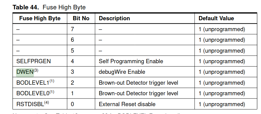
the default value of hfuse is '0xff', and set it to '0xf7' means debugwire enabled:
sudo avrdude -c usbasp -p t13 -U hfuse:w:0xf7:m
If you have AVR dragon and above programmer, you can unprogram 'DWEN':
sudo avrdude -c usbasp -p t13 -U hfuse:w:0xff:m
4.2.2 prepare the hardware
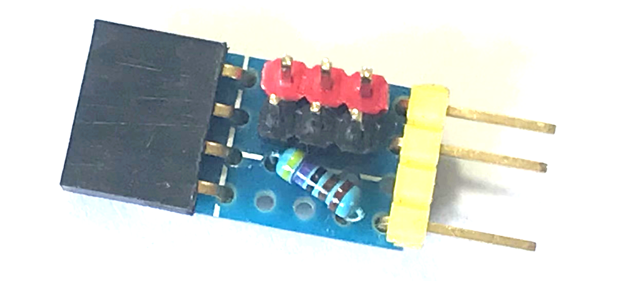
dwdebug uses an FT232R or CH340 USB serial adapter with RX connected directly to the DebugWIRE pin(the RESET pin now is debugwire pin), and TX connected through a 4.7k resistor to RX. you can also use a diode such as 1n914/1n4148/1n5819 or just a zener diode.
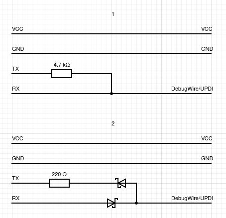
For convenient, I make a little board easy to fit my CH340 and FT2232 adapter:
4.2.3 program by dwdebug
sudo dwdebug l ./main.elf,qr
For more usage help of dwdebug, please refer to dwdebug manual.
With the self-made '4.7k serial adapter' (refer to above section), you can program UPDI with pyupdi.
Use Thinary nano 4808 and blink demo as example:
pyupdi -c /dev/ttyUSB0 -d atmega4808 -b 115200 -e -f main.hex
Use attiny816 as example to read the fuse bits:
pyupdi -c /dev/ttyUSB0 -d attiny816 -b 115200 -fr
The output looks like:
Device info: {'family': 'tinyAVR', 'nvm': 'P:0', 'ocd': 'D:0', 'osc': '3', 'device_id': '1E9321', 'device_rev': '0.1'}
Fuse:Value
0:0x00
1:0x00
2:0x02
3:0xFF
4:0x00
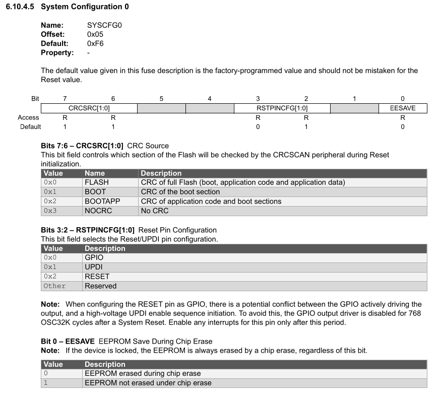
5:0xC4
6:0x04
7:0x00
8:0x02
9:0xFF
10:0xC5
Note the 5:0xC4, It means RSTPINCFG is set to 0x01, the UPDI pin works as UPDI.
You can program the FUSE value to 0xC8 (UPDI pin as RESET) or 0xC0 (UPDI pin as GPIO), but only HV UPDI programmer can unprogram it.
Program FUSE bit:
pyupdi -d attiny816 -b 115200 -c /dev/ttyUSB0 -fs "5:0xc8"
The output look like:
Device info: {'family': 'tinyAVR', 'nvm': 'P:0', 'ocd': 'D:0', 'osc': '3', 'device_id': '1E9321', 'device_rev': '0.1'}
Fuse 5 set to 0xC8 successfully
But after that, you can NOT use UPDI anymore since the pin works as GPIO, you have to use a HV UPDI programmer to unprogram it, such as with HV JTAG2UPDI programmer:
avrdude -C ./avrdude-jtag2updi.conf -c jtag2updi -p t816 -P /dev/ttyUSB0 -U fuse5:w:0xC4:m
For more information, pleaser refer to the datasheet of ATTINY816:
pymcuprog is a Python utility for programming various Microchip MCU devices using Microchip CMSIS-DAP based debuggers.
pymcuprog is primarily intended for use with PKOB nano (nEDBG) debuggers which are found on Curiosity Nano kits and other development boards. This means that it is continuously tested with a selection of AVR devices with UPDI interface as well as a selection of PIC devices. However since the protocol is compatible between all EDBG-based debuggers (pyedbglib) it is possible to use pymcuprog with a wide range of debuggers and devices, although not all device families/interfaces have been implemented.
pymcuprog supports:
- PKOB nano (nEDBG) - on-board debugger on Curiosity Nano
- MPLAB PICkit 4 In-Circuit Debugger (when in 'AVR mode')
- MPLAB Snap In-Circuit Debugger (when in 'AVR mode')
- Atmel-ICE
- Power Debugger
- EDBG - on-board debugger on Xplained Pro/Ultra
- mEDBG - on-board debugger on Xplained Mini/Nano
- JTAGICE3 (firmware version 3.0 or newer)
Install using pip from pypi:
pip install pymcuprog
Usage:
Test connectivity by reading the device ID:
pymcuprog ping
Erase memories then write contents of an Intel(R) hex file to flash using Curiosity Nano (pymcuprog does NOT automatically erase before writing):
pymcuprog erase
pymcuprog write -f app.hex
Erase memories and write an Intel hex file (using the --erase switch):
pymcuprog write -f app.hex --erase
Erase memories, write an Intel hex file and verify the content:
pymcuprog write -f app.hex --erase --verify
Pymcuprog also support self-made '4.7k serial adapter' (refer to above section),
For example: checks connectivity by reading the device identity:
pymcuprog ping -d atmega4808 -t uart -u /dev/ttyUSB0
Erase and write:
pymcuprog -t uart -d atmega4808 -u /dev/ttyUSB0 write -f main.hex --erase --verify
AVaRICE is a program which interfaces the GNU Debugger GDB with the AVR JTAG ICE available from Atmel. It can support a lot of official debugger devices, such as AVR JTAG ICE MKI/MKII/3, AVR Dragon and ATMEL-ICE etc.
Up to this tutorial written, most linux distribution shipped avarice-2.13 by default, version 2.13 can not support ATMEL-ICE, if you use ATMEL-ICE, you should use this version: https://github.com/Florin-Popescu/avarice/
Build and install it:
./configure --prefix=/usr/local --program-suffix=-2.14 --datadir=/usr/local/share/avarice-2.14
make
sudo make install
The program suffix and another datadir is to avoid conflict with avarice shipped by your distribution.
After installed, the command you can use is avarice-2.14.
Try run below command to find help information and determine the command args you should use according to your debugger hardware:
avarice-2.14 --help
Using atmega128 as example, after programming with avrdude, wire up the debugger and target board correctly (usually, there are two 10pin headers in your board, one for ISP and another one is JTAG), and open the terminal to luanch a avarice session,
For JTAG ICE, you may need to specify the port, here is '/dev/ttyUSB0':
avarice-2.14 -j /dev/ttyUSB0 :3333
And the output looks like
AVaRICE version 2.14dev

Defaulting JTAG bitrate to 250 kHz.

JTAG config starting.
Hardware Version: 0xc0
Software Version: 0x80
Reported JTAG device ID: 0x9702
Configured for device ID: 0x9702 atmega128
JTAG config complete.
Preparing the target device for On Chip Debugging.
Waiting for connection on port 3333.
For ATMEL-ICE, you should use:
avarice-2.14 -4 :3333
And the output looks like:
AVaRICE version 2.14dev

Defaulting JTAG bitrate to 250 kHz.

JTAG config starting.
Found a device, serial number: J42700018439
Reported device ID: 0x9702
Configured for device ID: 0x9702 atmega128
JTAG config complete.
Preparing the target device for On Chip Debugging.
Waiting for connection on port 3333.
And open another terminal to start avr-gdb as:
avr-gdb ./main.elf
Reading symbols from main.elf...
(gdb) target remote :3333
Remote debugging using :3333
0x00000000 in __vectors ()
(gdb) break main
Breakpoint 1 at 0xa4: file main.c, line 16.
(gdb) break 16
Note: breakpoint 1 also set at pc 0xa4.
Breakpoint 2 at 0xa4: file main.c, line 16.
(gdb) c
Continuing.
NOTE: the above command is for JTAG debugging protocol, apply '-w' arg for debugwire and '-u' for UPDI.
For AVR MCU supporting debugwire protocol, you can use dwdebug with self-made CH340/FTx232 adapter mentioned above for debugging. dwdebug itself is a debugger can be used standalone, and it can also work as a bridge to avr-gdb.
I prefer this way to debug some lowpin ATTINY models
Program the target device with:
dwdebug l ./main.elf,qr
Launch the dwdebug session with:
dwdebug device ttyUSB0
The output looks like:
Connected to ATtiny13 on /dev/ttyUSB0 at 9495 baud.
0036: 4030  sbci  r19, $0               >
After you get the '>' prompt, type 'help' for more info and launch gdb-server as:
0034: 5021  subi  r18, $1               > gdbserver
Target ready, waiting for GDB connection.

Info : avrchip: hardware has something
Use 'target remote :4444'
All REPL command of dwdebug can be used as commandline argument, to launch gdbserver, you can also do it as:
$ dwdebug gdbserver
Bloom implements a number of user-space device drivers, enabling support for many debug tools (such as the Atmel-ICE, Power Debugger, MPLAB SNAP, etc). Bloom exposes an interface to the connected target, via a GDB RSP server. This allows any IDE with GDB RSP client capabilities to interface with Bloom and gain full access to the target.
Currently, Bloom only supports AVR8 targets from Microchip. Bloom was designed to accommodate targets from different families and architectures. Support for other target families will be considered as and when requested.
You can download the prebuilt binary release from https://bloom.oscillate.io, it provides deb and rpm packages.
After installed, in your project dir, run:
bloom init
A 'bloom.json' will be generated, you need to modify this file to match your target, use thinary nano 4808 as example, 'bloom.json' should be:
{
  "environments": {
    "default": {
      "debugTool": {
        "name": "atmel-ice",
        "releasePostDebugSession": true
      },

      "target": {
        "name": "atmega4808",
        "physicalInterface": "updi"
      },

      "debugServer": {
        "name": "avr-gdb-rsp",
        "ipAddress": "127.0.0.1",
        "port": "1442"
      }
    }
  },

  "insight": {
    "enabled": true
  }
}
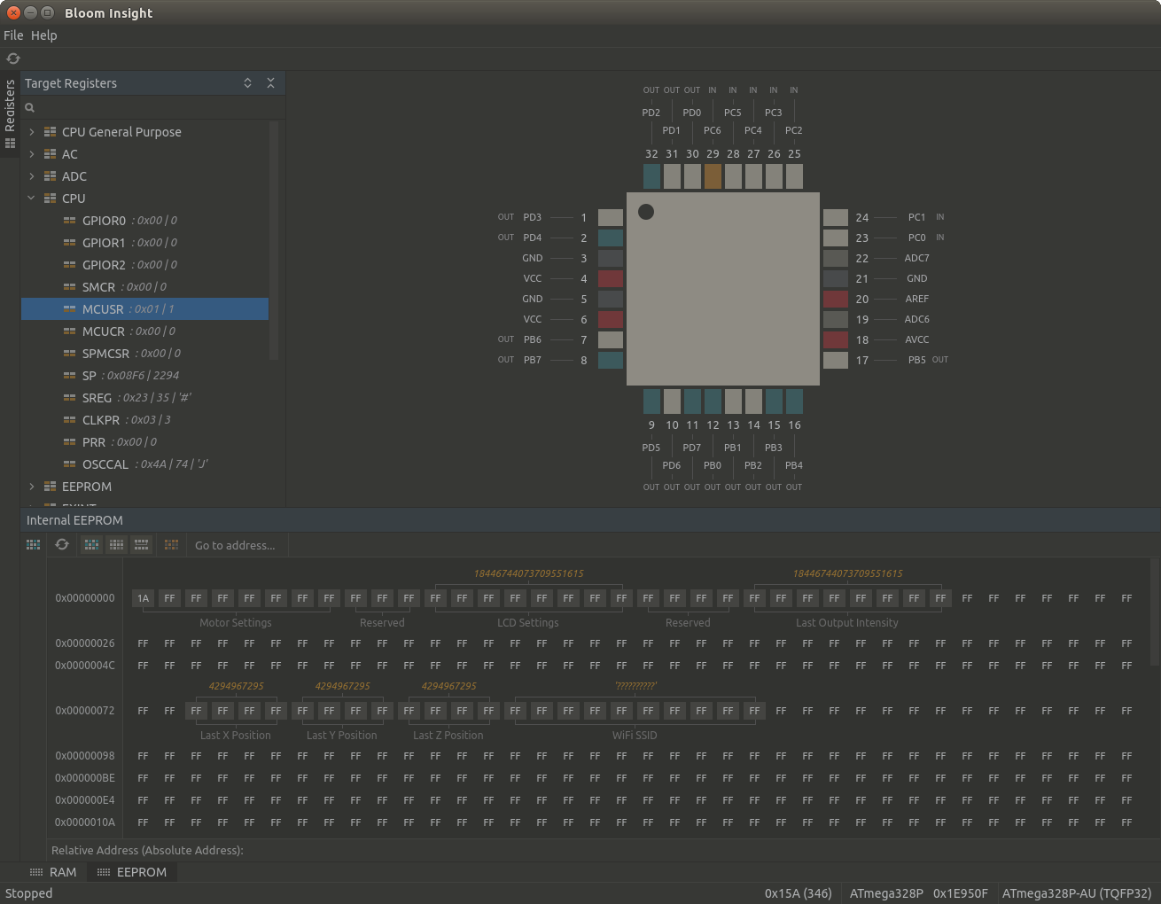
And then run bloom, the output looks like:
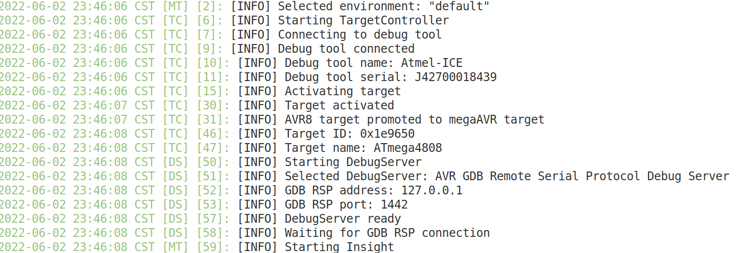
And the insight window also start but will not show useful information until avr-gdb connected.
Then you can launch a avr-gdb session with:
$ avr-gdb
(gdb) target remote :1442
NOTE : Some nano clone may be not work as expected,
According to https://www.electronics-lab.com/recover-bricked-attiny-using-arduino-as-high-voltage-programmer/, you can make a rescue board if you brick your attiny device. actually, it can be used to modify FUSE bit of attiny devices as you like.
The rescue board use arduino uno/nano as conroller and the circuit diagram here:
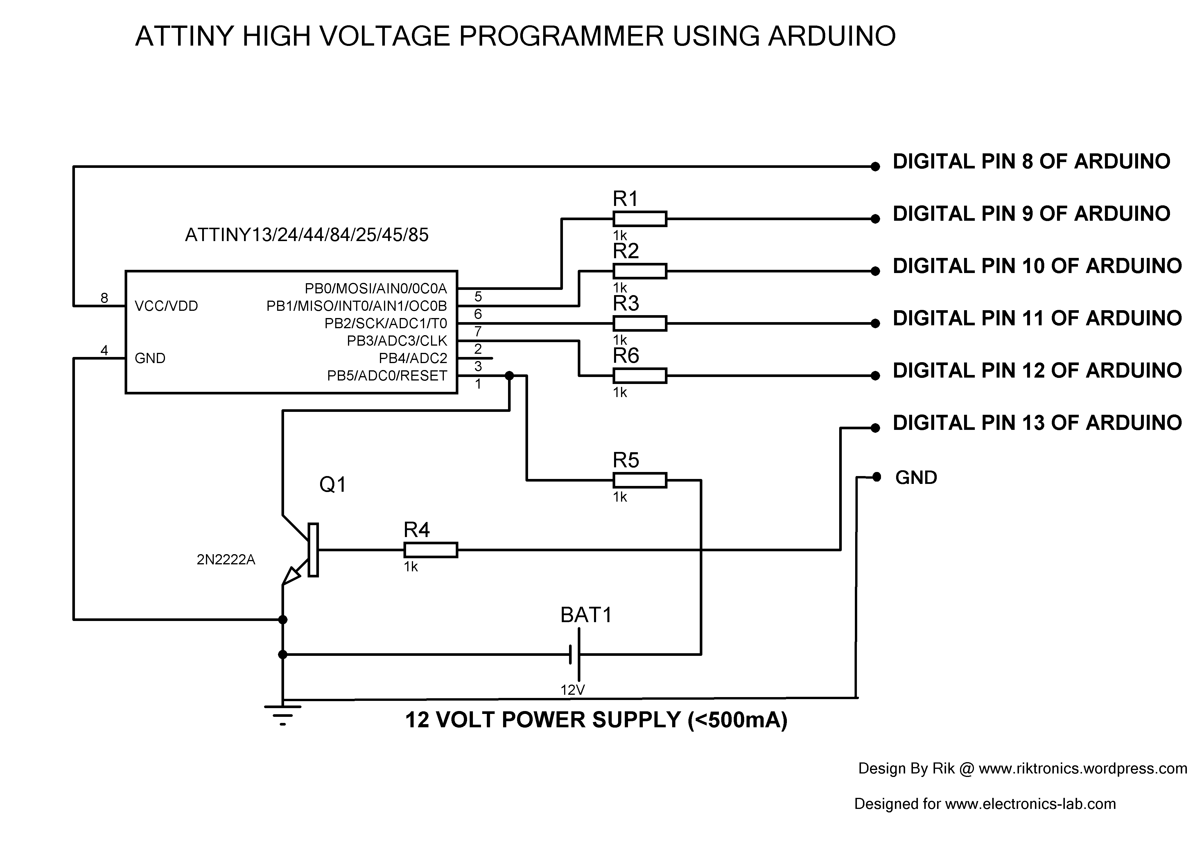
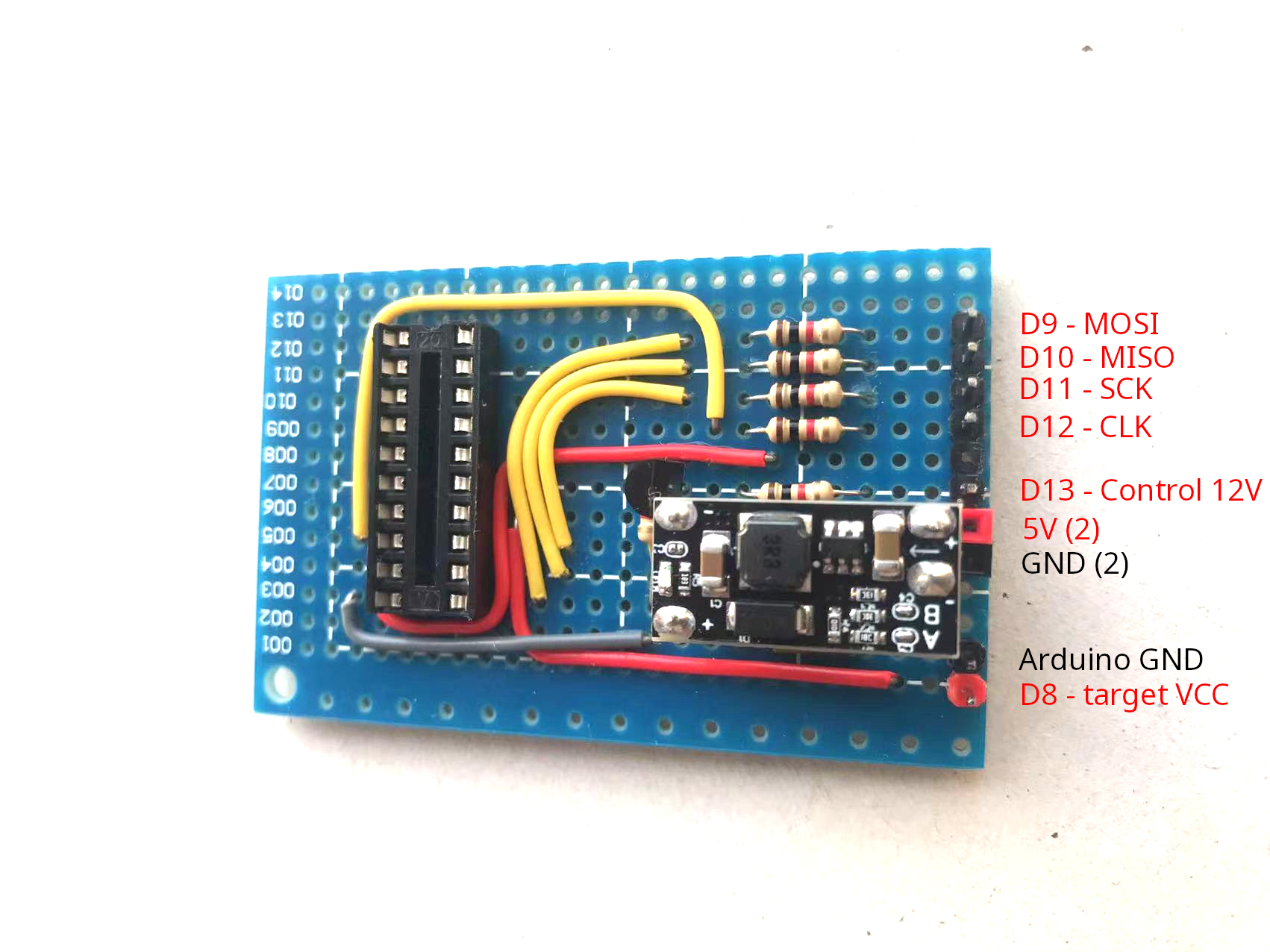
I suggest to make a board permanently and I make one with a 5v to 12v DC-DC converter,
'5V (2)' and 'GND (2)' are for seperated power supply to 5v to 12v convertor, the current of 12v output should less than 500ma, usually it's safe to use a 5V-1A charger.
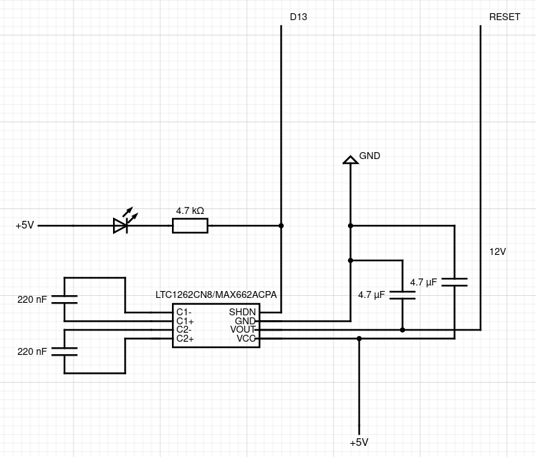
And the second version with LTC1262CN8 or MAX662A and Arduino nano dock:
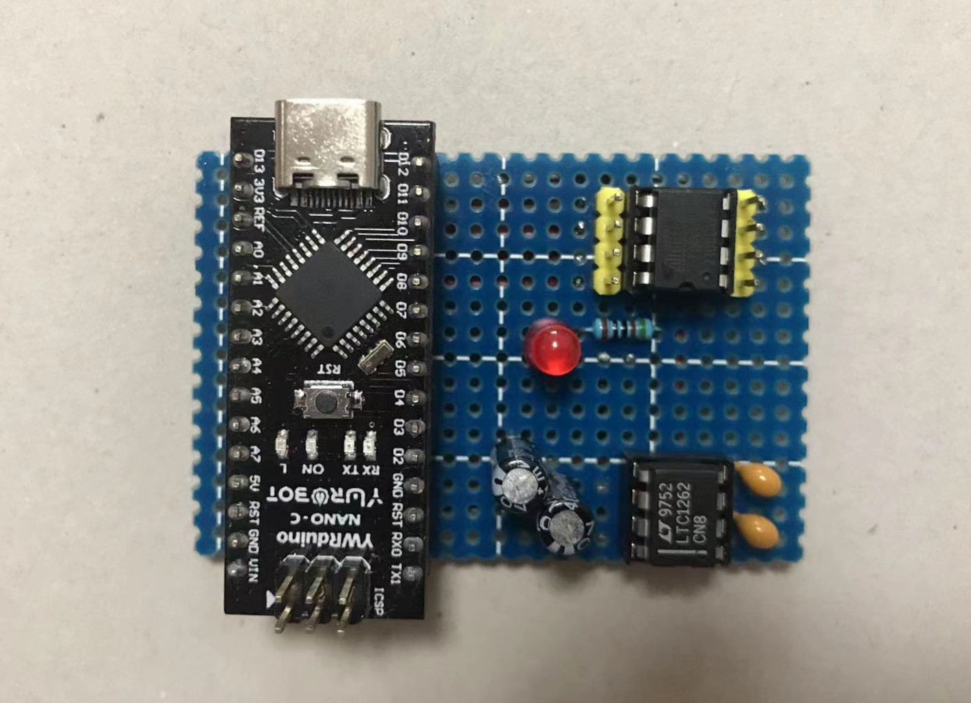
The difference compare to first version is using LTC1261CN8 or MAX662A to replace the 5v to 12v DC-DC converter:
Then upload below sketch to uno or nano with Arduino IDE, or use the dw-hv-reprogramer I provided in this repo:
// AVR High-voltage Serial Fuse Reprogrammer
// Adapted from code and design by Paul Willoughby 03/20/2010
// http://www.rickety.us/2010/03/arduino-avr-high-voltage-serial-programmer/
// Fuse Calc:
// http://www.engbedded.com/fusecalc/

#define RST 13 // Output to level shifter for !RESET from transistor
#define SCI 12 // Target Clock Input
#define SDO 11 // Target Data Output
#define SII 10 // Target Instruction Input
#define SDI 9 // Target Data Input
#define VCC 8 // Target VCC

#define HFUSE 0x747C
#define LFUSE 0x646C
#define EFUSE 0x666E

// Define ATTiny series signatures
#define ATTINY13 0x9007 // L: 0x6A, H: 0xFF 8 pin
#define ATTINY24 0x910B // L: 0x62, H: 0xDF, E: 0xFF 14 pin
#define ATTINY25 0x9108 // L: 0x62, H: 0xDF, E: 0xFF 8 pin
#define ATTINY44 0x9207 // L: 0x62, H: 0xDF, E: 0xFFF 14 pin
#define ATTINY45 0x9206 // L: 0x62, H: 0xDF, E: 0xFF 8 pin
#define ATTINY84 0x930C // L: 0x62, H: 0xDF, E: 0xFFF 14 pin
#define ATTINY85 0x930B // L: 0x62, H: 0xDF, E: 0xFF 8 pin

void setup() {
  pinMode(VCC, OUTPUT);
  pinMode(RST, OUTPUT);
  pinMode(SDI, OUTPUT);
  pinMode(SII, OUTPUT);
  pinMode(SCI, OUTPUT);
  pinMode(SDO, OUTPUT); // Configured as input when in programming mode
  digitalWrite(RST, HIGH); // Level shifter is inverting, this shuts off 12V
  Serial.begin(19200);
  Serial.println("Code is modified by Rik. Visit riktronics.wordpress.com and electronics-lab.com for more projects");
  Serial.println("-------------------------------------------------------------------------------------------------");
  Serial.println("Enter any character to start process..");
}


void loop() {
  if (Serial.available() > 0) {
    Serial.read();
    pinMode(SDO, OUTPUT); // Set SDO to output
    digitalWrite(SDI, LOW);
    digitalWrite(SII, LOW);
    digitalWrite(SDO, LOW);
    digitalWrite(RST, HIGH); // 12v Off
    digitalWrite(VCC, HIGH); // Vcc On
    delayMicroseconds(20);
    digitalWrite(RST, LOW); // 12v On
    delayMicroseconds(10);
    pinMode(SDO, INPUT); // Set SDO to input
    delayMicroseconds(300);
    unsigned int sig = readSignature();
    Serial.println("Reading signature from connected ATtiny......");
    Serial.println("Reading complete..");
    Serial.print("Signature is: ");
    Serial.println(sig, HEX);
    readFuses();
    if (sig == ATTINY13) {
      Serial.println("The ATtiny is detected as ATtiny13/ATtiny13A..");
      Serial.print("LFUSE: ");
      writeFuse(LFUSE, 0x6A);
      Serial.print("HFUSE: ");
      writeFuse(HFUSE, 0xFF);
      Serial.println("");
    } else if (sig == ATTINY24 || sig == ATTINY44 || sig == ATTINY84 ||
    sig == ATTINY25 || sig == ATTINY45 || sig == ATTINY85) {
      Serial.println("The ATtiny is detected as ");
      if(sig == ATTINY24) Serial.println("ATTINY24..");
      else if(sig == ATTINY44) Serial.println("ATTINY44..");
      else if(sig == ATTINY84) Serial.println("ATTINY84..");
      else if(sig == ATTINY25) Serial.println("ATTINY25..");
      else if(sig == ATTINY45) Serial.println("ATTINY45..");
      else if(sig == ATTINY85) Serial.println("ATTINY85..");

      writeFuse(LFUSE, 0x62);
      writeFuse(HFUSE, 0xDF);
      writeFuse(EFUSE, 0xFF);
    }

    Serial.println("Fuses will be read again to check if it's changed successfully..");
    readFuses();
    digitalWrite(SCI, LOW);
    digitalWrite(VCC, LOW); // Vcc Off
    digitalWrite(RST, HIGH); // 12v Off

    Serial.println("");
    Serial.println("");
    Serial.println("");
    Serial.println("");
  }
}

byte shiftOut (byte val1, byte val2) {
  int inBits = 0;

  //Wait until SDO goes high
  while (!digitalRead(SDO))
  ;

  unsigned int dout = (unsigned int) val1 << 2;
  unsigned int iout = (unsigned int) val2 << 2;

  for (int ii = 10; ii >= 0; ii--) {
    digitalWrite(SDI, !!(dout & (1 << ii)));
    digitalWrite(SII, !!(iout & (1 << ii)));
    inBits <<= 1; inBits |= digitalRead(SDO);
    digitalWrite(SCI, HIGH);
    digitalWrite(SCI, LOW);
  }
  return inBits >> 2;
}

void writeFuse (unsigned int fuse, byte val) {
  Serial.println("Writing correct fuse settings to ATtiny.......");

  shiftOut(0x40, 0x4C);
  shiftOut( val, 0x2C);
  shiftOut(0x00, (byte) (fuse >> 8));
  shiftOut(0x00, (byte) fuse);

  Serial.println("Writing complete..");
}

void readFuses () {
  Serial.println("Reading fuse settings from connected ATtiny.......");

  byte val;
  shiftOut(0x04, 0x4C); // LFuse
  shiftOut(0x00, 0x68);
  val = shiftOut(0x00, 0x6C);
  Serial.print("LFuse: ");
  Serial.print(val, HEX);
  shiftOut(0x04, 0x4C); // HFuse
  shiftOut(0x00, 0x7A);
  val = shiftOut(0x00, 0x7E);
  Serial.print(", HFuse: ");
  Serial.print(val, HEX);
  shiftOut(0x04, 0x4C); // EFuse
  shiftOut(0x00, 0x6A);
  val = shiftOut(0x00, 0x6E);
  Serial.print(", EFuse: ");
  Serial.println(val, HEX);
  Serial.println("Reading complete..");
}

unsigned int readSignature () {
  unsigned int sig = 0;
  byte val;
  for (int ii = 1; ii < 3; ii++) {
    shiftOut(0x08, 0x4C);
    shiftOut( ii, 0x0C);
    shiftOut(0x00, 0x68);
    val = shiftOut(0x00, 0x6C);
    sig = (sig << 8) + val;
  }
  return sig;
}
After upload the sketch, open 'serial monitor' of arduino IDE and set baudrate to 19200/no line ending, or use tio -b 19200 /dev/ttyUSB0, wire up as circuit diagram indicated.
When you get the msg:
Code is modified by Rik. Visit riktronics.wordpress.com and electronics-lab.com for more projects
-------------------------------------------------------------------------------------------------
Enter any character to start process..
Enter any character and the output will look like:
Reading signature from connected ATtiny......
Reading complete..
Signature is: 9007
Reading fuse settings from connected ATtiny.......
LFuse: 6A, HFuse: F7, EFuse: FF
Reading complete..
The ATtiny is detected as ATtiny13/ATtiny13A..
LFUSE: Writing correct fuse settings to ATtiny.......
Writing complete..
HFUSE: Writing correct fuse settings to ATtiny.......
Writing complete..

Fuses will be read again to check if it's changed successfully..
Reading fuse settings from connected ATtiny.......
LFuse: 6A, HFuse: FF, EFuse: FF
Reading complete..
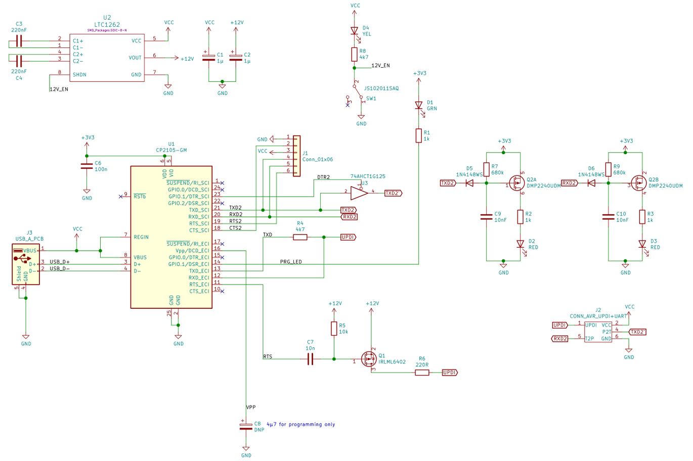
In this repo I provide a simple circuit that you can make a HV UPDI/Debugwire adapter by yourself, it can work with CH34x and other USB serial adapter (requires RTS pin). This adapter can work as debugwire, updi and HV UPDI programmer, and it does NOT need any code changes to pyupdi.

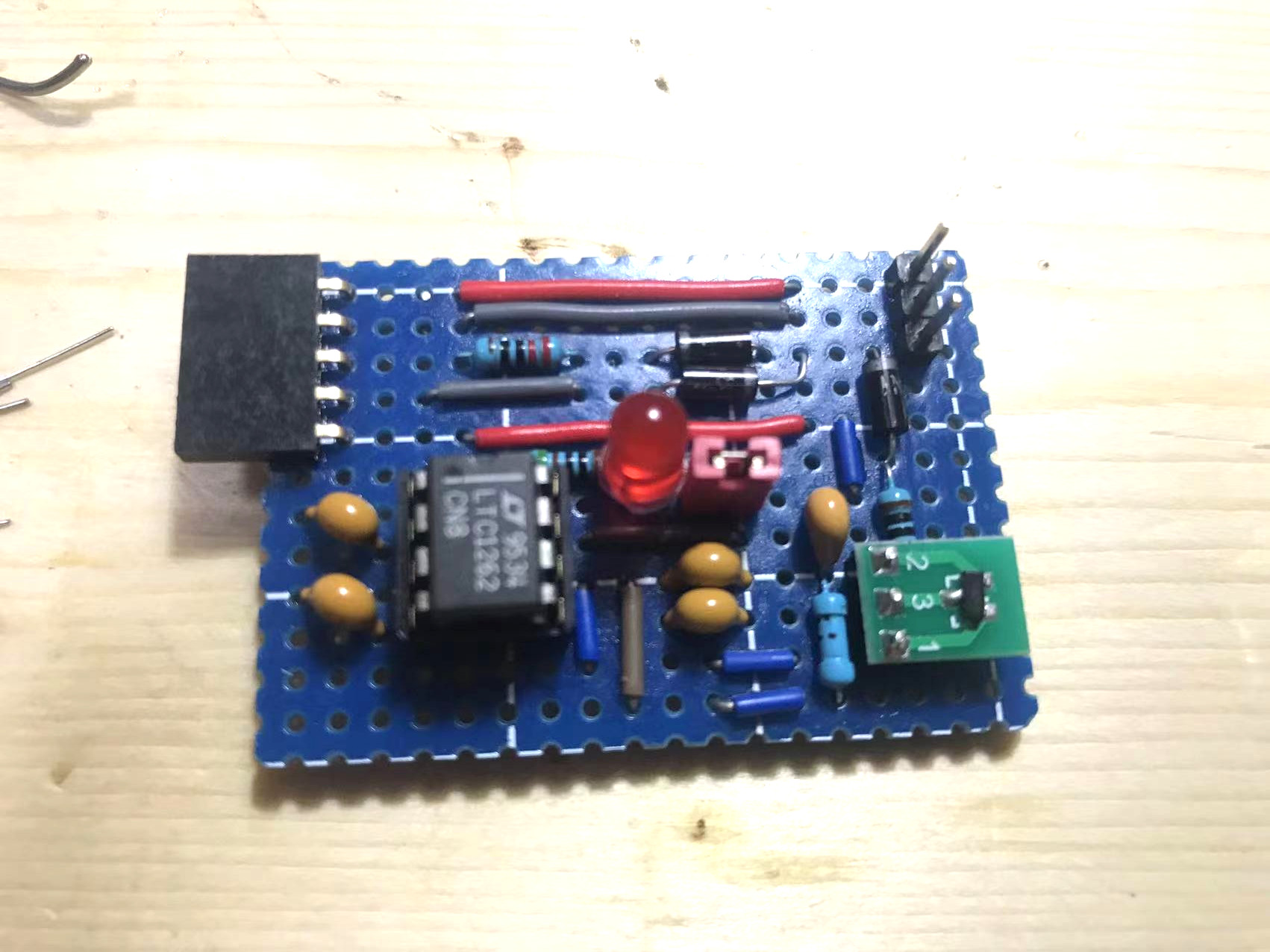
The BOM:
- one LTC1262CN8 DIP-8 or MAX662ACPA DIP-8, DC/DC converter.
- one SI2301CDS-T1-GE3 SOT-23 or IRLML6402TRPBF SOT-23, P-MOS
- one SOT-23 to 2.54 converter board
- two 220nF (224) capacitor
- two 1uF (105) capacitor
- one 10nF(103) or 100nF(104) or 1uF(105) capacitor
- two 220 Ohm resistor
- one 1k Ohm resistor
- three 1n914 or 1n4148 or 1n5819 schottky diode
For more information about High-Voltage UPDI, please refer to UPDI High-Voltage Activation Information.
I take below HV serial UPDI adapter as reference to design my HV Serial UPDI adapter, but note the original circuit design is not work with my CH341B USB serial adapter.
HV Serial UPDI:
https://www.tindie.com/products/leonerd/avr-updi-programmer-with-12v/
Another HV UPDI solution:
High voltage JTAG2UPDI (not recommended anymore):
https://github.com/Dlloydev/jtag2updi/wiki/Arduino-Nano-HV-UPDI-Programmer
https://github.com/Dlloydev/jtag2updi/wiki/DIY-AVR132DA-HV-UPDI-Programmer
https://github.com/Dlloydev/jtag2updi/wiki/DIY-ATmega4809-HV-UPDI-Programmer
https://github.com/Dlloydev/jtag2updi/wiki/DIY-ATtiny-HV-UPDI-Programmer
https://github.com/Dlloydev/jtag2updi/wiki/DIY-HV-UPDI-Programmer
If "avrdude : warning : Can not Set sck period . usbasp please check for firmware update", it means your usbasp adapter's firmware is outdated. it should still works well, it is NOT neccesary to update the firmware. but if you insist to do that, please follow this guide.