Ragel-based C-parser for Dutch Smart Meter P1-data
Author: Levien van Zon (levien at gnuritas.org)
DSMR (Dutch Smart Meter Requirements) is a standard for "smart" utility meters used in The Netherlands. Meters that comply with DSMR have several interfaces, including:
- P1, a send-only serial interface that can be used to connect local devices to an electricity meter. The connected devices can receive data from the electricity meter and its slave devices.
- P2, an M-bus interface used for communication between utility meters (e.g. a gas meter, a water meter and an electricity meter, whereby the electricity meter acts as a master and the other meters as slaves).
- P3, an infrastructure to periodically send aggregated meter data from an electricity meter to a central server, using a cellular modem (GPRS, CDMA or LTE), ethernet or power-line communication (PLC). Data is generally sent at most once per day, aggregated at 10-minute intervals, for a subset of variables.
- P4, which is strictly speaking not an interface at the meter level, but a standard for storing data on and retrieving data from a central server architecture.
In addition to the above interfaces, most DSMR-meters also have additional interfaces, such as an optical IEC 62056-21 serial interface and an S0 (DIN 43864) pulse-output (which is usually not accessible, unfortunately).
Several versions of the official DSMR P1 standard are included in the doc/ directory of this repository. Also included there are notes on the broader IEC 62056-21 standard, on which the P1-standard is based.
This repository contains a parser for DSMR data-telegrams, based on the Ragel state machine compiler, as well as the DSMR P1 specification documents (in doc/) and an example program in C for reading and parsing DSMR-data from a serial port in Linux (on any other POSIX system such as BSD or MacOS). To compile the Ragel parser and the example program, you need to install the Ragel state machine compiler (on Debian, Ubuntu and derivatives, simply do: sudo apt-get install ragel, on other systems you can git clone git://colm.net/ragel.git) and run ./make.sh. In principle this parser can also be adapted for use on microcontrollers, although I haven't tried this yet.
In addition to DSMR P1-telegrams, the parser can handle more general IEC 62056-21 telegram data, albeit with a very limited set of OBIS-objects, so that it can be used to obtain energy readings from many non-DSMR smart meters through the optical port. The parser has been tested with example data from all currently known versions of DSMR (2.2, 3.0, 4.x and 5.0.2), and with real data from a Landis-Gyr and Kaifa DSMR 4.2 electricity meters, in some cases with a slave gas meter connected. This code is open-source under the Apache 2.0 licence.
The DSMR P1-port uses an RJ12 (6P6C) modular connector, which has 6 pins:
- Vcc: +5V power supply, max. 250 mA continuous (DSMR >= 4.0)
- RTS: data request, connect to +5V (4.0 - 5.5 V) to request data, connect to 0V/GND to stop data transmission
- GND: data ground
- NC: not connected
- TXD: data line (open collector output, logically inverted 5V serial signal, 8N1, 115200 baud for DSMR >= 4.0, 9600 baud for DSMR < 4.0)
- VccGND: power ground (DSMR >= 4.0)
All P1-pins are galvanically isolated from mains through an opto-coupler, and have over-voltage protection. The data-line is an open-collector serial line output, which means that the signal is inverted relative to a normal serial line, and that it requires a pull-up resistor (1 - 10 kOhm) to be connected between RXD (pin 5) and the serial voltage required (for +5V you can connect it to Vcc / pin 1 or RTS / pin 2 on the P1-port).
If RTS is set to HIGH, an ASCII text-based data-packet called a "telegram" is sent by the smart meter, either every 10 seconds (DSMR < 5.0) or every second (DSMR >= 5.0). The format of the telegrams is derived from the IEC 62056-61 standard for exchanging data with utility meters.
There are roughly three ways to connect the P1-port to a computing device:
- Directly to a 5V or 3.3V TTL serial interface (e.g. the one on a Raspberry Pi), using a transistor (e.g. BC547) and some resistors (e.g. 1 kOhm and/or 10 kOhm) to invert the signal and to pull it up to the required voltage. There is a possible schematic here.
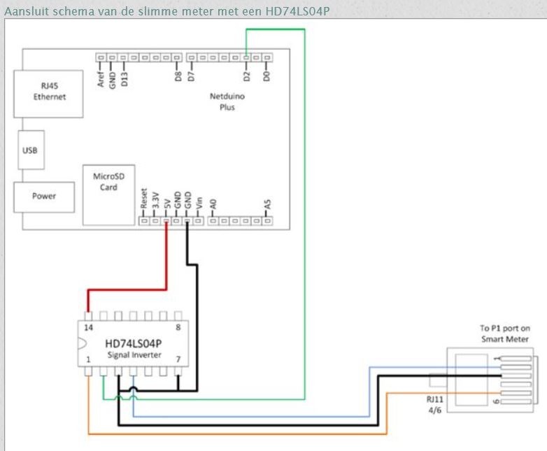
- Directly to a TTL serial interface using an inverter IC (e.g. a SN7404) to invert the signal, as shown in this example.
- Using an RS232-port (or a USB-RS232-converter) and a pull-up resistor. This is often the easiest solution, as this can be done without soldering, cheap USB RS232-converters are easy to find and you can add as many interfaces as you need (e.g. using multiple USB-devices or even a 4-port device based on an MCS7840 quad serial controller). The RS232 serial standard and the P1 standard both use an inverted serial signal, and altough the LOW voltage levels are technically incompatible (-15V to -3V for RS232, 0V to 1V for P1), most RS232-interfaces accept 0V as LOW and are able to decode the data transmitted by the P1-port without any problems. Just connect the signal ground of the two interfaces, and connect TXD on the P1-port to RXD on the RS232-interface. You will also still need to connect a 1-10 kOhm pull-up resistor between Vcc and the data line, and connect RTS on the P1-port to Vcc. You may also have to connect VccGND and GND.
You can also get a prefabricated P1 to USB cable (easily ordered online, e.g. from SOS Solutions, slimmemeterkabel.nl, Sinforcon or Oloey). So far, every USB RS232-converter I tested worked, and most Linux-kernels support the more common converter chips out-of-the-box, and will make the data available on the /dev/ttyUSB0 serial device.
If you build your own cable, it's easiest to connect pins 1 and 2 of the P1-interface together, and to connect a 1-10 kOhm pull-up resistor between either of these and pin 5 (TXD). Then simply connect RXD of your serial interface to TXD on the P1-port, and connect the data ground on both interfaces. You may also have to connect pin 6 (VccGND) to the data ground (pin 3) for the cable to work on some meters. Cables can be made without soldering, e.g. by using Wago 221-412 splicing connectors. I've used a 4-port USB-interface with these DB9 female terminal block connectors to read up to four meters at once. I made the cables using three-pair UTP-cable and RJ12-connectors, with a 1 kOhm pull-up resistor and several splicing connectors neatly packed away in a small junction box.
By default, the software echoes P1-telegrams back to the serial interface, so you can connect other devices that also read P1-data. If you're using RS232, you will need to convert the ca. 15V signal on the TXD-pin to 5V (e.g. using a L7805 linear converter), before handing it on to another device. If you're using a TTL serial interface, you will need to invert the TXD signal using a transistor or inverter IC. Especially if you're using a 3.3V serial interface, it's probably easiest to use an inverter IC with an open collector output, such as the SN7406, or an NPN-transistor to invert the signal and create an open collector output.
If you're connecting the P1-interface directly to the serial pins on a Raspberry Pi using a transistor, you may need to configure your Raspberry Pi Linux system to leave the serial port alone. This involves removing the references to the serial device (/dev/ttyAMA0) in /boot/cmdline.txt (disable the kernel debugging output to serial) and /etc/inittab (disable the serial command shell), instructions on how to do this can be found in this guide.
To test if data is coming in and the signal is inverted correctly, just compile and run the test program, and check if it sees any valid telegrams.
On Raspbian and some other systems, you may have to install a C-compiler to compile the parser and the test program, e.g. sudo apt-get install build-essential. You may also have to install Ragel: sudo apt-get install ragel. Then clone the git-repository, compile the test program and run it:
git clone https://github.com/lvzon/dsmr-p1-parser.git
cd dsmr-p1-parser
./make.sh
./p1-test-p1 /dev/ttyUSB0 errors.dat
If valid telegrams are coming in, you should see something like this within about 10 seconds:
Input device seems to be a serial terminal
Possible telegram found at offset 0
Possible telegram end at offset 624
New-style telegram with length 630
Header: XMX5LGBBFG1012463538
P1 version: 4.2
Timestamp: 1527686221
Equipment ID: E0031003262xxxxxx
Energy in, tariff 1: 1234.000000 kWh
Energy in, tariff 2: 1235.000000 kWh
Energy out, tariff 1: 0.000000 kWh
Energy out, tariff 2: 0.000000 kWh
Tariff: 2
Power in: 0.048000 kW
Power out: 0.000000 kW
Power failures: 2
Long power failures: 1
Power failure events: 1
Power failure event at 1484629982, 6885 s
Voltage sags L1: 0
Voltage swells L1: 0
Current L1: 0 A
Power in L1: 0.048000 kW
Power out L1: 0.000000 kW
Device 1 type: 3
Device 1 ID: G0025003407xxxxxx
Device 1 counter at 1527685200: 123.000000 m3
CRC: 0x9b8d
Parsing successful, data CRC 0x9b8d, telegram CRC 0x9b8d
If you get an error, check if the serial converter is connected and you're using the the correct serial device (depending on your setup it can also be /dev/ttyAMA0, /dev/ttyS0, /dev/ttyUSB1 or something else, check dmesg to be sure). If no valid telegram is seen within 25 seconds or so, hit CTRL-C and check errors.dat. The program tries to autodetect the baud rate, so if errors.dat contains garbage, you probably forgot to invert the signal, or you're inverting it twice. If errors.dat is empty, try dumping the serial device data directly (e.g. cat /dev/ttyUSB1). If no data comes in, check your cable connections and especially check if your data-line and ground and pull-up resistor are all connected correctly and the request-pin 2 is connected to at least +4V (and at most 5.5V).
If the cable-length is more than a few metres, this can cause the voltages to drop below 4 V, so you may need to measure this and either use a better cable or connect the pull-up resistor and Vcc-RTS at the P1-side rather than at the serial interface. Also note that older (DSMR 2.x or 3.x) metres do not have a 5V Vcc pin, so in this case you'll need to supply 5V or 3.3V from another source.
The packmsg-branch contains an experimental application that reads telegrams from a serial device and echoes the telegrams back to the interface. Telegram data is parsed, and energy, power and gas data is sent directly to a server socket, using a very compact encoding based on MessagePack. This application is functional but still under development, I use it in a pilot project to collect and act upon smart meter data in real time. I will try to include an example server and more documentation soon.
- Include packmsg-server example (Python code).
- Document p1-lib data structure and functions.
- Test with more meters.
- Adapt the parser for use on non-POSIX microcontroller platforms.
I wrote this parser for use at LENS, because I needed something that was light-weight and complete, and there currently does not seem to be another full DSMR P1 telegram-parser that is open-source and can be used in regular C programs. However, there are many parsers in many other programming languages:
- Matthijs Kooijman's DSMR P1-parser for Arduino, written in C++.
- Go library for reading/parsing P1-data
- DSMR P1-parser in C#
- DSMR 4.2 P1 data collector in NodeJS
- A very basic DSMR 4 P1-parser in JavaScript
- DSMR P1 parser in Python.
- Python module to read/parse P1-data
- Another very basic DSMR P1-reader/parser in Python
- Dennis Siemensma's extensive DSMR reader software and GUI in Python
- Arne Kaas' P1 data logger, using Python and SQLite
- Another Python P1 data logger
- And yet another P1 data logger using Python and MySQL
- A DSMR 4.2 P1-reader using PHP and MySQL
For more information on interfacing with the P1-port (mostly in Dutch):
- http://domoticx.com/p1-poort-slimme-meter-uitlezen-hardware/
- http://domoticx.com/p1-poort-slimme-meter-hardware/
- http://domoticx.com/arduino-p1-poort-telegrammen-uitlezen/
- https://jeelabs.org/article/1621a/
- https://thinkpad.tweakblogs.net/blog/10673/uitlezen-van-de-slimme-meter-p1-poort-met-een-arduino-en-waarden-opslaan-in-mysql-database