Continuity Checks
The interface PC boards sold by Clough42 come with connectors that must be soldered by the end user. If you are having trouble getting yours to work, start by checking for missed, cracked, or otherwise suspect solder joints. Use magnification if available.
If all of the joints look good, use a multimeter to check that you have good continuity. Most multimeters have a continuity mode in which it beeps when the probes are touched together. You can use this mode with the diagrams below to verify the the pins are actually making good connection to the circuits on the board.
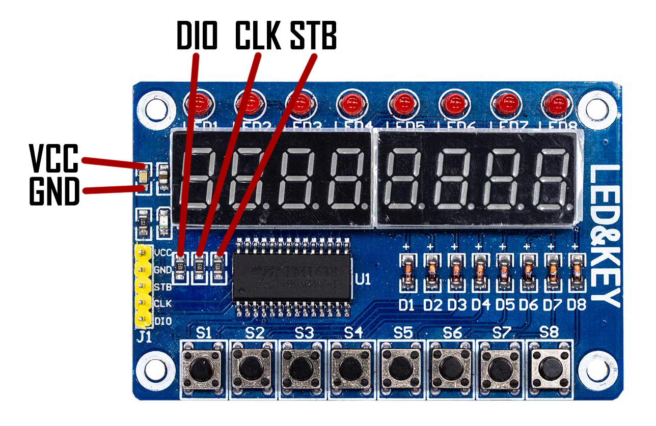
The control panel PCB has a five-pin connector that must be removed and replaced on the back side of the board. You can check to be sure the new connector is making good contact by probing between each connector pin and the indicated locations on the PCB. Try to touch only the tip of the pin to be sure you're testing the pin for contact and not the solder joint.
For example, the meter should beep if you probe the pin labeled VCC on the PCB silkscreen and the solder joint on the component indicated VCC in the picture.
The ELS Boost interface board has many connections on it, so I have broken up the connections into several groups. In each of the below images, the lines indicate where there should be continuity. If you probe the indicated locations and don't get a beep from your meter, you may have a bad solder joint.
For the servo connector, it's best to plug in the mating screw terminal and probe the screw to test for continuity.
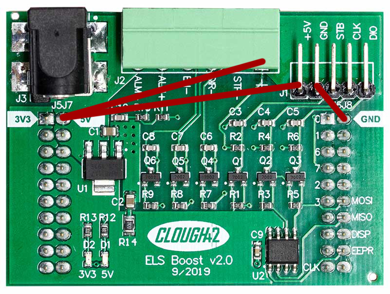
The first thing to check is the power connections. +5V power should be connected to both the stepper/servo connector and the control panel connector.
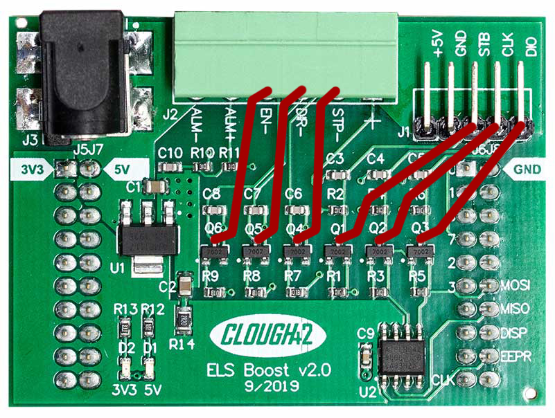
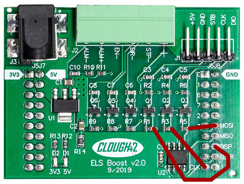
The output pin connections are shown below. You should have continuity from the top pin of each transistor to the corresponding output pin as shown. You can probe the pins directly. For the servo connector, you can insert the screw terminals and probe on the screw heads.
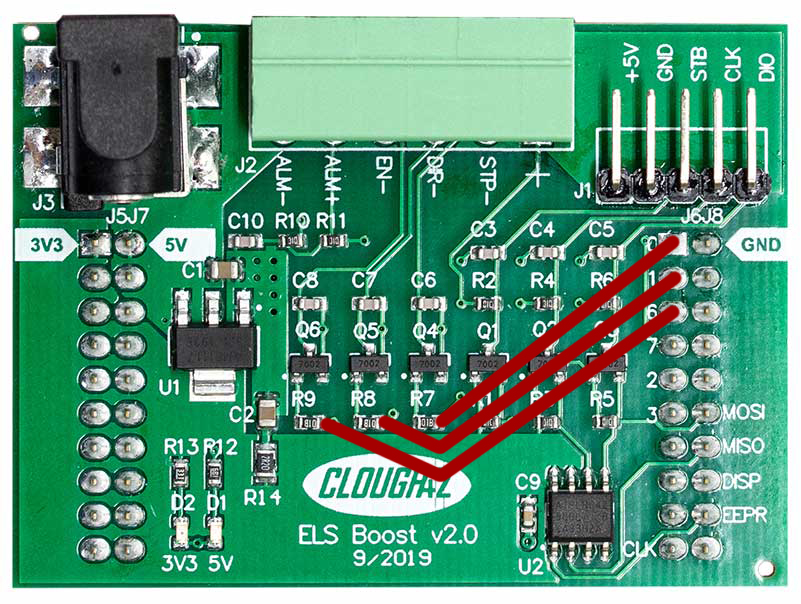
The connections for all of the input pins are shown below. For the pins that connect to the LaunchPad, try to probe directly on the tip of the pin to make sure you're testing that the pin is connected, and not just the solder at the base of the connection.
If all of the above connections test good, the next step is to test your cables. The best way to be sure your cables are making good connection is to connect all of the PC boards together and test end-to-end. Use the diagrams above and the silkscreened labels on the board to check that you have connectivity from board-to-board.
For example: you previously checked that the top pin on transistor Q3 is connected to the DIO pin. With the ELS board connected to the control panel board, test that the same pin of Q3 has continuity all the way to the pad labeled DIO on the control panel board, as indicated in the image above.
If all of the connections test good, your cabling and solder joints are probably not your issue.